


 Loading...
Installation, Operation
& Maintenance Manual
Installation, Betrieb und Wartungshandbuch Manual de Instalación, Operación y Mantenimento
ST100 Series
Thermal Mass Flow Meter
Fluid Components International LLC (FCI). All rights reserved.

ST100 Series Flow Meter
Notice of Proprietary Rights
This document contains confidential technical data, including trade secrets and proprietary information which is the property of Fluid Components International LLC (FCI). Disclosure of this data to you is expressly conditioned upon your assent that its use is limited to use within your company only (and does not include manufacture or processing uses). Any other use is strictly prohibited without the prior written consent of FCI.
© Copyright 2011 by Fluid Components International LLC. All rights reserved. FCI is a registered trademark of Fluid Components International LLC. Information subject to change without notice.
Fluid Components International LLC

ST100 Series Flow Meter |
06EN003400 Rev. D |
Table of Contents |
|
1 GENERAL..................................................................................................................................................................................................... |
1 |
Product Description........................................................................................................................................................................................................... |
1 |
Theory of Operation.......................................................................................................................................................................................................... |
1 |
Safety Instructions............................................................................................................................................................................................................ |
1 |
Order Verification.............................................................................................................................................................................................................. |
1 |
Hardware - Model Descriptions.................................................................................................................................................................................... |
1 |
Documentation and Accessories................................................................................................................................................................................... |
2 |
Supplemental Manuals , optional................................................................................................................................................................................. |
2 |
Supplemental Software, optional.................................................................................................................................................................................. |
2 |
Technical Specification..................................................................................................................................................................................................... |
3 |
2 INSTRUMENT INSTALLATION................................................................................................................................................................. |
5 |
Instrument Identification and Outline Dimensions........................................................................................................................................................... |
5 |
Insertion Sensor Installation............................................................................................................................................................................................. |
5 |
Flange Mount.................................................................................................................................................................................................................... |
7 |
NPT Pipe Thread Mount ................................................................................................................................................................................................... |
7 |
Adjustable/Retraceable Packing Gland Mounting........................................................................................................................................................... |
8 |
STP100 and STP102A Flow Element Installation............................................................................................................................................................. |
8 |
Flow Element Wiring..................................................................................................................................................................................................... |
8 |
STP100/102A Electronics Description........................................................................................................................................................................... |
8 |
Troubleshooting............................................................................................................................................................................................................. |
9 |
ST102A and STP102A Flow Element Installation............................................................................................................................................................. |
9 |
Installed Point Locations ............................................................................................................................................................................................... |
9 |
Flow Element Wiring................................................................................................................................................................................................... |
10 |
ST/STP102A Electronics Description........................................................................................................................................................................... |
10 |
Troubleshooting........................................................................................................................................................................................................... |
11 |
In-Line Sensor Installation.............................................................................................................................................................................................. |
11 |
Flow Transmitter Electronics Installation....................................................................................................................................................................... |
11 |
Integral Electronics......................................................................................................................................................................................................... |
11 |
Remote Electronics......................................................................................................................................................................................................... |
12 |
Remote Pipe Mounting................................................................................................................................................................................................... |
13 |
Instrument Wiring........................................................................................................................................................................................................... |
13 |
Post Installation Check.................................................................................................................................................................................................... |
15 |
Basic Commissioning and Start-Up................................................................................................................................................................................ |
15 |
HMI Display Navigation.................................................................................................................................................................................................. |
17 |
System Fault and Alarm Indication ............................................................................................................................................................................. |
18 |
Functions......................................................................................................................................................................................................................... |
18 |
Real Time Clock Setup................................................................................................................................................................................................. |
18 |
Totalizer........................................................................................................................................................................................................................ |
20 |
Data Logging................................................................................................................................................................................................................ |
22 |
Manual Start Logging Method.................................................................................................................................................................................... |
23 |
Log File Contents......................................................................................................................................................................................................... |
24 |
Fluid Components International LLC |
i |

06EN003400 Rev. D |
ST100 Series Flow Meter |
APPENDIX A - OUTLINE DIMENSIONAL DRAWINGS......................................................................................................................... |
27 |
APPENDIX B - WIRING DIAGRAMS........................................................................................................................................................ |
37 |
Figure B-1: Integral - AC Input Power, Analog and HART Output............................................................................................................................... |
38 |
Figure B-2: Remote - AC Input Power, Analog and HART Output.............................................................................................................................. |
38 |
Figure B-3: Integral - DC Input Power, Analog and HART Output............................................................................................................................. |
39 |
Figure B-4: Remote - DC Input Power, Analog and HART Output............................................................................................................................. |
39 |
Figure B-5: Integral - AC Input Power, Foundation fieldbus Output.............................................................................................................................. |
40 |
Figure B-6: Remote - AC Input Power, Foundation fieldbus Output.............................................................................................................................. |
40 |
Figure B-7: Integral - DC Input Power, Foundation fieldbus Output............................................................................................................................. |
41 |
Figure B-8: Remote - DC Input Power, Foundation fieldbus Output............................................................................................................................. |
41 |
Figure B-9: Integral - AC Input Power, Modbus Output.............................................................................................................................................. |
42 |
Figure B-10: Remote - AC Input Power, Modbus Output............................................................................................................................................. |
42 |
Figure B-11: Integral - DC Input Power, Modbus Output............................................................................................................................................ |
43 |
Figure B-12: Remote - DC Input Power, Modbus Output............................................................................................................................................ |
43 |
Figure B-13: Remote - 8 Conductor Interconnection Cable........................................................................................................................................ |
44 |
Figure B-14: Source - Pulse/Fequency Output............................................................................................................................................................. |
44 |
Figure B-15: Sink - Pulse/Fequency Output................................................................................................................................................................ |
45 |
Figure B-16: Flow Element Connection - Integral/Remote......................................................................................................................................... |
45 |
Figure B-17: Flow Element Connection - Remote....................................................................................................................................................... |
46 |
Figure B-18: Remote - 10 Conductor Interconnection Cable...................................................................................................................................... |
46 |
APPENDIX C APPROVALS......................................................................................................................................................................... |
47 |
APPENDIX D CUSTOMER SERVICE......................................................................................................................................................... |
53 |
Customer Service/ Technical Support......................................................................................................................................................................... |
53 |
Warranty Repairs or Returns....................................................................................................................................................................................... |
53 |
Non-Warranty Repairs or Returns............................................................................................................................................................................... |
53 |
Extended Warranty...................................................................................................................................................................................................... |
54 |
Return to Stock Equipment.......................................................................................................................................................................................... |
54 |
Field Service Procedures.............................................................................................................................................................................................. |
54 |
Field Service Rates...................................................................................................................................................................................................... |
54 |
Return Authorization Request.................................................................................................................................................................................... |
55 |
ii |
Fluid Components International LLC |

ST100 Series Flow Meter |
GENERAL |
1 GENERAL
Product Description
The ST100 Series is a thermal dispersion, industrial process grade air/gas flow meter. It is suitable for all air and gas flow measurement applications in line sizes from 1” to 100” [25 to 2500 mm] and larger. The instrument provides direct mass flow measuring and measures flow rate, totalized flow and temperature, and the STP versions add pressure measurement.
The measurements are made available to the user by way of 4-20mA analog output channels with HART or pre-selected digital bus protocols. The optional graphics display provides real-time process variable values along with flow range and process description information.
There are no moving parts to clean or maintain. It is offered in a wide selection of process connections to fit with any process piping and versions are available for temperature service from -40°F [-40°C] to 850°F [454°C].
ST100’s electronics/transmitter can be integrally mounted with the flow sensor or remote mounted up to 1000’ [300m] from the sensor element. Additional patented and/or FCI exclusive features include VeriCal® in-situ calibration verification, SpectraCalTM user selectable gas mixes, Dual sensor/single transmitter models and a built-in data logger capable of storing more than 20M readings. All ST100’s are precision calibrated in FCI’s world-class, NIST traceable calibration facility on one of our flow stands matched to your gas application and actual installation conditions.
Theory of Operation
The instrument functionally is based on the thermal dispersion operating principal. A low powered heater produces a temperature differential between two resistance temperature detectors (RTDs) by heating one of the RTDs above process temperature. As the process mass flow rate changes, the differential temperature between the RTDs changes. The differential temperature between the RTDs is proportional to the process mass flow. The flow transmitter converts the RTD differential temperature signal into a scaled flow output signal. The signal from the unheated RTD is used to provide the process temperature value.
Safety Instructions
•Warning – Explosion Hazard. Do not disconnect equipment when flammable or combustible atmosphere is present.
•Field wiring shall be in accordance with NEC (ANSI-NFPA 70) for Division 2 hazardous locations CEC (CSA C22.1) for division 2 locations as applicable.
•The instrument must be installed, commissioned and maintained by qualified personnel trained in process automation and control instrumentation. The installation personnel must ensure the instrument has been wired correctly according to the applicable wiring diagram.
•All location specific installation and wiring requirements must be met and maintained. FCI recommends an input power circuit breaker be installed between the power source and the flow meter. This facilitates easy power disconnection during commissioning and maintenance procedures. A switch or circuit breaker is required if installation is in a hazardous area.
•The flow meter contains electrostatic discharge (ESD) sensitive devices. Use standard ESD precautions when handling the circuit board assemblies.
•Hazardous Areas: The instrument is designed for use in hazardous areas. The approved area classification is identified on the nameplate along with the temperature and pressure limitations. The USB port and the Serial Communication port do not support the hazardous area requirements and should only be used when the area is declassified.
•When mounting the flow element into the process pipe, it is important that a lubricant/sealant is applied to the mating threads. A lubricant/ sealant compatible with the process conditions should be used. All connections should be tightened firmly. To avoid leaks do not overtighten or crossthread connections.
Order Verification
•Verify the received hardware matches the purchased hardware and application requirements. Verify the Model number part number on the instrument I.D. tag (i.e. ST100 – 10C0…) matches the purchased Model number part number.
•Review the Calibration requirements as specified on the Engineering Data Sheet in the documentation package. Verify the flow, temperature and pressure limits meet the application requirements.
Hardware - Model Descriptions
ST100 – Single point insertion element with flow and temperature process output
ST100L – In Line element with flow and temperature process output
ST102 – Dual point insertion elements with flow and temperature process output
Fluid Components International LLC |
1 |
GENERAL |
ST100 Series Flow Meter |
ST110 – Single point insertion element with flow and temperature process output, VeriCal option
ST112 – Dual point insertion elements with flow and temperature process output, VeriCal option
STP100 – Single point insertion element with flow, temperature and pressure process output
STP102 – Dual point insertion elements with flow, temperature and pressure process output
STP110 – Single point insertion element with flow and temperature process output, VeriCal option
STP112 – Dual point insertion elements with flow and temperature process output, VeriCal option
Documentation and Accessories
06EN003400 |
Installation and Operation Manual |
06EN003403 |
ST100 Configuration Software Manual |
Calibration Certification Documentation |
|
PC Configuration Software and USB Cable |
|
Supplemental Manuals , optional |
|
06EN003404 |
HART Operation Manual |
06EN003405 |
Foundation™ fieldbus Manual |
06EN003406 |
Modbus Operation Manual |
06EN003407 |
PROFIBUS Operation Manual |
06EN003408 |
VeriCal In-Situ Calibration Verification Operation Manual |
Supplemental Software, optional
HART DD Files
Foundation fieldbus
PROFIBUS DD File
PDM/DTMs
2 |
Fluid Components International LLC |

ST100 Series Flow Meter GENERAL
Technical Specification
Instrument |
|
within calibrated flow range; up to 1000:1 possible with factory |
|
Measuring Capability |
evaluation of application |
||
ST1XX Models: Flow rate, total flow and temperature |
Temperature Compensation |
||
STP1XX Models: Flow rate, total flow, temperature and pressure |
Standard: ± 30 °F [± 16 °C] |
||
Basic Style |
|
Optional: ± 100 °F [± 55 °C] |
|
|
Agency Approvals pending |
||
ST100: |
Insertion, single-point |
||
ST100L: |
In-line (spool piece), single-point |
FM, FMc: Class I, Division 1, Hazardous Locations; |
|
ST102: |
Insertion, dual-element system |
Groups B,C,D,E,F,G |
|
ST110: |
Insertion, single-point with VeriCal™ capability |
ATEX and IECEx: Zone 1, II 2 GD Ex d IIC T4 |
|
ST112: |
Insertion, dual-element system with VeriCal capability |
CPA, NEPSI |
|
STP100: |
Insertion, single-point with pressure measurement |
Calibration |
|
STP102: |
Insertion, dual-element system with pressure measure- |
Performed on NIST traceable flow stands and equipment |
|
STP110: |
ment |
Flow Element |
|
Insertion, single-point with pressure measurement and |
|||
Material of Construction |
|||
STP112: |
VeriCal capability |
All-welded 316L stainless steel; Hastelloy-C optional |
|
Insertion, dual-element system with pressure measure- |
|||
Operating Pressure |
|||
|
ment and VeriCal capability |
Metal ferrule: 1000 psig [69 bar (g)] |
|
Flow Measurement Range |
|||
Teflon ferrule: 150 psig [10 bar (g)] (200 °F [93 °C] maximum) |
|||
Insertion Style: 0.25 SFPS to 1000 SFPS [0,07 NMPS to 305 NMPS] |
|||
Fixed Connection NPT: 1000 psig [69 bar (g)] |
|||
ST100L In-line: 0.0062 SCFM to 1850 SCFM |
|||
Fixed Connection Flanged: per flange rating |
|||
[0.01 Nm3/h to 3,140 Nm3/h] |
|||
Operating Temperature (Process) |
|||
– Air at standard conditions; 70 °F and 14.7 psia [0 °C and 1,01325 |
|||
ST100, ST102 Insertion Style |
|||
bar (a)] |
|
||
|
All Flow Elements (– FPC, – FP and – S): |
||
Temperature Measurement Range |
|||
-40 °F to 350 °F [-40 °C to 177 °C] |
|||
Up to 850 °F [454 °C] commensurate with element; see Operating |
|||
-40 °F to 500 °F [-40 °C to 260 °C] |
|||
Temperature in Flow Element specification |
|||
-40 °F to 850 °F [-40 °C to 454 °C] |
|||
Pressure Measurement Range (STP Models) |
|||
ST110, ST112 Insertion Style |
|||
Available Ranges: |
|||
– FP Style Flow Element: |
|||
0 psig to 50 psig [0 bar (g) to 3,4 bar (g)] |
|||
-40 °F to 350 °F [-40 °C to 177 °C] |
|||
0 psig to 160 psig [0 bar (g) to 11 bar (g)] |
|||
-40 °F to 500 °F [-40 °C to 260 °C] |
|||
0 psig to 500 psig [0 bar (g) to 34 bar (g) |
|||
STP Series Insertion Style |
|||
0 psig to 1000 psig 0 bar (g) to 70 bar (g)] |
|||
All Flow Elements (– FPC, – FP and – S): |
|||
Media: |
|
||
|
-40 °F to 257 °F [-40 °C to 125 °C] |
||
All gases that are compatible with the flow element material |
|||
ST100L In-line Style |
|||
Accuracy: |
|
||
|
– FP and – S Style Flow Element: |
||
Flow: |
|
||
|
-40 °F to 250 °F [-40 °C to 121 °C] |
||
Gas Specific Calibration: ± 0.75% reading, ± 0.5% full scale |
|||
Process Connection |
|||
SpectraCal Gas Equivalency: Typically ± 4% reading, ± 0.5% full |
|||
Compression Fittings: Models ST100 and ST102 only |
|||
scale; |
|
||
|
3/4” or 1” male NPT, stainless steel with adjustable Teflon ferrule or |
||
gas conditions specific to application will determine accuracy; utilize |
|||
metal ferrule; or flanged tapped and threaded for 3/4″ fitting, ANSI or |
|||
FCI’s online tool, AVAL, to evaluate your application and provide |
|||
DIN flanges |
|||
expected accuracy |
|||
Compression fittings not available with 850 °F [454 °C] temperature |
|||
Temperature: ± 2 °F [± 2 °C] (display only, flow rate must be greater |
|||
versions of ST100 or ST102 |
|||
than 5 AFPS [1,5 m/sec]) |
|||
Retractable Packing Glands |
|||
Pressure (STP Models): ± 0.25% full scale pressure range |
|||
Low pressure 50 psig [3,5 bar (g)] or medium pressure 500 psig |
|||
Temperature Coefficient |
|||
[34 bar (g)] with graphite or Teflon packing material; 1 1/4″ male NPT |
|||
With optional temperature compensation; valid from 10% to 100% |
|||
or ANSI or DIN flange |
|||
of full scale calibration |
|||
Teflon packing required when process media is ozone, chlorine or |
|||
Flow: Maximum ± 0.015% of reading / °F up to 850 °F |
|||
bromine |
|||
[± 0.03% of reading / °C up to 454 °C] |
|||
Fixed Fittings / All Welded |
|||
Repeatability |
|||
1” male NPT or ANSI or DIN flange |
|||
Flow: ± 0.5% reading |
|||
Insertion Length |
|||
Temperature: ± 1 °F [± 1 °C] (flow rate must be greater than 5 AFPS |
|||
Field adjustable lengths: |
|||
[1,5 NMPS]) |
|
||
|
1” to 6” [25 mm to 152 mm] |
||
Turndown Ratio |
|||
1” to 12” [25 mm to 305 mm] |
|||
Normally factory set and field adjustable from 2:1 to 100:1 |
|||
1” to 21” [25 mm to 533 mm] |
|||
|
|
||
|
|
||
Fluid Components International LLC |
3 |
||
GENERAL |
|
ST100 Series Flow Meter |
|
1” to 36” [25 mm to 914 mm] |
Relays independently user assignable to flow, temperature or |
||
1” to 60” [25 mm to 1524 mm] |
pressure; user programmable for hi/lo trip, hysteresis from 00.0 to |
||
Fixed lengths from 2.6” to 60” [66 mm to 1524 mm] |
99.9 counts and time delay from 00.0 to 99.9 seconds |
||
ST100L In-line Flow Tube |
Digital |
||
Flow element is threaded and keyed in an in-line flow tube, calibrat- |
|||
Standard: USB, Ethernet |
|||
ed and supplied as a spool-piece; options include low flow injection |
|||
Optional: HART (comes standard with analog outputs, V7 compliant |
|||
tubes and built-in Vortab flow conditioners for optimum low flow |
|||
Foundation fieldbus H1, PROFIBUS PA or Modbus RS-485 |
|||
rangeability and performance |
|||
Auxiliary Inputs |
|||
Size: 1” diameter tubing; 1”, 1 1/2” or 2” schedule 40 pipe |
|||
Two 4-20 mA input channels; used for FCI administered special |
|||
Length: 9 nominal diameters |
|||
configurations to allow ST100 Series to accept inputs from external |
|||
Process Connections: Female NPT, male NPT, ANSI or DIN |
|||
devices such as gas analyzers, gas composition or pressure sensors |
|||
flanges, or butt weld prepared |
|||
|
|||
Option: Flanges sized for flow tube |
Enclosures |
||
Remote Transmitter Configurations: Transmitter may be |
|||
Main Transmitter / Electronics: |
|||
mounted remotely from flow element using interconnecting cable |
|||
NEMA 4X, IP67; polyester powder coated aluminum; 4 conduit ports |
|||
(up to 1000’ [300 m]) |
|||
threaded as 1/2” NPT or M20x1.5; 7.74” x 5.40” x 5.00” [196.6 mm x |
|||
STP Models: Additional Specifications on Pressure Sensor |
|||
137.2 mm x 127 mm]; stainless steel enclosure pending |
|||
Calibrated at nominal 70 °F [21 °C] |
|||
Local Enclosure (Remote Configuration): |
|||
Zero/Span Shift: 0.83% full scale/100 °F [1.5% full scale/100 °C] |
|||
Model ST100L, Models ST100 and ST102 without packing gland |
|||
Zero Tolerance: ± 0.5% of full scale |
|||
option: |
|||
Span Tolerance: ± 0.5% of full scale |
|||
NEMA 4X, IP67; polyester powder coated aluminum; 2 conduit ports |
|||
Long Term Stability: ± 0.2% full scale per year |
|||
threaded as 1/2” NPT or M20x1.5; 3.75” x 4.00” x 3.24” [95 mm x |
|||
|
|
||
Maximum over Pressure: |
102 mm |
||
50 psi, 100 psi [3,4 bar, 7 bar] versions 3.0 x rated rate range |
x 82 mm] |
||
500 psi, 1000 psi [34 bar, 70 bar] versions 2.0 x rated rate range |
Models ST100 and ST102 with medium pressure packing gland |
||
Minimum burst Pressure (all): |
option; ST110, ST112 and all STP Models: |
||
NEMA 4X, IP67; polyester powder coated aluminum; 1 conduit port |
|||
50 psi, 100 psi [3,4 bar, 7 bar] versions 40 x rated rate range |
|||
threaded as 1” NPT or M20x1.5; 5.40” x 4.82” [137.2 mm x 122 mm] |
|||
500 psi, 1000 psi [34 bar, 70 bar] versions 20 x rated rate range |
|||
Data Logger |
|||
Wetted Materials: |
|||
User programmable for readings per time increment to a maximum |
|||
17-4 PH stainless steel diaphragm (not recommended for hydrogen |
|||
of 1 reading/second; removable, circuit board-mountable |
|||
service; contact FCI for Model STP for use in hydrogen) |
|||
2GB micro-SD (secure digital) memory card supplied; stores |
|||
304 stainless steel fittings |
|||
approximately 21M readings in ASCII comma-separated format |
|||
Flow Transmitter/Electronics |
Readout/Display and optical Touch buttons (optional): |
||
• Large 2” x 2” [50 mm x 50 mm] LCD; digital plus bar graph and |
|||
Operating Temperature: 0 °F to 140 °F [-18 ° to 60 °C] |
engineering units |
||
• Digital displays of flow rate, total flow, temperature and pressure |
|||
Input Power |
|||
(with STP models); user selectable for engineering units |
|||
AC: 85 Vac to 265 Vac, 50 Hz to 60 Hz |
|||
• Analog bar graph of flow rate |
|||
DC: 24 Vdc ± 20% |
• Relay/alarm status indication |
||
Power Consumption |
• User programmable 17 alphanumeric character field associated |
||
AC: 85 to 265V = 10W, 1 Flow Element |
with each calibration group |
||
• Set-Up & Service mode displays text and service codes |
|||
|
13.1W, 2 Flow Element |
||
|
• Four (4) optical touch buttons for user programming of instrument |
||
DC: 24V = 9.6W, 1 Flow Element |
set-up and service interrogation |
||
• Optical touch button activation through front window – no need to |
|||
|
13.2W, 2 Flow Elements |
||
|
open enclosure to access or activate |
||
Outputs |
|
||
|
• Display is electronically rotatable in 90° increments to optimize |
||
Analog |
|
viewing angle |
|
Standard: |
Three (3) 4-20 mA*, 0-1kHz, or 0-10 kHz pulse/frequency |
Note: If readout/display not ordered, all user set-up and service inter- |
|
|
|
||
4-20 mA outputs are user assignable to flow rate, temperature |
rogation must be done via computer link to bus comm and/or USB |
||
and/or if so equipped, pressure; outputs are user programmable to |
port. |
||
full flow range or subsets of full flow range; pulse/frequency output |
|
||
is user selectable as pulse for external counter/flow totalizer, or as |
|
||
0-1 kHz or 0-10 kHz frequency representing flow rate |
|
||
* Outputs are isolated and have fault indication per NAMUR NE43 |
|
||
guidelines, user selectable for high (>21.0 mA) or low (<3.6 mA) |
|
||
Optional: |
Standard output plus two (2) 2A SPDT relays |
|
|
4 |
Fluid Components International LLC |

ST100 Series Flow Meter |
INSTALLATION |
2 INSTRUMENT INSTALLATION
•Warning – Consult the manufacturer if dimensional information on the flameproof joints is necessary.
•Warning – The ambient temperature range and applicable temperature class of the ST100 Series flow meter is based on the maximum process temperature for the particular application as follows; T6 for - 40 °C ≤Ta ≤+65 °C; T1 for - 40 °C ≤Ta ≤+ 65 °C.
•Warning – The painted surface of the ST100 Series flow meter may store electrostatic charge and become a source of ignition in applications with a low relative humidity < 30% relative humidity where the painted surface is relatively free of surface contamination such as dirt, dust, or oil. Cleaning of the painted surface should only be done with a damp cloth.
•Warning – Do not replace internal battery when an explosive gas atmosphere is present.
Instrument Identification and Outline Dimensions
Appendix A provides outline dimensions and mounting bracket dimensions for all integral and remote mounted electronic configurations. Verify all dimensions meet the application requirements before beginning the installation process.
Insertion Sensor Installation
The proper flow meter location in the process piping configuration is critical to the instruments ability to measure the process variables accurately. FCI recommends 20 nominal pipe diameters upstream and 10 pipe diameters downstream of the instrument installation point for most applications. These distances can be significantly reduced when the flow meter is combined with FCI’s flow conditioning technology (Vortab).
Insertion flow elements can be mounted into the process using several available customer selectable configurations; compression fitting mounted, threaded or flanged packing gland mounted, and threaded or flanged fixed “U” length mounted process connections. The specific sensor process connection is customer specified on the Order Information Sheet.
Mount the flow element to the process piping per the application piping requirements. The flow arrow etched on the element should always match the direction of the process flow and the flat should be parallel to flow with-in +/- 3° of rotation. Flow elements with variable insertion lengths should insert ½” inch past the centerline of the process pipe or tube and the flow direction arrow should be aligned and leveled correctly. After the flow element has been located correctly and tightened into place, verify the process seal does not leak by slowly applying pressure until the maximum operation pressure is applied. Check for leaks at the process connection boundary using standard leak detection methods.
Figure 1. shows a properly mounted compression fitting process connection instrument.
Figure 1
Fluid Components International LLC |
5 |

INSTALLATION |
ST100 Series Flow Meter |
Compression Fitting Mounting
1.FCI single point insertion Flow Meters are calibrated at the centerline of the process pipe. The flow element is properly mounted when the tip of the flow element is located 0.50 inches (13 mm) past the pipe centerline
2.I = Insertion depth
I.D. = Pipe inside diameter T = Pipe wall thickness
C = Mounting coupling with and installed compression fitting length
Insertion Depth = I = 0.50 inches + (I.D. / 2) + T + C
3.The scale etched on the side of the insertion pipe indicates the length to the tip of the flow element.
4.Calculate the Insertion depth using the equation in step 2 above. I = __________
5.Mark the insertion pipe at the calculated insertion depth.
Figure 2
6.Apply proper thread sealant to the tapered pipe thread on the compression fitting and secure into pipe mounting coupling.
7.Insert the flow element to the insertion depth mark and hand tighten the compression nut. Align the orientation flat parallel to the flow direction.
8.Tighten the compression nut to the torque specified for the corresponding ferrule material. Compression fitting manufacture recommends 1-1/4 turns past hand tight.
|
|
Ferrule Material |
Torque |
|
|
|
Teflon |
6 FT-Lbs |
|
|
|
|
|
|
|
|
316 SST |
65 FT-Lbs * |
|
Note: |
The metal ferrule configuration can only be tightened one time. Once tightened, the insertion length is no longer |
|||
|
adjustable. |
|
|
|
6 |
Fluid Components International LLC |
ST100 Series Flow Meter |
INSTALLATION |
Flange Mount
The flange mount flow element in shown in Fig 3. Attach the process mating flange with care. The correct orientation of the flow element must be maintained to ensure the calibrated accuracy.
•Verify the process media flow matches the flow direction arrow on the flow element.
•Apply appropriate gasket and or sealant to flange mount as required.
•Mate flow element flange to process flange keeping flat oriented properly.
•Secure flanges with appropriate mounting hardware.
Figure 3
NPT Pipe Thread Mount
The pipe thread configuration is shown in Fig 4. Apply sealant compatible with the process media to male threads. Carefully insert into process mounting coupling. Tighten the flow element until snug and continue until flat and flow direction arrow are aligned with process flow.
Figure 4
Fluid Components International LLC |
7 |
INSTALLATION |
ST100 Series Flow Meter |
Adjustable/Retraceable Packing Gland Mounting
Applications involving the use of packing glands should refer to drawings located in Appendix A for additional detail. NPT and flange mounted gland are available. Isolation valves are typically used in packing gland applications.
•Follow the pipe thread or flange mount procedures as described in previous sections.
•Tighten the packing nut until the internal packing is tight enough to prevent excess process leakage but also allow the insertion pipe to be inserted into place. Orient the flat and flow arrow properly.
•Proceed to insert the flow element into process media pipe. For the medium pressure packing gland, use the adjusting nuts on the all-thread to pull the flow element into proper position. Tighten the opposing lock nuts.
•Tighten the packing nut another ½ to 1 turn until tight (approximately 65 – 85 ft-lbs)
•On low pressure packing glands, align the split ring collar with connecting strap on packing nut. Tighten the two ¼-28 cap screws on the split ring locking collar.
STP100 and STP102A Flow Element Installation
The Model STP100 and STP102A add an additional pressure transducer measurement as a third process variable output. The process connections available on the STP model include the standard connections available on the ST model except the compression fitting. The ST102 will have two probe assemblies. Available process connections include:
•Retractable Packing Gland
•Fixed NPT
•Flanged
All flow element mounting and securing instructions for the selected process connections are identical to the ST100. These details are provided in the previous process connection mounting sections.
The pressure limitation for the STP model will be determined by the selection of the pressure transducer. The available options include 50, 160, 500 and 1000 psig (3.44, 11.03, 34.47 and 69.95 bar) maximum pressure ranges.
The pressure transducer is offered in two different temperature service ranges:
•Standard: 32 to 176°F (0 to 80°C)
•Explosion Proof (Ex): -22 to 212°F (-300 to 100°C)
The pressure transducer is located inside the rectangular shaped enclosure attached to the flow element. The pressure tap is located in the center of the two thermowells and extends through the center of the insertion pipe into the enclosure where the transducer is located. Because the pressure transducer is located several feet away from the process media, at the end of a dead head tube assembly, the pressure transducer will be exposed to the external ambient temperature of the flow element.
Flow Element Wiring
The STP100/102A can be configured with integral or remote electronics. Wiring diagrams for these configurations are located in Appendix B. Remote configurations require a 10 conductor shielded cable as specified in the Instrument Wiring Table 1.
STP100/102A Electronics Description
The electronic transmitter for the instrument provides flow, temperature and pressure output on the display and the customer selected output mode, analog or digital.
Analog 4-20mA output: factory default setup
•Output #1 – Flow or Two point average Flow
•Output #2 – temperature or Two point average Temperature
•Output #3 – Pressure
8 |
Fluid Components International LLC |
ST100 Series Flow Meter |
INSTALLATION |
HART output
•Command 9 – Slot 0, 2, 4: Flow or Two point average Flow.
•Command 9 – Slot 5: Temperature or Two point average Temperature
•Command 9 – Slot 6: Pressure
Fieldbus output
•Flow AI Block – Two point average Flow
•Temperature AI Block – Two point average Process Temperature
•Pressure AI Block - Pressure
•Process Transducer block – index 13, PRIMARY_VALUE (Average FLOW)
•Process Transducer block – index 15, SECONDARY_VALUE (Average TEMPERATURE)
•Process Transducer block – index 19, Quaternary_VALUE (Pressure)
Modbus output
• Command 3 – Two point average Flow
Two point average Temperature Pressure, available on STP models Totalizer
Troubleshooting
The “Service Mode” for both HART and Foundation Fieldbus provide access to the individual sensor output values.
The 102A electronics transmitter can recognize a disconnected flow element. If this condition is detected, the instrument will indicate a fault condition and display process variables from the sensor that remains connected to the transmitter. The fault will self-correct when the sensor is re-connected.
ST102A and STP102A Flow Element Installation
The Model ST/STP102A is a dual-element averaging system operating through a single transmitter. The ST/STP102A Flow Element offers the same process connections that are available on the basic ST100. The ST/STP102A will have two probe assemblies. Available process connections include:
•Compression Fitting
•Retractable Packing Gland
•Fixed NPT
•Flanged
All flow element mounting and securing instructions for the selected process connections are identical to the ST100. These details are provided in the previous process connection mounting sections. Each Flow element is identified with the instrument serial number followed by a -1 or -2.
For example: |
|
Serial no: 409486-1 |
Description - flow element no.1 |
Serial no: 409486-2 |
Description - flow element no.2 |
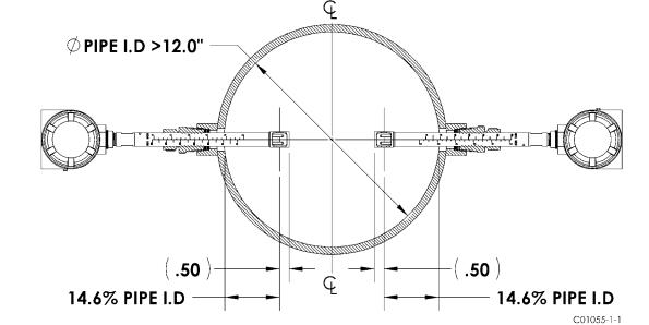
Installed Point Locations
The flow element point locations for a two point averaging system are based from the US EPA – Method 1 Traverse Point recommendations. This method is applicable to gas streams flowing in ducts, stacks, and flues with inside diameters greater than 12 inches. The recommended point locations for a two point averaging system are shown in the diagram below.
Locate and secure the flow elements into position using (0.146 x Pipe I.D. + 0.50 inches) as the location dimension from the pipe I.D. to the end of the flow element.
Fluid Components International LLC |
9 |
INSTALLATION |
ST100 Series Flow Meter |
Flow Element Wiring
The ST/STP102A can be configured with one integral and one remote flow element or with two separate flow elements and remote electronics. Wiring diagrams for these configurations are located in Appendix B. Each of the flow elements on the ST102A/STP102A are connected to the transmitter using an 8 conductor shielded cable as specified in the Instrument Wiring Table 1.
ST/STP102A Electronics Description
The electronic transmitter for the ST/STP102A type instruments provides a two point averaged flow and temperature output on the display and the customer selected output mode, analog or digital.
Analog 4-20mA output: factory default setup
•Output #1 – Two point average Flow
•Output #2 – Two point average Temperature
•Output #3 – Pressure, available on STP models
HART output
•Command 9 – Slot 0, 2, 4: Two point average Flow.
•Command 9 – Slot 5: Two point average Temperature
•Command 9 – Slot 6: Pressure
Fieldbus output
•Flow AI Block – Two point average Flow
•Temperature AI Block – Two point average Process Temperature
•Process Transducer block – index 13, PRIMARY_VALUE (Average FLOW)
•Process Transducer block – index 15, SECONDARY_VALUE (Avrage TEMPERATURE)
Modbus output
• Command 3 – Two point average Flow
Two point average Temperature Pressure, available on STP models Totalizer
10 |
Fluid Components International LLC |

ST100 Series Flow Meter |
INSTALLATION |
Troubleshooting
The “Service Mode” both HART and Foundation fieldbus provide access to the individual sensor output values.
The ST/STP102A electronics transmitter can recognize a disconnected flow element. If this condition is detected, the instrument will indicate a fault condition and display process variables from the sensor that remains connected to the transmitter. The fault will self-correct when the sensor is re-connected.
In-Line Sensor Installation
The sensor can be threaded, flanged or butt weld mounted to the process piping. The specific sensor process connection is customer specified on the Order Information Sheet.
Mount the sensor to the process piping per the application piping requirements. Verify the flow direction arrow is pointed in the correct direction. After the sensor head has been located correctly and tightened into place, verify the process seal does not leak by slowly applying pressure until the normal operation pressure is applied. Check for leaks at the process connection boundary.
Figure 5
Flow Transmitter Electronics Installation
The instrument electronic transmitter can be an integral part of the flow element or it can be mounted remotely using a shielded cable between the flow element and the electronics.
Supply connection wiring must be rated at least 90 °C.
Integral Electronics
The integral electronics package is mounted during the flow element installation process. The integral electronics can be rotated +/- 180 degrees on the top of the flow element insertion pipe. This is done by loosening the lock nut at the base of the enclosure and rotating the enclosure to the preferred orientation. Do not rotate the electronics enclosure more than +/- 180 degrees, damage to internal wiring may result from over rotating the enclosure!
Lock Nut Torque Specification: 30-35 ft-lbs (40-47 N-m)
The Integral electronics should be supported in applications where excessive vibration is present. A mounting bracket is available from FCI to support the electronics when additional support is required.
Fluid Components International LLC |
11 |

INSTALLATION |
ST100 Series Flow Meter |
Figure 6
Remote Electronics
A mounting bracket is supplied when the Transmitter is ordered for remote mounting. The bracket mounting details are shown in Figure 7. below. These details are also available on the Outline Installation Drawings located in appendix A. The electronics can be easily wall or pipe mounted. The mount bracket is designed for .25 inch or M6 mounting hardware. The electronics should be securely mounted to cement or structural support columns or beams. Mounting to plaster is not recommended and does not meet system approval requirements.
Figure 7
12 |
Fluid Components International LLC |

ST100 Series Flow Meter |
INSTALLATION |
Remote Pipe Mounting
Figure 8
Instrument Wiring
The flow transmitter can be powered by 85 – 265 Vac or 24 Vdc as specified in the instrument specification. The electronics cannot be configured to switch between AC and DC power. For 220/265 Vac installations, a neutral reference circuit must be used.
All cable glands and conduit fittings must meet or exceed the area approval rating where the instrument is being installed. The recommended instrument wiring routing is shown in figures 15 and 16.
Figure 15
Fluid Components International LLC |
13 |

INSTALLATION |
ST100 Series Flow Meter |
Figure 16
Connection |
|
10 FT |
50 FT |
|
100 FT |
250 FT |
500 FT |
1000 FT |
||
Power AC or DC |
22 |
22 |
22 |
20 |
|
18 |
16 |
|
||
|
|
|
|
|
|
|
|
|
|
|
Flow Element |
24 |
24 |
24 |
22 |
|
22 |
18 |
|
||
(8 Conductor Shielded) |
|
|
||||||||
|
|
|
|
|
|
|
|
|
|
|
STP Flow Element |
22 |
22 |
22 |
22 |
|
22 |
18 |
|
||
(10 Conductor Shielded) |
|
|
||||||||
|
|
|
|
|
|
|
|
|
|
|
Analog Out (HART) |
16-30 |
16-30 |
16-30 |
16-30 |
|
16-30 |
16-30 |
|
||
|
|
|
|
|
|
|
|
|
|
|
Digital Out |
|
|
|
|
FF-844 H1 (14-30 AWG) |
|
|
|
|
|
Foundation Fieldbus |
|
|
|
|
|
|
|
|
||
|
|
|
|
|
|
|
|
|
|
|
Modbus |
|
|
|
|
RS485 (14-30 AWG) |
|
|
|
|
|
|
|
|
|
|
|
|
|
|||
|
|
|
|
|
|
|
|
|
|
|
|
Instrument Wiring Table 1 - Recommended AWG |
|
|
|
||||||
Analog output maximum load: 600 ohms
Instrument Power Requirements: See Instrument Specifications, page 8.
Instrument Fuse rating and part no:
|
AC Input Power (85 - 265 Vac): |
|
MFR - LITTLEFUSE, 2A TR5 SLO-BLO series 383 (2 Amp rating), part no. 38312000000; FCI part no. 022499-01. |
|
DC Input Power (24 Vdc): |
|
MFR - LITTLEFUSE, 2A TR5 SLO-BLO series 383 (2 Amp rating), part no. 38312000000; FCI part no. 022499-01. |
|
The input power fuse is located on the customer interface board, see figure 16. Instrument power must be turned off when |
|
replacing the fuse. To replace the fuse, unscrew the clear fuse cover and pull the fuse straight out of the holder. Replace the fuse |
|
with the recommended fuse listed above by aligning the fuse pins with the receiving holes located in the fuse holder and pushing |
|
securely into place until the fuse bottoms in the holder. Replace the fuse cover. |
|
|
14 |
Fluid Components International LLC |

ST100 Series Flow Meter |
INSTALLATION |
Reference the following wiring diagrams in Appendix B for specific integral and remote mounted electronics.
Figure B-1 : Integral - AC Input Power, Analog and HART Output |
Figure B-9 : Integral - AC Input Power, Modbus Output |
|
Figure B-2 : Remote - AC Input Power, Analog and HART Output |
Figure B-10 : Remote - AC Input Power, Modbus Output |
|
Figure B-3 : Integral - DC Input Power, Analog and HART Output |
Figure B-11 : Integral - DC Input Power, Modbus Output |
|
Figure B-4 : Remote - DC Input Power, Analog and HART Output |
Figure B-12 : Remote - DC Input Power, Modbus Output |
|
|
|
|
Figure B-5 : Integral - AC Input Power, Foundation fieldbus Output |
Figure B-13 |
: Remote - 8 Conductor Interconnection Cable |
Figure B-6 : Remote - AC Input Power, Foundation fieldbus Output |
|
|
Figure B-7 : Integral - DC Input Power, Foundation fieldbus Output |
Figure B-14 |
: Source - Pulse/Fequency Output |
Figure B-8 : Remote - DC Input Power, Foundation fieldbus Output |
Figure B-15 |
: Sink - Pulse/Fequency Output |
|
|
|
ST102/STP102 |
STP100/STP102 |
|
Figure B-16 : Flow Element Connection - Integral/Remote |
Figure B-18 |
: Remote - 10 Conductor Interconnection Cable |
Figure B-17 : Flow Element Connection - Remote |
|
|
|
|
|
Post Installation Check
Verify all wiring connections are secure and correct to the appropriate wiring diagram. Verify the flow direction arrow on the flow element is pointing in the correct direction. Verify the mechanical process connection is secure and meets the system pressure requirements.
Basic Commissioning and Start-Up
When all wiring and process connections have been verified, apply power to the instrument. The instruments with the LCD will briefly show a welcome screen indicating the software version followed by the normal operation process screen. The normal process screen indicates process flow rate, total flow, temperature and pressure depending on the options ordered. The calibration group and group description are also displayed at the bottom of the screen. Verify the process variable engineering units are correct.
I.R. Sensors
(4 places)
Normal Operation Process Screen
The instrument LCD display functions as a basic HMI setup tool. The four buttons (IR sensors) located at the 3, 6, 9 and 12 o’clock positions on the display provide access to the basic setup parameters. The screen flow is shown in figure 18. The HMI setup menu can be accessed thru the window without removing the electronics enclosure lids. This is done by holding your finger in front of the 12 o’clock sensor for 3 seconds. The LCD acknowledges the button selection by inverting the display characters and background while the button is held.
Fluid Components International LLC |
15 |

INSTALLATION |
ST100 Series Flow Meter |
To enter HMI display menu, cover 12 o’clock button for 3 senconds.
|
|
|
|
|
|
|
... |
|
Welcome Screen |
|
Process Screen |
|
|
T |
|
|
|
|
|
o |
Options |
||
|
|
|
|
Pr |
|||
|
|
|
|
|
|
||
|
|
|
|
|
|
|
|
|
|
|
|
Press and Hold |
Sc o |
Select Group |
|
|
|
|
|
r c |
|||
|
|
|
|
e e |
|
||
|
|
|
|
e s |
Alarm Ack |
||
|
|
|
|
n s |
|||
|
|
|
|
|
Press and Hold |
|
Diagnostics |
|
|
5 second |
|
Top Button for |
|
|
|
|
|
|
|
Top |
|
Set-up |
|
|
|
warmup |
|
|
Button3 secondsfor 3 |
|
|
|
|
|
|
|
SD Card |
||
|
|
|
|
|
|
||
|
|
|
|
|
|
|
|
|
Aug 8, 2009 |
|
|
|
|
|
|
|
Version 1.0 |
|
|
|
|
|
|
|
|
|
|
|
|
|
Select |
|
|
|
|
|
|
|
Group |
|
... |
|
|
|
|
|
|
T |
|
T |
|
T |
|
T |
|
o |
Options |
o |
Options |
o |
Options |
o |
Options |
Pr |
P |
P |
Pr |
||||
|
r |
|
r |
|
|
||
Sc o |
Select Group |
Sc o |
Select Group |
Sc o |
Select Group |
Sc o |
Select Group |
r c |
r c |
r c |
r c |
||||
e e |
|
e e |
|
e e |
|
e e |
|
e s |
Alarm Ack |
e s |
Alarm Ack |
e s |
Alarm Ack |
e s |
Alarm Ack |
n s |
n s |
n s |
n s |
||||
|
Diagnostics |
|
Diagnostics |
|
Diagnostics |
|
Diagnostics |
|
Set-up |
|
Set-up |
|
Set-up |
|
Set-up |
|
SD Card |
|
SD Card |
|
SD Card |
|
SD Card |
|
|
|
|
|
|
|
... |
|
|
Alarm Ack |
|
Diagnostic |
|
Setup |
SD Card |
Figure 18: LCD/HMI Basic Screen Flow
16 |
Fluid Components International LLC |
Loading...