


 Loading...
Installation, Operation and Maintenance
GF90 and GF92
[ |
Model GF90 Insertion |
] |
|
|
Model GF92 In-Line
Doc06EN003229

Notice of Proprietary Rights
This document contains confidential technical data, including trade secrets and proprietary information which is the property of Fluid Components
International LLC (FCI). Disclosure of this data to you is expressly conditioned upon your assent that its use is limited to use within your company only
(and does not include manufacture or processing uses). Any other use is strictly prohibited without the prior written consent of FCI.
Visit FCI on the Worldwide Web: www.fluidcomponents.com
1755 La Costa Meadows Drive, San Marcos, California 92078 USA - 760-744-6950 - 800-854-1993 - Fax 760-736-6250

FLUID COMPONENTS INTERNATIONAL LLC |
http://www.fluidcomponents.com |
|||
1. |
General Information |
Description ............................................................................................................ |
|
1 |
|
|
Flow Element ........................................................................................................ |
|
1 |
|
|
Flow Transmitter ................................................................................................... |
|
1 |
|
|
Technical Specifications ....................................................................................... |
|
2 |
2. |
Quick Start Guide |
Pre-Installation ...................................................................................................... |
|
5 |
|
|
Flow Element Installation ...................................................................................... |
|
5 |
|
|
Wiring Preparation ................................................................................................ |
|
6 |
|
|
Wiring the Instrument ............................................................................................ |
|
6 |
|
|
Instrument Operation............................................................................................. |
|
8 |
3. |
Installation |
Receiving/Inspection ............................................................................................. |
|
11 |
|
|
Packing/Shipping/Returns..................................................................................... |
|
11 |
|
|
Factory Calibration Note ....................................................................................... |
|
11 |
|
|
Pre-Installation Procedure .................................................................................... |
|
11 |
|
|
Install Flow Element .............................................................................................. |
|
13 |
|
|
Install Flow Transmitter ......................................................................................... |
|
16 |
|
|
Customer Wiring ................................................................................................... |
|
20 |
|
|
Serial Communication Option ............................................................................... |
|
20 |
|
|
HART Option Installation ...................................................................................... |
|
21 |
|
|
Foundation Field Bus ............................................................................................ |
|
24 |
|
|
Isolated Output Option and 4-20 mA Adjustment ................................................. |
|
25 |
|
|
LT81 Series Upgrade Information......................................................................... |
|
26 |
|
|
Apply Power .......................................................................................................... |
|
26 |
4. |
Operation |
Introduction ............................................................................................................. |
|
27 |
|
|
Start-UpProcedure ................................................................................................. |
|
27 |
|
|
Operation................................................................................................................ |
|
27 |
|
|
AdvancedFeatures ................................................................................................. |
|
41 |
|
|
External Input Auto-Select Procedure ................................................................... |
|
53 |
|
|
Optional Veri-Cal In-Situ Calibration Verfication .................................................... |
|
54 |
|
|
Optional Purge System ........................................................................................ |
|
59 |
|
|
Two Point Averaging System Option ..................................................................... |
|
60 |
5. |
Maintenance |
Maintenance ........................................................................................................... |
|
65 |
6. |
Troubleshooting |
Introduction ............................................................................................................. |
|
67 |
|
|
TroubleshootingEquipment..................................................................................... |
|
67 |
|
|
QuickTroubleshooting ............................................................................................ |
|
67 |
|
|
In-Depth Troubleshooting - Standard GF90/GF92 Flow Element.............................. |
68 |
|
|
|
In-Depth Troubleshooting - GF90 with VeriCal Flow Element ................................... |
|
69 |
|
|
In-Depth Troubleshooting - The Flow Transmitter ..................................................... |
|
71 |
|
|
In-Depth Troubleshooting - The Installation .............................................................. |
|
72 |
|
|
In-Depth Troubleshooting - The Process ................................................................. |
|
72 |
|
|
OtherTroubleshooting............................................................................................. |
|
73 |
|
|
Verifying Delta R's .................................................................................................. |
|
74 |
|
|
Repair..................................................................................................................... |
|
75 |
|
|
DefectiveParts ....................................................................................................... |
|
75 |
|
|
CustomerService ................................................................................................... |
|
75 |
7. Appendices |
Appendix A. Outline Drawings and Wiring Diagrams ............................................... |
|
77 |
|
|
|
Appendix B. Glossary of Terms .............................................................................. |
|
83 |
|
|
Appendix C. Declaration of Conformity .................................................................... |
|
87 |
|
|
Appendix D. Customer Service ............................................................................... |
|
93 |
Doc. No. 06EN003229 Rev. H |
GF Series Flow Meter Models GF90/GF92 |
FLUID COMPONENTS INTERNATIONAL LLC |
http://www.fluidcomponents.com |
THIS PAGE INTENTIONALLY LEFT BLANK
GF Series Flow Meter Models GF90/GF92 |
Doc. No. 06EN003229 Rev. H |
|
FLUID COMPONENTS INTERNATIONAL LLC |
http://www.fluidcomponents.com |
||
|
|
|
|
|
|
|
1. General Information |
|
|
Description |
This document describes the procedures required to install, operate, maintain, and troubleshoot the |
|||
|
|
Model GF90 and GF92 Flowmeters. There are a wide range of possible configurations and information |
||
|
|
related to the optional features. The flowmeter is composed of a remote thermal dispersion sensing |
||
|
|
device (flow element) interconnected to a microprocessor-based electronics control and display package |
||
|
|
(flow transmitter). The flow element can be attached directly to the flow transmitter (local instrument) |
||
|
|
or it can be connected to the flow transmitter with a cable of up to 1000 feet or 300 meters (remote |
||
|
|
instrument). |
|
|
|
|
The instrument is designed to operate in gaseous mass flow metering environments. The flowmeter is |
||
|
|
factory calibrated to handle a range of flows. |
|
|
|
|
|
||
Flow Element |
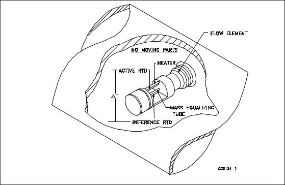
The flow element consists of 4 thermowells. The thermowells are hollow metal tubes that are braised |
|||
together to make 2 pairs of thermowells. One thermowell pair contains the active Resistance Temperature Detector (RTD) and a heater. The other thermowell pair contains the reference RTD and an empty thermowell for thermal mass equalization. Figure 1 shows the flow element.
|
Figure 1. Cut-Away View of the Flow Element |
|
|
Flow |
The other component of the flowmeter is the flow transmitter. The basic functions of the flow |
Transmitter |
transmitter are to provide power to the flow element, measure the Differential Temperature (∆ T) |
|
between the two RTDs as a function of resistance, amplify and linearize the Differential Resistance |
|
(∆ R) measurement of the flow element input signal and to provide an output signal. |
|
This output signal is calibrated to the flow rate as a function of velocity, standard volume or mass flow. |
|
To perform these functions, microprocessor-based electronic circuitry is employed to acquire the analog |
|
voltage signals from the RTDs, digitize and interpret the information. |
|
The microprocessor-based electronics provides maximum flexibility and ease of operation with a menu- |
|
driven selection of control, monitoring, display and driver options. |
Doc. No. 06EN003229 Rev. H |
1 |
GF Series Flow Meter Models GF90/GF92 |

FLUID COMPONENTS INTERNATIONAL LLC |
http://www.fluidcomponents.com |
The flow element consists of two pairs of thermowells of the same size, shape and mass. One pair contains a platinum RTD and a heater element. The other pair contains one RTD. The RTD located next to the heater element is called the active RTD. The other RTD is referred to as the reference RTD. Since the active RTD is adjacent to the heater, the temperature at the walls of the thermowell are always above the temperature of the process media. The temperature at the reference RTD is the temperature of the process media. When the process media is flowing past the active RTD a quantity of heat is carried off into the flow stream. The amount of heat taken from the active RTD is a function of the process media mass flow rate. A ∆ T exists between the two pairs of thermowells and a proportional ∆ R exists between the active and the reference RTDs. The ∆ R is measured by the flow transmitter. The relationship of ∆ T to the mass flow rate is calculated by the flow transmitter and is converted into a signal or is sent to the flow transmitter's display.
Technical
Specifications
Gas Mass Flow Measurement:
GF90: In ducts or pipes sizes with a minimum 2.0 inch (5.1 cm) nominal inside diameter. GF92: In pipe lines or tubing sizes from 0.125 to 3 inches (0.3175 to 7.62 centimeters).
Flow Elements
Process Connection:
GF90: 1 inch male NPT standard. Flange connections and field retractable packing gland assemblies available.
GF92: 3/4 inch female NPT standard. 1.0, 1.5, 2.0 and 3.0 inch male or female NPT, flange connections available.
Insertion Length — GF90: Variable length. Specify insertion “U” length (dimension from the process connection to the tip of the flow element) to extend the tip of the flow element 1 inch (2.5cm) past the centerline of the process pipe.
Body Length — GF92: 7.25 inches (18.4cm) for 1 inch flow tubes; 12.0 inches (30.5 cm) for 1.5 to 3 inch (3.81 to7.62 cm) pipe spool pieces. Variable A-lengths available.
Flow Element Material: All wetted surfaces are 316 stainless steel with nickel braze. Corrosionresistant alloys are available with factory specified all welded construction or compatible brazes.
Flow Element Range:
GF90: 0.25 to 1600 SFPS for most gases (ft/sec at a standard temperature of 70° F and pressure of 14.7 psia) or 0.08 to 487.7 NMPS [m/sec at a normal temperature of 21.1°C and
pressure of 1.013 bar (absolute)].
GF92: 0.006 to 2000 SCFM for most gases (ft3/min at a standard temperature of 70°F and pressure of 14.7 psia) or 0.01 to 3398 Nm3/h [m3/ hr at a normal temperature of 21.1°C and
pressure of 1.013 bar (absolute)].
Actual velocity for both the GF90 and GF92 must be limited to a maximum of 200 feet per second (60.96 meters per second).
Temperature Range: -50° F to +350°F (-45° C to +176.7°C) with the standard temperature flow element. The GF90 is available in a High Temperature Flow Element configuration for service in process temperatures from -100° F to +850° F (-73.3° C to +454.4°C).
Operation Pressure: Up to 1000 psig [68.9 bar (gauge)].
Transmitter
Signal Output:
Analog: Two independent signal outputs available that may be field set from the following listed selection:
4-20 mA, 600 ohms maximum load
0-10 Vdc, 5000 ohms minimum load
0-5 Vdc, 2500 ohms minimum load
1-5 Vdc, 2500 ohms minimum load Digital: RS-232C (EIA-232) serial port.
Switch Points (Dual Alarms): The switch points may be field set by programming the GF90 or GF92 to alarm at high, low or windowed flow or at high, low or windowed process temperature.
GF Series Flow Meter Models GF90/GF92 |
2 |
No. 06EN003229 Rev. H |
FLUID COMPONENTS INTERNATIONAL LLC |
http://www.fluidcomponents.com |
Technical Specifications (Cont’d)
Relays: Two Relays independently adjustable: 2 amps bifurcated gold plated DPDT contacts, 0-2.0 amps at 28 Vdc or 115 Vac resistive, 0.1 volts at 230 Vac resistive. 0 amps (or Dry) rating is good if load is kept below 30mA.
Slave Relay Energization Terminals: Customer provided relay may be energized at programmable values connecting to points on the output terminal strip.
+Ext Relay: 20 Vdc, sourcing up to 100 mA total both relay outputs. -Ext Relay: Open/Ground (switching).
Power Input: 115 Vac, ±15 Vac, 16 watts maximum or 230 Vac, ±30 Vac, 50/60Hz, 16 watts maximum; or 24 Vdc, -2 and +6 Vdc, 16 watts maximum as selected by the power input switch and terminal selection.
Indicator Display & Built-In Keypad: 4 lines by 20 character liquid crystal display that may be programmed to indicate flow rate, total flow, temperature, and switch point status in customer determined English or Metric (SI) values. Keypad permits easy touch programming to change zero, span, switch points, and units of measurement and for instrument verification, trouble shooting and other critical instrument functions.
Electrical Enclosures
Fiberglass NEMA/CSA Type 4X is standard. All aluminum and stainless steel enclosures are rated for hazardous location use (Class I and II, Division 1 and 2, Groups B, C, D, E, F and G; and EEx d IIC) and resists the effect of weather and corrosion (NEMA/CSA Type 4X and equivalent to IP66).
Electrical Connection: 1 inch female NPT.
Temperature Range: 0°F to +150°F (-18°C to +65.6°C).
Flow
Accuracy: ±1% reading + 0.5% full scale. Repeatability: ±0.5% reading or better.
Turndown Ratio: Field set to within specified flow range from 2:1 to 1000:1. Turndown ratios up to 1000:1 are possible in some applications. Signal output may be field set to be zero or non-zero based. Up to three independent calibrations may be stored in the GF Series transmitter and selected via the built-in keypad, RS-232C Serial Port or Auxiliary Input Terminal (4-20 mA).
Calibration Adjustment: Up to three independent calibration groups are available. Each group is precisely calibrated at the factory in accordance with the submitted Application Data Sheet to turndown ratios as high as 1000:1. Most calibrations are performed in the actual process fluid and process conditions described by the customer’s specification. Adjustment to zero and span are made easily in the field by using the keypad to input revised flow or temperature range information.
Temperature
Accuracy: ±2°F (±1.1°C ). Valid only above minimum flowing conditions of 5 SFPS (1.5 NMPS).
Repeatability: ±1°F (±0.55°C).
System Approvals
Factory Mutual Research (FM), CSA, CE Mark, CENELEC, CRN and ATEX.
Doc. No. 06EN003229 Rev. H |
3 |
GF Series Flow Meter Models GF90/GF92 |
FLUID COMPONENTS INTERNATIONAL LLC |
http://www.fluidcomponents.com |
THIS PAGE INTENTIONALLY LEFT BLANK
GF Series Flow Meter Models GF90/GF92 |
4 |
No. 06EN003229 Rev. H |
FLUID COMPONENTS INTERNATIONAL LLC |
http://www.fluidcomponents.com |
|
|
2. Quick Start Guide
Pre-Installation
To get the best results from the instrument, the sensor should be located 20 pipe diameters down stream from any flow disturbance (valve, pipe elbow, etc.) and 10 pipe diameters upstream from any disturbance.
The outside of the instrument has tags which show the model number, tag number (if noted on the customer’s order) and serial number along with other important safety information. Compare this information with the appropriate pipe installation drawings and calibration sheets to verify the instrument is the correct configuration.
Verify that the serial numbers on the enclosure(s) tag(s), flow element and electronics match. The instrument may not work if the serial numbers are miss-matched.
The recommended installation/troubleshooting tools are:
1 ea. |
Open-ended wrench to fit the NPT connection |
1 ea. |
Open-ended wrench to fit the flanged fitting nuts and bolts |
1 ea. |
Small flat blade screw driver for manipulating potentiometers |
1 ea. |
Medium flat blade screwdriver for tightening connections |
1 ea. |
Medium phillips head screwdriver for tightening connections |
1 ea. |
3 mm Allen wrench |
1 ea. |
Measuring tape for proper flow element placement |
1 ea. |
DVM for Ohm/Voltage measurements |
Flow Element |
Installation |
Example of GF90 Flow Meter (See Appendix A for Specific Diagrams)
Install the flow element, with the flow arrow pointing in the direction of media flow. The element should be in the center line of the process pipe or rectangular duct as shown above.
If the NPT option is used, see Page 13 for installation instructions.
If the flanged option is used, see Page 13 for installation instructions.
If the GF92 in-line option is used, see Page 14 for installation instructions.
NOTE: ST98 type flow element only inserts 0.50 inches past centerline. See VeriCal System
Diagram on page 54.
Doc. No. 06EN003229 Rev. H |
5 |
GF Series Flow Meter Models GF90/GF92 |

FLUID COMPONENTS INTERNATIONAL LLC |
http://www.fluidcomponents.com |
Wiring
Preparation
CAUTION:
Only qualified personnel are to wire all responsibilities for safe practices
or test this instrument. The operator assumes while wiring or troubleshooting.
ALERT: The instrument contains electrostatic discharge (ESD) sensitive devices. Use standard ESD precautions when handling the flow transmitter.
Before the instrument is opened to install the wiring, FCI recommends that ESD precautions be observed. See Page 11 for ESD instructions.
Wiring the
Instrument
This section wires the transmitter inputs, outputs and interconnection cabling for the instrument. Route the output wiring through the opposite port from the power wiring. The maximum gauge of wire to use is 16 AWG. See Table 1 on Page 16 and Table 2 on Page 17 for the maximum distance that wires can be run.
Wiring the Flow Element
Connect a shielded, 8 wire cable between the transmitter and the local enclosure terminal strip as shown below. Be sure the shield (ground wire) is connected to JP3 GND along with the wire from terminal block terminal 2. Do not connect the shield to the local enclosure (leave it floating).
Alternate 8 wire, ST98 Type Flow Element wiring shown in VeriCal and 2 point Averaging System sections, see Operations Section 4.0.
Local Enclosure Wiring Diagram
|
|
|
|
|
|
|
|
|
|
|
|
|
|
|
Flow Element |
Transmitter |
|
|
|||
|
|
|
Terminal Block |
JP3 (Terminal No.) |
|
|
||||
|
|
Terminal 5 (ACT) |
ACT SEN (4) |
|
|
|
|
|||
|
|
Terminal 5 (ACT) |
ACT EXC (6) |
|
|
|
|
|||
|
|
Terminal 4 (GND SEN) |
GND SEN (2) |
|
|
|
|
|||
|
|
Terminal 3 (REF) |
REF SEN (3) |
|
|
|
|
|||
|
|
Terminal 3 (REF) |
REF EXC (5) |
|
|
|
|
|||
|
|
Terminal 2 (GND) |
GND |
(1) |
|
|
|
|
||
|
|
Terminal 1 (HTR) |
HTR EXC (7) |
|
|
|
|
|||
|
|
Terminal 1 (HTR) |
HTR SEN (8) |
|
|
|
|
|||
|
|
|
Flow Element Wiring Table |
|
|
|
|
|
||
Flow Element Terminal Block |
|
|
|
|
|
|
|
|
||
|
|
|
|
|
|
|
Connector JP3 |
|||
|
|
|
|
|
|
|||||
|
|
|
|
|
||||||
(Be sure the jumper is in place |
|
|
|
|
|
|
||||
Terminal 2 to terminal 4.)
GF Series Flow Meter Models GF90/GF92 |
6 |
Doc. No. 06EN003229 Rev. H |
FLUID COMPONENTS INTERNATIONAL LLC |
http://www.fluidcomponents.com |
Wiring the Instrument’s Signal Output to the Customer Application:
For Current Output: 4 - 20 mA; connect a positive wire to + I OUT and a negative wire to OUT COM.
For Voltage Output: 0 - 5, 0 - 10 or 1 -5 Vdc; connect a positive wire to + E OUT and a negative wire to OUT COM.
Analog Output 2 is connected in a similar manor as Analog Output 1. ( For Voltage Output: 0 - 5, 0 - 10 or 1 -5 Vdc; connect a positive wire to + E OUT2 and a negative wire to
OUT 2 COM. For Current Output: 4 - 20 mA; connect a positive wire to + I OUT2 and a negative wire to OUT 2 COM.)
Customer Connections Analog Output Diagram |
Analog Output |
|
Plug Location |
Alert: Either voltage or current from the Analog Outputs can be connected to the customer application, not both. (Example: Voltage and current from analog output 1 cannot be connected.) However, one Analog Output can be wired for current and the other Analog Output can be wired for Voltage.
Wiring the Output Relays:
The instrument contains two sets of alarm output relays (connectors JP4 Relay Output 1, and JP5 Relay Output 2). They can be wired by the customer. (NO = Normally Open, NC = Normally Closed, Pole = Common)
|
|
|
|
|
|
|
|
|
|
|
|
|
|
|
|
|
|
|
|
|
|
|
|
|
|
|
|
|
|
|
|
|
|
|
|
|
|
|
|
|
|
|
|
|
|
|
|
|
|
|
|
|
|
|
|
|
|
|
|
|
|
|
|
|
|
|
|
|
|
|
|
|
|
|
|
|
|
|
|
|
Output Relay Wiring Diagram |
|
Connectors JP5 and JP4 |
||||
Doc. No. 06EN003229 Rev. H |
7 |
GF Series Flow Meter Models GF90/GF92 |

FLUID COMPONENTS INTERNATIONAL LLC http://www.fluidcomponents.com
Wiring the Input Power:
Caution: FCI recommends placing an ON/OFF switch in line with the power source. When JP1 is connected to the power source the instrument is ON.
AC or DC power can be used to operate this instrument. For best results route the output signal wiring through the left port of the instrument enclosure and the power input wiring thorough the right port. See the wiring table on Page 16 to determine the minimum size of wiring to be used versus the length of the wire run to the power source.
115 or 230 VAC Power Option
The input power can be switched from 115 Vac to 230 Vac by moving switch S1 to the correct setting. (The instrument requires only AC or DC to be connected, not both.) Connect the hot side of the AC Line to AC Line, the neutral side to AC NEUT, and ground to EARTH GND. (Do not connect the local enclosure shield wire to the EARTH GND on this plug.)
24 VDC Power Option
If DC power is used, the AC Input and switch S1 are not pertinent. Wire the positive 24 volt input to +24V. Connect the negative wire to DC GND.
Switch S1
Connector JP1
|
Input Power Location |
|
|
|
Input Power Wiring Diagram |
||
|
|
||||||
Instrument |
The instrument has been configured and calibrated to custom specifications. In-depth programming |
||||||
Operation |
of the instrument in the field should not be necessary. |
|
|
|
|
||
|
|
|
|
|
|
|
|
|
Apply power to the instrument. Wait 10 minutes for the instrument to stabilize. During this period |
||||||
|
the instrument may indicate a high flow condition. When the instrument is powered up, the |
||||||
|
instrument will display an initialization sequence. Then the instrument will display the normal |
||||||
|
operation information. Shown below is the normal operation window. |
||||||
|
|
|
|
|
|
|
|
|
|
Flow Rate |
|
|
|
Flow Units |
|
|
Output Channel # |
CH1: 5056.3 SCFM |
|
Process Temperature |
|||
|
CH2: 71.2 °F |
|
|
|
Totalizer (If Enabled) |
||
|
|
|
|
|
|||
|
|
Σ = |
435226 SCF |
|
|
|
|
|
|
(grp1)(ed)(norm)(m) |
|
|
|
Sample (Flashes) Rate |
|
|
|
|
|
|
|||
|
Calibration Group # |
Relay Status |
Mode |
|
|
||
|
|
|
|
|
|
||
|
|
Normal Operation Window |
|
|
|||
GF Series Flow Meter Models GF90/GF92 |
8 |
Doc. No. 06EN003229 Rev. H |
FLUID COMPONENTS INTERNATIONAL LLC |
http://www.fluidcomponents.com |
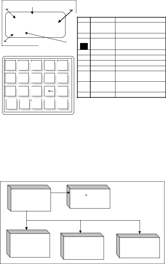
MenuControl
The prompt line displays appropriate key strokes for the required menu level. If a key is pressed that is not valid for that menu, Invalid Response will flash briefly across the prompt line. The key pad and key assignments are shown below:
|
Title |
|
|
|
|
|
||
Menu Level |
Available Selections |
|
|
|
||||
|
3.1.2 STD VOLUME |
|
KEY |
KEY NAME |
ACTION |
|||
1=Cu feet |
3=Cu meter |
|
||||||
|
0-9 |
Numeric |
Selects options and enters |
|||||
3=Liters |
|
|
|
|||||
|
|
|
numbers. |
|||||
(CF)? |
|
|
|
|
|
|||
|
|
|
Y |
Yes |
Enter a yes response |
|||
|
|
|
|
|
||||
Current Selection Prompt Line |
|
• |
No or (N)ext |
Enter a no response or |
||||
|
Display Characteristics |
|
N |
scroll to next screen |
||||
|
|
|
|
|||||
|
|
- |
Minus |
Enter a minus sign |
||||
|
|
|
|
|
||||
|
|
|
|
|
|
Decimal Point |
Enter a decimal point |
|
1 |
2 |
3 |
Y |
N |
|
Back Space |
Moves cursor back one space |
|
P |
(P)revious |
Scrolls to the previous screen |
||||||
|
|
|
|
|
||||
|
|
|
_ |
|
ENTR Enter |
Enters a numeric value or |
||
4 |
5 |
6 |
. |
response |
||||
|
|
|||||||
|
|
|
|
|
HOME Home |
Returns to the Main Menu or |
||
7 |
8 |
9 |
|
P |
escapes from routines |
|||
|
|
|
||||||
|
UP |
Up |
Move current menu up on level |
|||||
|
|
|
|
|
||||
ENTR |
0 |
# |
HOME |
UP |
|
Key Assignments |
||
|
|
|
||||||
|
|
Key Pad |
|
|
|
|
|
|
At any time, the HOME key can be pressed and the main menu will display. HOME can be used to escape from most routines, or restart a progression into the menu structure.
When (N)ext is displayed on the prompt line, more than two menu selections are available. Press N to scroll through all the selections.
The UP key, will back-out of a menu level. The menu moves back one level each time the UP key is pressed. The UP key only functions when UP is displayed on the prompt line.
To make a selection, press the numeric key associated with the desired menu selection. The selection does not have to be displayed, but it must be one of the available selections.
The quick operation menu is shown below:
0.0 MAIN MENU |
|
CH1: 5056.3 SCFM |
|
QUICK |
||
1 |
= Normal Operation |
|
CH2: 71.2F |
OPERATION |
||
2 |
= Port Setup |
|
Σ= 435226 SCF |
|||
3 |
= Display Setup |
|
(grp1) (dd) (mode N) (m) |
|
MENU |
|
4 |
= Miscellaneous |
|
Normal Operation |
|
||
|
|
|
|
|
||
2.0 PORT SETUP |
3.0 DISPLAY SETUP |
|
|
|||
1 |
= Analog Output |
4.0 MISCELLANEOUS |
||||
2 |
= Relays |
1 |
= Flow Setup |
1 |
= Set Group |
|
3 |
= Comm Output |
2 |
= Temperature Setup |
2 |
= Corrector Setup |
|
4 |
= Aux Input |
3 |
= Totalizer Setup |
3 |
= Password Setup |
|
|
|
|
4 |
= Sample Rate |
|
|
Doc. No. 06EN003229 Rev. H |
9 |
GF Series Flow Meter Models GF90/GF92 |
FLUID COMPONENTS INTERNATIONAL LLC |
http://www.fluidcomponents.com |
THIS PAGE INTENTIONALLY LEFT BLANK
GF Series Flow Meter Models GF90/GF92 |
10 |
Doc. No. 06EN003229 Rev. H |

FLUID COMPONENTS INTERNATIONAL LLC |
http://www.fluidcomponents.com |
||
|
|
|
|
|
|
3. |
Installation |
Receiving/ |
• |
Unpack carefully. |
|
Inspection |
• Verify that all items in the packing list are received and are correct. |
||
|
• |
Inspect all instruments for damage or contaminants prior to installation. |
|
If the above three items are satisfactory, proceed with the installation. If not, then stop and contact a customer service representative.
Packing/ |
These issues are addressed in Appendix D - Customer Service. |
|
Shipping/ |
|
|
Returns |
|
|
|
|
|
Factory |
The instrument is factory calibrated to the flow range specified in the order. There is no need to |
|
Calibration |
perform any verification or calibration steps prior to installing and placing the instrument in service. |
|
Note |
|
|
Pre-Installation |
|
|
Procedure |
|
|
|
CAUTION: Only qualified personnel should install this instrument. Install and follow safety |
|
|
|
procedures in accordance with the current National Electrical Code. Ensure that power |
|
|
is off during installation. Any instances where power is applied to the instrument will be |
|
|
noted in this manual. Where the instructions call for the use of electrical current, the |
|
|
operator assumes all responsibility for conformance to safety standards and practices. |
|
ALERT: |
The instrument is not designed for weld-in-place applications. Never weld to process |
|
|
connection or a structural support. |
Damage resulting from moisture penetration of the enclosure(s) is not covered by product warranty.
The flow transmitter contains electrostatic discharge (ESD) sensitive devices. Use standard ESD precautions when handling the circuit board assemblies. See below for ESD details.
Use Standard ESD Precautions
When opening an instrument enclosure or handling the flow transmitter use standard ESD precautions. FCI recommends the use of the following precautions: Use a wrist band or heel strap with a
1 megohm resistor connected to ground. If the instrument is in a shop setting there should be static conductive mats on the work table and floor with a 1 megohm resistor connected to ground. Connect the instrument to ground. Apply antistatic agents to hand tools to be used on the instrument. Keep high static producing items away from the instrument such as non-ESD approved plastic, tape and packing foam.
The above precautions are minimum requirements to be used. The complete use of ESD precautions can be found in the U.S. Department of Defense Handbook 263.
Prepare or Verify the Flow Element Location
Prepare the process pipe for installation or inspect the already prepared location to ensure that the instrument will fit into the system.
Mount the flow element at least 20 diameters downstream and 10 diameters upstream from any bends or interference in the process pipe or duct to achieve the greatest accuracy.
Doc. No. 06EN003229 Rev. H |
11 |
GF Series Flowmeter Models GF90/GF92 |

FLUID COMPONENTS INTERNATIONAL LLC |
http://www.fluidcomponents.com |
Verify Dimensions
The GF90 Insertion Models have an adjustable insertion length ferrule until it is locked into position. Verify all dimensions before locking the fitting in place. See the appropriate figures in Appendix A.
NOTE: Two types of ferrules are available. One type of ferrule is made from Teflon. This can be tightened and loosened repeatedly at different places on the flow element. The other type of ferrule is made from Stainless Steel. This ferrule can only be tightened in one place on the flow element. The Stainless Steel Ferrule makes an indentation into the flow element for a more firm fit.
The GF92 In-Line Model's flow element has a tube or pipe length and diameter that is specified at the time of order. This dimension should be double checked with the process line.
Verify Flow Direction
Verify the flow direction and orientation of the flow element before placing it into the flow media. The GF90’s flow element has flat areas machined on the flow element near the enclosure end of the flow element. Etched on the flow element is a flow arrow indicating the direction of flow. See Figure 2. Align the GF90’s flow element during installation so the flat areas are parallel to the direction of the process media flow, and the flow arrow points in the direction of process media flow. A flow direction arrow is etched on the in-line GF92’s tube or pipe and should be pointing in the direction of flow. Failing to install the flow element correctly will reduce the accuracy of the flow meter.
Verify Serial Numbers
Verify the serial number of the flow element and electronics. The instrument’s flow element has a serial number near the flat machined area or flow arrow. The same number is on the main electronics circuit board, and on the tag of the electronics enclosure. These numbers have to match because the flow element and the electronics are a matched set. Failure to observe serial numbers will cause inaccurate readings.
Figure 2. Model GF90 Insertion Flanged Flow Element Showing Orientation
GF Series Flowmeter Models GF90/GF92 |
12 |
Doc. No. 06EN003229 Rev. H |

FLUID COMPONENTS INTERNATIONAL LLC |
http://www.fluidcomponents.com |
Install Flow
Element
ALERT: Do not overtighten the flow element. The RTD's can be damaged if the flow element is forced into the far wall of the pipe or vessel.
Cable Glands and Conduit Fittings
All cable glands and conduit fittings, including conduit plugs, must meet or exceed the area approval where unit is being installed.
NOTE: The instrument accuracy will be reduced if the media flow is reversed from the flow direction of the flow arrow machined on the flow element or if the flats are not parallel, within ±1° of the flow direction.
Select one of the following installation procedures which is applicable to the unit being installed.
GF90 Flange Mount
The flange mount flow element is shown in Figure 2. Attach the process mating flange with care. The correct orientation of the flow element must be maintained to ensure the calibrated accuracy.
•Verify that the process media flow is in the same direction as the arrow on the FLAT.
•Apply the appropriate gasket and/or sealant to flange mount as required.
•Mate flow element flange to process mount keeping flat oriented properly.
•Attach with bolt, two flat washers, lock washer and nut for each bolt hole, apply lubricant/sealant to male threads and torque. Refer to ANISI B16.5 specifications.
GF90 NPT Pipe Thread Mount
ALERT: DO NOT change the orientation of the flow element in the enclosure as the interconnecting RTD and heater wiring could be stressed and damaged. DO NOT apply any torque to the flow element enclosure - only apply to NPT pipe surface itself.
NOTE: When mounting the flow element to the process pipe, it is important that a lubricant/ sealant is applied to the male threads of all connections. A lubricant/sealant compatible with the process environment should be used. All connections should be tightened firmly. To avoid leaks do not overtighten or cross-thread connections.
The pipe thread configuration is shown in Figure 3. Apply sealant compatible with the process media to male threads. Carefully insert into process mount. Threads are right-handed. Tighten with an openend wrench on the hexagonal surface provided. Rotate until snug and continue to turn until flat is horizontal to process flow.
Figure 3. Model GF90 Insertion NPT Flow Element
Doc. No. 06EN003229 Rev. H |
13 |
GF Series Flowmeter Models GF90/GF92 |

FLUID COMPONENTS INTERNATIONAL LLC |
http://www.fluidcomponents.com |
GF90 Adjustable / Retractable Flow Element Assembly
Applications involving the use of a packing gland (low, medium or high pressure) should refer to the drawings located in Appendix A for additional detail.
•NPT and flange packing gland mounts are available. The valve assembly with appropriate connections are customer supplied. Follow the pipe thread procedure or the flange procedure as shown on the previous page.
•Then tighten packing nut until internal packing is tight enough so that the friction fit on the shaft is adequate to prevent leakage but not prevent the shaft from sliding. Position the flat horizontal with arrow in direction of process flow.
•Proceed to insert the flow element into process media line. For the medium pressure packing gland use the adjusting nuts on the all-thread to pull the flow element into proper predetermined depth position.
•Tighten the opposing lock nuts on the all-threads. Tighten the packing nut another 1/2 to 1 turn until tight (approximately 65 to 85 ft-lbs torque).
•Rotate split ring locking collar to line up with connecting strap welded to packing nut. Tighten the two 1/4-28 hex socket cap screws on the split ring locking collar. Open valve - check for process media leakage.
•Reverse these steps for removal.
GF90 2 Inch (50 mm) Pipe Mount (Inside Diameter)
Use a tee-pipe configuration for applications where the inside diameter of the process pipe is
2 inches (50 mm). See Figure 4 for an illustration. The flow element active area is approximately 1 inch (25.4 mm) long, (the inactive area is also approximately 1 inch long), so it is impractical to place the flow element in a line of less than 2 inches (50 mm) inside diameter without loss of accuracy and reliability. Install the flow element per connection procedure for pipe thread, flange, or packing gland assembly as applicable.
Figure 4. 2 Inch (51 mm) Pipe Mount
GF90/GF92 Pigtail
Insert the instrument into the process and connect the flow element per the wiring diagram in
Figure 50. Be sure to the correct diagram for either the cable or wire configuration.
GF Series Flowmeter Models GF90/GF92 |
14 |
Doc. No. 06EN003229 Rev. H |

FLUID COMPONENTS INTERNATIONAL LLC |
http://www.fluidcomponents.com |
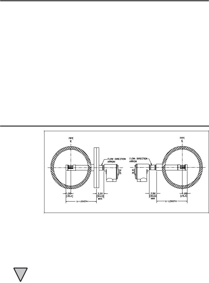
GF92 In-line Body Length Verification
The GF92 flow element's mounting shape is a cylindrical pipe, with a customer specified "A" length (see Figures 5 and 6) with process connections as ordered. The minimum recommended clearance length in the process media pipe is 7.25 inches (184 mm).
Figure 5. Correct Orientation
GF92 Flange Mount
For flange mount flow element, attach the process mating flange with care. The correct orientation of the flow element must be maintained to ensure the calibrated accuracy.
Figure 6. Flange Connections
GF92 Butt Weld
When welding the butt weld option into the process line, be sure the flow arrow with the machined flat is facing up and the arrow is in the direction of flow. Also, be sure the wires to the remote enclosure are disconnected from the integral enclosure. Ground the flow element before welding. Do not weld anything to either the remote or local enclosures.
GF92 NPT Connection (Threaded Male or Female)
Apply sealant to male threads. Carefully place in the process media line with the machined flat facing up, flat and level within ±2° for best results. The instruments threads are right-handed, tighten the process connections.
Doc. No. 06EN003229 Rev. H |
15 |
GF Series Flowmeter Models GF90/GF92 |

FLUID COMPONENTS INTERNATIONAL LLC |
http://www.fluidcomponents.com |
Remote Hardware Location (GF90 and GF92)
The outline dimensions shown in Appendix A show the physical dimensions for the proper mounting of the flow element and transmitter electronics enclosure. Select a location for the flow transmitter within 1000 feet (310 M) of the flow element. Pigtail flow elements can not be located more than
10 feet (3 M) from the flow transmitter. This location should be easily accessible with enough room to unscrew the enclosure top at any time. Secure the enclosure to a surface capable of providing support. Use appropriate hardware to secure the enclosure.
Install Flow
Transmitter
CAUTION: Ensure that all power is off before wiring any circuit.
ALERT: In applications where the flow element is located in an explosive environment, isolate the conduit before it leaves the environment. A potting Y may be used to provide the isolation.
Cable Glands and Conduit Fittings
All cable glands and conduit fittings, including conduit plugs, must meet or exceed the area approval where unit is being installed.
NOTE: FCI recommends installing an input power disconnect switch and fuse near the flow transmitter to interrupt power during installation, maintenance, calibration, and troubleshooting procedures.
Make all electrical connections through the 3/4 inch NPT ports in the enclosure. Run all electrical cables through appropriate conduit or protective sheathing.
Minimum Wire Size
If the instrument is used in a remote configuration, a shielded, 8 conductor cable is to be used between the local and remote enclosures. Table 1 shows the smallest (maximum AWG number) copper wire that should be used in the cable and in other wiring. Use a lower gauge of wire (larger diameter) for less of a voltage drop. Contact FCI concerning greater distances than those listed in the table. The sensing element cable for the remote option must be shielded. The maximum wire size of the nonpower connectors in the instrument is 16 AWG (1.47 mm). The maximum wire size of the power connectors in the instrument is 12 AWG (2.36 mm). Table 2 shows the AWG to millimeter conversions.
Table 1. Maximum AWG Number
Connection |
Maximum Distance for AW G |
|
|
||||
10 FT. |
50 FT. |
100 FT. |
250 FT. |
500 FT. |
1000 FT. |
||
|
|||||||
|
(3M) |
(15 M) |
(31 M) |
(76 M) |
(152 M) |
(305 M) |
|
Power |
22 |
22 |
22 |
20 |
18 |
16 |
|
Relay (2A at |
24 |
22 |
20 |
16 |
12 |
N/R |
|
220 VAC) |
|||||||
|
|
|
|
|
|
||
Relay (10A at 120 |
22 |
16 |
12 |
Not Recommended |
|||
VAC or 24 VDC) |
|||||||
|
|
|
|
|
|
||
Flow Element |
24 |
24 |
24 |
22 |
22 |
18 |
|
W ires* |
|||||||
|
|
|
|
|
|
||
* Requires a an 8 conductor shielded cable. The shield is connected to the GND pin of JP3 of the flow transmitter. The other end of the shield is left floating (no connection to the terminal block).
GF Series Flowmeter Models GF90/GF92 |
16 |
Doc. No. 06EN003229 Rev. H |
FLUID COMPONENTS INTERNATIONAL LLC |
|
|
http://www.fluidcomponents.com |
|||
|
|
Table 2. Wire Conversion |
|
|
||
|
|
|
|
|
|
|
|
|
W IRE GAGE CONVERSION TABLE |
|
|
||
|
Gage |
Stranding |
Nominal O.D. |
Minimum |
O.D. of W ire |
|
|
Inches |
mm |
|
|||
|
|
Strands/Gage |
of Strand (in) |
|
|
|
|
24 |
10/34 |
0.0063 |
0.024 |
0.584 |
|
|
22 |
7/30 |
0.010 |
0.030 |
0.762 |
|
|
20 |
10/30 |
0.010 |
0.037 |
0.890 |
|
|
18 |
16/30 |
0.100 |
0.047 |
1.20 |
|
|
16 |
19/29 |
0.113 |
0.058 |
1.47 |
|
|
14 |
19/27 |
0.0142 |
0.071 |
1.85 |
|
Input Power
CAUTION: If 24 VDC is used as a power source, the terminals are not power isolated.
The flow transmitter is powered by 115 VAC, 230 VAC or 24 VDC (only one power source is needed). If 115 VAC is used, wire it directly to JP1 and position switch S1 to be in the 115 V position. See Figure 8 for details. If 230 VAC is used, position switch S1 to be in the 230 V position and then wire the power directly to JP1. See Figure 8 for details. If 24 VDC is used, it is wired directly to JP1 as shown in Figure 8.
The installation of an AC line disconnect switch (and possibly a fuse) between the power source and the flowmeter is strongly recommended. This facilitates easy power disconnection during calibration and maintenance procedures as well as an added safety feature.
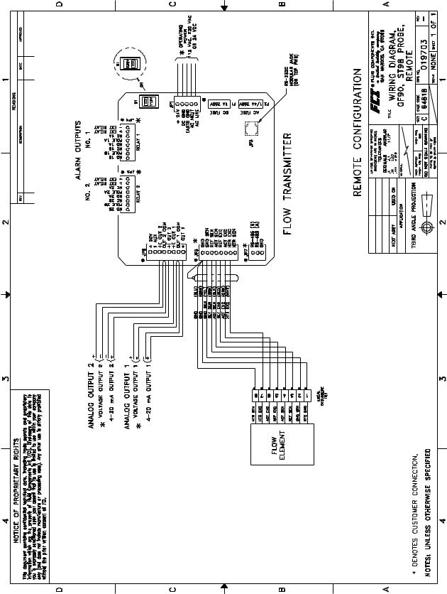
Remote Transmitter
Feed the flow element cable and the two voltage/current output cables through the left access port in the remote enclosure. Similarly, feed the AC power line and the two relay cables through the right port. This separates the I/O signal and low voltage DC lines from the high voltage AC and relay lines. See wiring diagram, Figure 8 for the flow element wiring to JP3. Customer connections needing to be made are to JP4 and JP5 (relay logic), and also to JP6 (current or voltage).
Doc. No. 06EN003229 Rev. H |
17 |
GF Series Flowmeter Models GF90/GF92 |

FLUID COMPONENTS INTERNATIONAL LLC |
|
http://www.fluidcomponents.com |
|
|
|
|
|
|
|
|
|
|
|
|
|
Figure 8. GF90 or GF92 Wiring Diagram
GF Series Flowmeter Models GF90/GF92 |
18 |
Doc. No. 06EN003229 Rev. H |
FLUID COMPONENTS INTERNATIONAL LLC |
http://www.fluidcomponents.com |
||
|
|
|
|
|
|
|
|
Figure 52. ST98 or ST98L Remote Wiring Diagram
Doc. No. 06EN003229 Rev. H |
19 |
GF Series Flowmeter Models GF90/GF92 |
FLUID COMPONENTS INTERNATIONAL LLC |
http://www.fluidcomponents.com |
|||
Customer |
Jacks JP3 (top circuit board), JP4, JP5, JP6 and JP7 are for customer use and are described in Table 3. |
|||
Wiring |
|
Table 3. Customer Wiring |
||
|
|
|||
|
|
|
|
|
|
|
JACK / NOMENCLATURE |
DESCRIPTION |
|
|
|
JP3 (Top Circuit Board) |
Used in conjunction with equipment compatible |
|
|
|
with an RS 232 (EIA-232) serial port. See |
|
|
|
|
RS-232 (EIA-232) Serial Port |
|
|
|
|
|
Chapter 4 for more details. |
|
|
|
|
Factory pre-programmable relay contacts. Two |
|
|
|
JP4 |
normally open and normally closed contacts are |
|
|
|
Relay Output 1 |
available (double pole, single throw relay) per |
|
|
|
and |
jack. External relays can be connected to the |
|
|
|
JP5 |
+EXT and -EXT pins in each jack. |
|
|
|
Relay Output 2 |
Recommended relays are 18 Vdc, 0. |
|
|
|
|
There are two factory pre-programmable signals |
|
|
|
JP6 |
which are voltage and/or current. The 1AUX and |
|
|
|
+20 V pin is a customer option for the use as a |
|
|
|
|
Analog Output |
|
|
|
|
dynamic correction factor. See Chapter 4 for |
|
|
|
|
|
|
|
|
|
|
more information |
|
|
|
JP7 |
Used in conjunction with equipment compatible |
|
|
|
RS485 (EIA-485) Serial Port |
with an RS 485 (EIA-485) serial port. |
|
Serial Communication Option
(Hyper Terminal Hook Up)
The RJ-12 (P3) connector on the top circuit board ( near the right side of the key pad) provides RS-232 communication with the user. An FC88 Communicator can be plugged in for periodic re-configuration and/or diagnostics, or personal computer can be plugged in instead of the FC88 Communicator. This connection is a RJ-12 communication (phone) jack. Figure 7 shows the connection between the serial port and a host device. Figure 56 shows the wiring of the DB-9 connector.
|
|
|
Serial Port |
RJ-12 Pin |
IBM PC |
|
|
||||||||
|
RJ-12 Phone Jack |
Description |
DB-9 Connector |
||||||||||||
6 |
|
|
|
|
|
|
|
+5V |
|
|
|
|
|
|
|
|
|
|
|
|
|
|
1 |
|
|
|
|
|
|||
5 |
|
|
|
|
|
|
|
NC |
2 |
|
|
DCD |
1 |
Data Carrier Detect |
|
4 |
|
|
|
|
|
|
|
DTR |
3 |
|
|
DTR |
4 |
Data Terminal Ready |
|
|
|
|
|
|
|
|
|
|
|||||||
3 |
|
|
|
|
|
|
|
TXD |
4 |
|
|
TXD |
3 |
Transmit Data |
|
|
|
|
|
|
|
|
|
|
|||||||
2 |
|
|
|
|
|
|
|
RXD |
5 |
|
|
RXD |
2 |
Receive Data |
|
|
|
|
|
|
|
|
|
|
|||||||
1 |
|
|
|
|
|
|
|
GND |
6 |
|
|
GND |
5 |
Ground |
|
|
|
|
|
|
|
|
|
|
|||||||
|
|
|
|
|
|
|
|
|
|
|
|
|
JUMPER |
7 |
Jumper |
|
|
|
|
|
|
|
|
|
|
|
|
|
|||
|
|
|
|
|
|
|
|
|
|
|
|
|
JUMPER |
8 |
Jumper |
|
|
|
|
|
|
|
|
|
|
|
|
|
|||
|
|
|
|
|
|
|
|
|
|
|
|
|
|
||
|
|
|
|
|
|
|
|
|
|
RJ-12 Pin |
IBM PC |
|
|
||
|
|
|
|
|
|
|
|
|
|
Description |
DB-25 Connector |
||||
|
|
|
|
|
|
|
|
+5V |
|
|
|
|
JUMPER |
4 |
Jumper |
|
|
|
|
|
|
|
|
|
|
|
|
||||
|
|
|
|
|
|
|
|
|
1 |
|
|
JUMPER |
5 |
Jumper |
|
|
|
|
|
|
|
|
|
|
|
|
|||||
|
|
|
|
|
|
|
|
NC |
|
2 |
|
|
DCD |
8 |
Data Carrier Detect |
|
|
|
|
|
|
|
|
DTR |
|
3 |
|
|
DTR |
20 Data Terminal Ready |
|
|
|
|
|
|
|
|
|
TXD |
|
4 |
|
|
TXD |
2 |
Transmit Data |
|
|
|
|
|
|
|
|
RXD |
|
5 |
|
|
RXD |
3 |
Receive Data |
|
|
|
|
|
|
|
|
GND |
|
6 |
|
|
GND |
7 |
Ground |
|
|
|
|
|
|
|
|
|
|
|
|
|
|
|
C00251-1 |
|
|
|
|
|
|
|
|
|
|
|
|
|
|
|
|
Figure 7. Wiring Diagram, DB-9 and DB-25 PC Connectors
GF Series Flowmeter Models GF90/GF92 |
20 |
Doc. No. 06EN003229 Rev. H |

FLUID COMPONENTS INTERNATIONAL LLC |
http://www.fluidcomponents.com |
||
|
|
|
|
|
|
|
|
Figure 56. Wiring of DB-9 Connector
FCI recommends using the PC Interface Kit P/N: 014108-02 to connect the flow transmitter to a personal computer. The kit includes operation instructions and an adaptor for the RJ-12 to serial connection. Connect one end of the interface kit to the RJ-12 port and the other end to a DB pin connector. Plug the connector into the COM1 or COM2 port in the back of the computer terminal.
See instructions on how to use the serial communications in the next chapter.
HART |
Use the following steps to install the Hart Option for GF90/GF92: |
||
Option |
1. |
All the FCI transmitters that incorporate the HART protocol are set at the factory to polling address “0”. |
|
Installation |
|||
|
|
Users should reset the polling address to match the needs of their network. |
|
|
2. |
At polling address “0”, the GF90/GF92 outputs a current of 4-20 mA; at any other polling address, the |
|
|
|
GF90/GF92 outputs a fixed 4 mA current; in compliance with the HART standard. A digital signal is |
|
|
|
provided with all polling addresses. |
|
|
3. |
If the GF90/GF92 is going to be used as a HART network transmitter, the polling address needs to be |
|
|
|
changed to other than “0”. |
|
|
4. |
When the GF90/GF92 is connected in a HART Network, the instrument is configured for an external |
|
|
|
current source. The polling address must be changed to other than “0”. The power supply feeding the |
|
|
|
network must provide sufficient current to support the instruments in the network. |
|
|
|
|
|
|
|
|
|
Figure 9. Hart Module
WiringtheHartInstrument
INPUT POWER - Follow the GF90/GF92 manual to connect power.
OUTPUT SIGNAL - The GF90/GF92 analog outputs are factory connected to the hart modules. The two diagrams below shows recommended methods of connecting the HART modules to the customer’s system.
Doc. No. 06EN003229 Rev. H |
21 |
GF Series Flowmeter Models GF90/GF92 |

FLUID COMPONENTS INTERNATIONAL LLC |
http://www.fluidcomponents.com |
|
Ω |
|
Ω |
Ω |
|
Figure 10. Hart Module Wiring Option 1
Ω |
Ω |
Ω |
Ω |
Figure 11. Hart Module Wiring Option 2
GF Series Flowmeter Models GF90/GF92 |
22 |
Doc. No. 06EN003229 Rev. H |

FLUID COMPONENTS INTERNATIONAL LLC |
http://www.fluidcomponents.com |
MAIN MENU
1DEVICE SETUP
2VOLT (Displays actual process value, i.e. flow)
3LRV (Displays configured lower range value)
4URV (Displays configured upper range value)
5I OUT (Displays actual output current in mA)
6% RANGE (Shows output current in % output span)
7DATALOGGER
GF90/GF92 HART
MENU TREE
|
1 DEVICE SETUP MENU |
1 INPUT SETUP |
|
1 Signal Condition |
|||||||
|
1 |
SIGNAL CONDITION |
|
|
1 |
SENSOR (mV Hi) |
|
||||
|
1 |
INPUT SETUP |
|
|
2 |
SENSOR TYPE (Enter Sensor type |
|
|
2 |
USL (Upper sense level |
|
|
2 |
OUTPUT SETUP |
|
|
|
i.e. RTD, T/C, mV, Ohm, Pot) |
|
|
|
i.e. 1000 mV) |
|
|
3 |
DEVICE INFO. |
|
|
3 |
LRV (Enter lower range value) |
|
|
3 |
LSL (Lower sense level |
|
|
4 |
DIAG/SERVICE |
|
|
4 |
URV (Enter upper range value) |
|
|
|
i.e. 0 mV) |
|
|
|
|
|
|
5 |
DAMP (Enter damping value) |
|
|
4 |
MIN SPAN (20 mV) |
|
|
|
|
|
|
|
|
|
|
|
|
|
|
7 DATALOGGER MENU |
2 OUTPUT SETUP* |
||||||||||||||||||
|
1 MAX. VALUE (Displays highest process |
|
|
|
|
1 |
UNDER LIM (Enter the output current for measurements LOWER |
|
|
|||||||||||
|
|
|
value since reset) |
|
|
|
|
|
|
|
|
|
than configured range, i.e. if temp. falls below 0°C) |
|
||||||
|
2 |
MIN. VALUE (Displays lowest process |
|
|
|
|
2 |
OVER LIM (Enter the output current for measurements HIGHER |
|
|||||||||||
|
3 |
|
value since reset) |
|
|
|
|
|
|
|
|
|
than configured range, i.e. if temp. goes above 100°C) |
|
||||||
|
RESET MIN/MAX (Reset the memory |
|
|
|
|
3 |
|
|
2.1 |
|
|
|
|
|
||||||
|
|
|
holding min/max data) |
|
|
|
|
SENS ERR (Enter the output current in case sensor fails. |
|
|||||||||||
|
|
|
|
|
|
|
|
|
|
|
|
|
|
|
|
|
|
|
|
|
|
|
|
|
|
|
|
|
*This is a sub menu, where the out-of-range and |
||||||||||||
|
|
3 DEVICE INFO |
|
sensor-burn-out can be entered. |
||||||||||||||||
|
|
|
|
|
|
11 HART Output |
||||||||||||||
|
|
1 |
DISTRIBUTOR (Displays name Kamstrup) |
|
|
|
|
|||||||||||||
|
|
|
|
|
|
1 |
POLL ADR (Enter the polling adr. for the FlexTop |
|
|
|
||||||||||
|
|
2 |
MODEL (Displays name FlexTop HRT) |
|
|
|
|
|
|
|
HRT. Observe that poll adr = 0 |
|
|
|
||||||
|
|
3 |
DEV ID (Displays device serial number) |
|
|
|
|
|
|
|
|
|
|
|||||||
|
|
|
|
|
|
|
|
|
automatically sets the FlexTop HRT in |
|
|
|
||||||||
|
|
4 |
TAG (Enter tag number (identify FlexTop HRT)) |
|
|
|
|
|
|
|
|
|
|
|||||||
|
|
|
|
|
|
|
|
|
analog mode, resulting in a mixed-signal |
|
|
|
||||||||
|
|
5 |
DATE (Enter date of choice, i.e. date of event) |
|
|
|
|
|
|
|
|
|
|
|||||||
|
|
|
|
|
|
|
|
|
setup. If intent is to connect several |
|
|
|
||||||||
|
|
6 |
WRITE PROT. (Displays write protect status, NONE) |
|
|
|
|
|
|
|
|
|||||||||
|
|
|
|
|
|
|
FlexTop's in Multi-drop mode, poll |
|
|
|
||||||||||
|
|
7 |
DESCRIPTOR (Enter description, ie a location code) |
|
|
|
|
|
|
|
|
|||||||||
|
|
|
|
|
|
|
addresses 1 to 15 must be used. |
|
|
|
||||||||||
|
|
8 |
MESSAGE (Enter message, i.e. a warning) |
|
|
|
|
|
|
|
|
|
|
|||||||
|
|
|
|
|
|
2 |
NUM PREAMS (Displays number of preamble |
|
|
|
||||||||||
|
|
9 |
FINAL ASMBLY NUM (Enter 8 digits, i.e. ref # |
|
|
|
|
|
|
|
||||||||||
|
|
|
|
|
|
|
|
|
characters sent by master to ensure |
|
|
|
||||||||
|
|
|
identifying sensor and transmitter during a |
|
|
|
|
|
|
|
|
|
|
|||||||
|
|
|
|
|
|
|
|
|
|
sync with the slave device. |
|
|
|
|||||||
|
|
|
calibration session) |
|
|
|
|
|
|
|
|
|
|
|||||||
|
|
|
|
|
|
|
|
|
|
|
|
|
|
|
|
|||||
|
|
10 |
REVISION #'s (Displays the rev #'s of command set |
|
|
|
|
|
|
|
|
|
|
|
||||||
|
|
|
|
|
1 Loop Test |
|||||||||||||||
|
|
|
(5), the FlexTop HRT(2) and the DD software (3)) |
|
|
|
||||||||||||||
|
|
11 |
HART OUTPUT4.1 |
|
|
|
|
|
|
|
|
|
|
|
|
|
||||
|
|
|
|
|
|
|
1 |
|
4 mA FIXED OUTPUT |
|
|
|
|
|
||||||
|
|
|
|
|
|
|
|
|
|
|
|
|
2 |
|
20 mA FIXED OUTPUT |
|
|
|
|
|
|
|
|
|
|
|
|
|
|
|
|
|
|
3 |
|
OTHER (Inter value of fixed current output) |
|
|
|
|
|
|
|
|
|
|
|
|
|
|
|
|
|
|
4 |
|
END (Leave the menu) |
|
|
|
|
|
|
|
4 DIAG/SERVICE** |
|
|
|
|
|
|
|
|
|
|
|
|
|
|||||
|
|
|
|
|
|
|
|
|
|
|
|
|
|
|
||||||
|
|
|
|
|
|
|
3 Sensor Trim |
|||||||||||||
|
|
1 |
LOOP TEST (Enter/Change loop |
|
|
|
|
|
|
|
|
|
||||||||
|
|
|
|
|
|
|
|
|
|
|
|
1 |
FACTORY TRIM (Offset and gain values are |
|
|
|||||
|
|
|
current to fixed value) |
|
|
|
|
|
|
|
|
|
|
reset to factory settings) |
|
|
||||
|
|
2 |
D/A TRIM (Connect a reference meter |
|
|
|
|
|
|
|
|
|
|
|
|
|
||||
|
|
|
|
|
|
|
|
|
|
|
2 |
ONE POINT TRIM (Enter reference temp. value for a |
|
|
||||||
|
|
|
(5 digit). Compensate for |
|
|
|
|
|
|
|
|
|
|
|
|
|||||
|
|
|
|
|
|
|
|
|
|
|
|
|
|
non-calibratedsensor. Displays measured |
|
|
||||
|
|
|
the inaccuracy in output |
|
|
|
|
|
|
|
|
|
|
|
|
|
||||
|
|
|
|
|
|
|
|
|
|
|
|
|
temperature. If ref temperatures are different, |
|
|
|||||
|
|
|
D/A converter) |
|
|
|
|
|
|
|
|
|
|
enter this value. |
|
|
||||
|
|
3 |
SENSOR TRIM |
|
|
|
|
|
|
|
|
|
3 |
TWO POINT TRIM(Enter 2 reference temperature |
|
|
||||
|
|
|
|
|
|
|
|
|
|
|
|
|
|
|
values. Displays actual measured temp. If |
|
|
|||
|
|
|
|
|
|
|
|
|
|
|
|
|
|
|
reference temps are different, enter the |
|
|
|||
|
|
|
|
|
|
|
|
|
|
|
||||||||||
|
|
**WARNING: |
|
|
|
|
|
|
|
values. The gain is #1, the function curve will |
|
|
||||||||
|
|
|
|
|
|
|
|
|
|
|
||||||||||
|
|
|
|
|
|
|
|
|
change the slope and not start in the zero |
|
|
|||||||||
|
|
To enter this menu, remove the loop from automatic |
|
|
|
|
|
|
||||||||||||
|
|
|
|
|
|
point) |
|
|
||||||||||||
|
|
control. All trim adjustments can be carried out from |
|
|
|
|
|
|
||||||||||||
|
|
|
|
|
4 |
VOLT. (Not used by FCI) |
|
|
||||||||||||
|
|
the configurator only - not from the FlexProgrammer. |
|
|
|
|
|
|||||||||||||
|
|
|
|
|
5 |
S. OFF. (This is the differencebetweenthe measured |
|
|
||||||||||||
|
|
|
|
|
|
|
|
|
|
|
|
|
|
6 |
and the reference value. Enter this value) |
|
|
|||
|
|
|
|
|
|
|
|
|
|
|
|
|
|
S. GAIN (Enter this value. This adjustment |
|
|
||||
|
|
|
|
|
|
|
|
|
|
|
|
|
|
|
corresponds to the 2-point trim. However |
|
|
|||
|
|
|
|
|
|
|
|
|
|
|
|
|
|
|
the function curve will start in the zero point. |
|
|
|||
|
|
|
|
|
|
|
|
|
|
|
|
|
|
|
|
|
|
|
|
|
|
|
|
|
|
|
|
|
|
|
|
|
|
|
|
|
|
|
|
|
|
Figure 12. HART Module Menu Tree
Doc. No. 06EN003229 Rev. H |
23 |
GF Series Flowmeter Models GF90/GF92 |

FLUID COMPONENTS INTERNATIONAL LLC |
http://www.fluidcomponents.com |
Foundation
Field Bus
Foundation Fieldbus access to the GF90/GF92 signals is accomplished through the SMAR IF302 Current to Fieldbus Converter. Two GF90/GF92 parameters are available through the IF302; Process Flow in Channel 1 and Process Temperature in Channel 2.
The SMAR IF302 contains 18 functional blocks, and the GF90/GF92 flow and temperature signals are presented at the output of the corresponding “Analog Input” blocks in mA.
For complete details on the IF302 please go to the SMAR web site at www.smar.com and register to recieve the “Operation and Maintenance Instruction Manual”.
Installation GF90/GF92 and IF302
Connect the GF90/GF92 Flow current output to the Channel 1 input of the IF302, and then connect the GF90/GF92 Temperature current output to Channel 2 of the IF302.
Figure 13. Foundation Field Bus Module Wiring Diagram
GF Series Flowmeter Models GF90/GF92 |
24 |
Doc. No. 06EN003229 Rev. H |

FLUID COMPONENTS INTERNATIONAL LLC |
http://www.fluidcomponents.com |
FactorySetupofIF302
FCI sets the tags on the AI blocks that contain the signal connection to the Flow channel and the Temperature channel identifying them as shown below.
Other configuration and tag definitions are left to the system integrator.
Isolated
Output
Option
and 4-20 mA Adjustment
An isolated 4 to 20 milliampere (mA) output is an available option. The isolated output is available by connecting a loop powered isolator module to the transmitter output. The modules have their own set of output terminals which provide an isolated 4 to 20 mA output equal to the non-isolated instrument output. This one-to-one current isolation is used to prevent instrumentation ground loops. See
Figure 14 for the wiring diagram to install the isolated output module.
Use of the isolator module will add a small signal conversion error to the instrument output and limit the output load to 350 ohms.
Doc. No. 06EN003229 Rev. H |
25 |
GF Series Flowmeter Models GF90/GF92 |

FLUID COMPONENTS INTERNATIONAL LLC |
http://www.fluidcomponents.com |
|
LT81 Series |
NOTE: Follow the wiring diagrams in Appendix A to reconnect the existing flow element to the |
|
Upgrade |
replacement GF series flow transmitter, and to install a jumper on the flow element terminal |
|
Information |
board if applicable. |
|
|
|
|
The LT analog series flowmeters can be fully upgraded to the GF series flowmeters by replacing the LT series transmitter with a properly calibrated GF series transmitter. The flow elements are the same except for wiring differences at the flow element. The analog outputs also change locations. Jumper wire is added from terminal 2 to terminal 4 of the flow element head terminal block. New connectors will need to be installed on the transmitter for power, relays, flow element and analog output.
Apply |
The input power should not be turned on until the installation has been completed with all connections |
||||||
Power |
verified, power and signal connection board assembly screwed down and the instrument ready to |
||||||
|
operate. Be sure any external circuit breakers are on. |
||||||
|
|
|
|
|
|
|
|
|
|
|
|
|
|
|
|
|
|
|
|
|
|
|
|
|
|
|
|
|
|
|
|
|
|
|
|
|
|
|
|
|
|
|
|
|
|
|
|
Figure 14. Isolated Output Option Wiring Diagram
GF Series Flowmeter Models GF90/GF92 |
26 |
Doc. No. 06EN003229 Rev. H |
Loading...