

Page 1

CHAPTER 3 - OPERATION FLUID COMPONENTS INTL
3. Operation
Alert:
Introduction
The instrument has been configured and calibrated to customer specifications. Each instrument contains distinct
operating limits and units of measurement. This chapter will show how to determine and manipulate the
configuration of the instrument.
Start Up
Verify the wiring before applying power. Verify the correct power connections have been made to the flow
transmitter. If the instrument does not have a display, plug in an FC88 Hand Held Communication unit or other
compatible communication device into P1 of the customer connection board.
1. Apply power.
2. When operating power is applied to the instrument the following messages will be displayed:
The flow transmitter contains electrostatic discharge (ESD) sensitive devices. Use standard ESD
precautions when handling the flow transmitter. See Chapter 2, Installation for ESD details.
"FCI ST98",
"Initialization!",
"Heater On!"
3. Wait 5 minutes for the instrument to warm-up and stabilize.
4. The instrument automatically enters the flow metering mode. The instrument's display (if present), and /or
the FC88 display will show the normal operation.
Note: If the FC88 does not display the monitored results properly, press [P] to re-configure the FC88 to the
operation of the ST98.
The flow meter displays an output signal that is representative of the calculated current process media flow.
If the display does not appear, or is out-of-range for the expected values, turn the power off and proceed to
Chapter 5 -Troubleshooting.
Using an FC88 Communicator
An FC88 is a hand held communicator that is plugged into the flow meter which controls the various functions of
the ST98. Plug in the FC88 to P1 of the customer connection board. See Figure 2-4 for details.
This instrument is convenient, compact, and obtains its operating power from the flow transmitter. It provides a
keypad for operator input and a display for system output.
Menu Control and Organization
Most entries require at least two key strokes; a letter and the [ENTER] key, or one or more numbers and the
[ENTER] key. All user entries begin at the Input Mode?< prompt except when the instrument is in the Main
Function Mode (just press the letter and [ENTER] to make an entry).
Doc. No. 06EN003291 Rev. A 3 - 1 Model ST98 Flow Meter
Page 2
FLUID COMPONENTS INTL CHAPTER 3 - OPERATION
A user entry is indicated by brackets [ ] being placed around the entry. Y/N refers to Yes (Y), save or change
parameter or No (N) do not save or change parameter unless otherwise specified.
Backspaces are made using the backspace [BKSP] key.
Some entries are case sensitive between numbers and letters. Be sure the SHIFT key is pressed to indicate the
correct case. A square after the prompt caret indicates the FC88 is in lower case. A slightly raised rectangle in the
same spot indicates the FC88 is in the upper case.
It is recommended that the FC88 be plugged into the instrument before power is applied. If the FC88 is plugged in
while the instrument power is on and the FC88 does not respond, press [ENTER], if there is no response press [P],
if there is still no response Press [N].
Note: Some entries require a pass code (942) to continue programming the instrument. The instrument will
prompt the user when this is necessary. Do not change any parameters that require this code unless there
is an absolute understanding of the instrument's operation. Incorrect changes can cause an inaccurate or
a non-operational instrument. The figures in the "Delta "R" Table would need to be re-input.
The user can not exit some routines unless all entries are completed or the power is recycled.
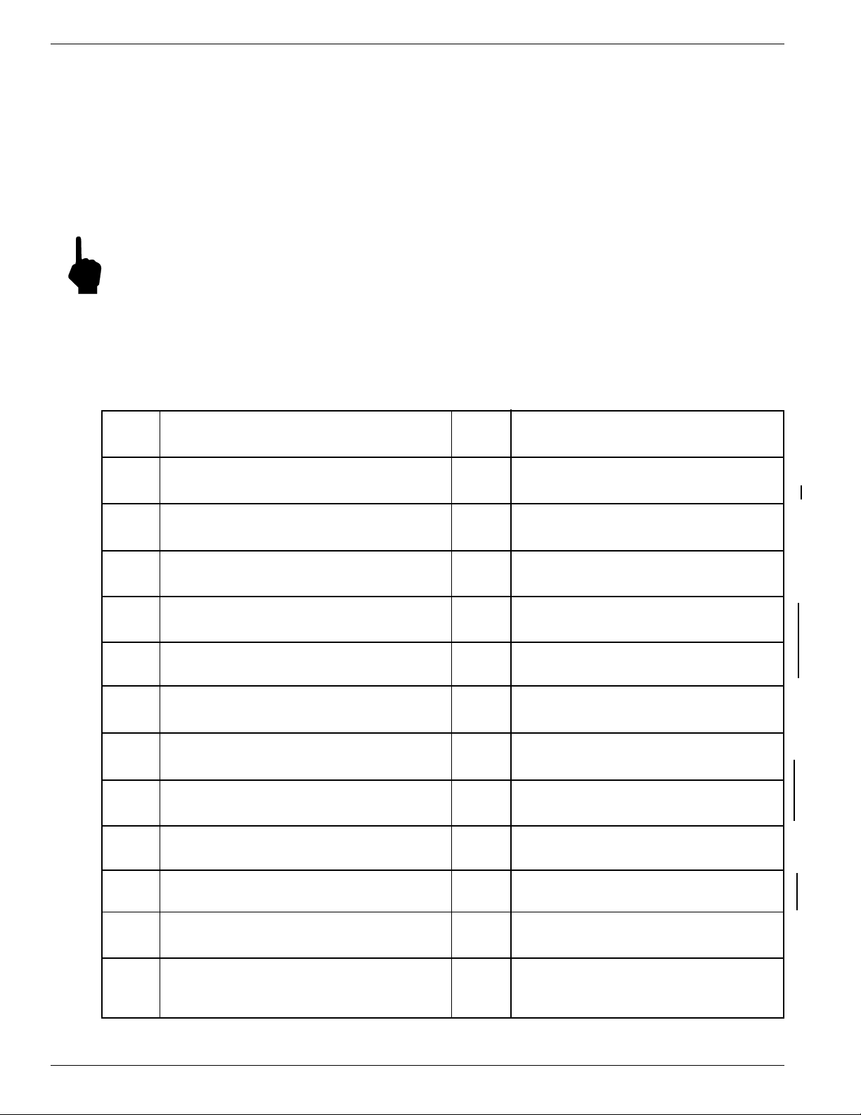
The top level of the menu is shown below. Press the large letter in the Figure 3-1 to activate a command.
Analog Input
A
Rotate through the 8 analog input channels
Sensor Balance
B
Balance or rebalance Flow Element
Calibrate Display
C
Display A/D Delta-R and Ref-R data values
Diagnostic
D
Check out functional conditions of the unit
Sensor Current Select
E
Displays 2.0 mA - 1k ohm
K-Factor
F
K-Factor entered by user.
EEPROM PW = available when needed
G
EEPROM byte locations - read/ write.
Heater
H
Toggle heater circuit - OFF/ ON.
Output Current Adjust
I
Manually set output: 4-20 mA, display output load
Software Reset
N
O
P
Re-initialize instrument without removing power
Select Sensor Heater Current
HIGH (90 mA) or LOW (75 mA)
Re-configure FC88 Unit
Reset the FC88 hand held to ST98 format
Undefined
Q
Delta-R, Ref-R, CB Temp, -8/+20 V
R
Display Delta-R, Ref-R resistor values, etc.
Save/Restore USER Save and FACTORY
S
T
U
V
Calibration data saved and restored
Normal Operating Mode
Display flow rate, temperature, totalized flow
Display Total Flow Time
Total time (min) in T mode since last reset
NAMUR Output Fault Indicator
NAMUR flag, select fault indicator
Serial/Customer Numbers
J
Enter Serial No. and Customer Order No.
Constants Setup
K
Setup curve fit, TC parameters, and other data
Calibrate Outputs
L
Outputs - Heater Current, 4 mA, 20 mA levels.
Min/Max A/D Limits
M
Set minimum and maximum A/D limits
Figure 3-1. Menu Selections Chart
Model ST98 Flow Meter 3 - 2 Doc. No. 06EN003291 Rev. A
W
X
Y
Z
Totalizer Mode
Enable totalized flow w/wo temperature
NAMUR Output Fault Indicator
Toggle NAMUR flag(on/off) select fault indicator
Undefined
Flow Units Select
Select flow units (3 English , 3 Metric)
Page 3
CHAPTER 3 - OPERATION FLUID COMPONENTS INTL
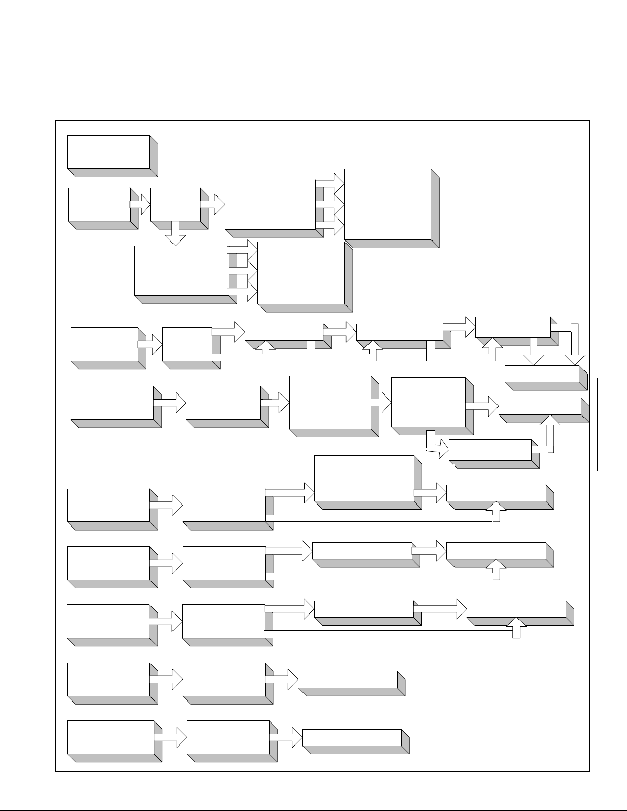
Quick Start Menu (Abbreviated)
The following menu shows how to use the most frequently accessed functions of the instrument. See Figure 3-1 for
the complete menu. A complete menu explanation follows this Table.
Table 3-1. Quick Start Menu (Abbreviated Menu, See Chapter 3 For Full Details)
NORMAL
OPERATING
[T]
[Z]
MODE
FLOW
UNITS
SELECT
ENGLISH
OR
METRIC
M
M SMPS(VELOCITY)
N NCMH(VOLUME)
K KG/HR (MASS)
ST98 ABBREVIATED MENU
SEE THE LAST
E
F SFPS(VELOCITY)
C SCF M(VOL UME)
L LBS/HR (MASS)
M
SEE THE LAST
N
- OPERATION -
K
PAGES OF
CHAPTER 3
FOR DETAILS
F
C
- OPERATION -
L
PAGES OF
CHAPTER 3
FOR DETAILS
[W]
[X]
[V]
[U]
[F]
TOTALIZE
MODE
NAMUR
FAULT
INDICATOR
OUTPUT
MODE
SELECT
DISPLAY
OF TOTAL
FLOW T IME
K-FACTOR
ON/OFF
TOGGLE
INPUT
PASSCODE
OUTPUT: XXX
CHANGE IT?<
RESET IT?<
K.F. = 1.0000000
CHANGE IT?<
YES
NO
RESET TO TALIZER
NAMUR FL AG IS
OFF, TURN ON
ON, TURN OFF
YES
NO
YES
NO
YES
NO
YES
NO
OR
RESET AT POWER UP
IOUT:22mA
CHANGE IT?
IOUT: 3.5mA
CHANGE IT?
0: 4-20
1: 0-5
2:0-10
ENTER#
TIME = 0.0000000 EXITS COMMAND
INPUT K.F. #
YES
NO
YES
TEMP DISPLAY
ON/OFF TOGGLE
NO
0=22.0mA
1=3.5mA
EXITS COMMAND
EXITS COMMAND
YES
NO
EXITS COMMAND
EXITS COMMAND
REINITIALIZES
WITHOUT
POWER DOW N
EXITS COMMAND
PRESS [ENTER] AFTER
[N]
SOFTWARE
RESET
EACH MENU SELECTION
RE-CONFIGURE
[P]
Doc. No. 06EN003291 Rev. A 3 - 3 Model ST98 Flow Meter
FC88
RESETS FC88
TO USE W ITH
ST98
EXITS COMMAND
TO ACTIVATE COMMAND
Page 4

FLUID COMPONENTS INTL CHAPTER 3 - OPERATION
Detailed Menu Description
This section describes the menu of commands. The commands are listed in alphabetical order with no order of
priority.
Note: Menu Commands are initiated by pressing the appropriate character key followed by the ENTER key.
COMMAND:
A. Analog Input
Summary:
Permits the user to display the Analog To Digital (A/D number) of the eight analog input channels. The A/D
number has a span of 0-4096 counts which is proportional to 0-4 V at the input to the A/D converter. Channels 0
through 3 receive a signal voltage that has been amplified by a factor of nine. Channels 4 through 7 are not
amplified.
These numbers can help a technician determine the cause of a problem with the installation or operation of the
flowmeter. FCI recommends making a note of these readings.
Description:
When command [A] [ENTER] is pressed, the instrument will respond by displaying the signal for Channel 0.
Continually pressing the [ENTER] key displays the rest of the channels and will rotate back to channel 0 following
the Channel 7 selection. This command is useful in trouble shooting incorrectly wired instruments and open flow
elements. This is a view only selection, the user has no other input commands.
Channel Signal Name
Number
0 ACT_SEN - REF_SEN Raw Delta-R x Gain (»9) Raw flow signal with a gain of 9, used for high flow rate.
1 -8 Volt Supply Monitor Check for -8 Volt Supply limits.
2 Sensed mA Output Load Monitor Used in calculating the output load in ohms.
3 +20 Volt Supply Monitor Check for +20 Volt Supply limits.
4 ACT_SEN - REF_SEN Raw Delta-R Raw flow signal with gain of 1, used for lower flow rate.
5 HTR_SEN - GND Sensed Heater Voltage Check the condition of the heater.
6 Circuit Board Temperature Monitor Check for Circuit Board Temperature limits.
7 REF_SEN - GND_SEN Sensed Ref-R Used to measure the reference sensor for process temp.
Purpose and Symptom
Example:
Pressing [A] [Enter] displays “Ch(0): xxxx”
[Enter] displays “Ch(1): xxxx”
[Enter] displays “Ch(2): xxxx”
[Enter] displays “Ch(3): xxxx”
[Enter] displays “Ch(4): xxxx”
[Enter] displays “Ch(5): xxxx”
[Enter] displays “Ch(6): xxxx”
[Enter] displays “Ch(7): xxxx”
[Enter] displays “Ch(0): xxxx”
Note:
Model ST98 Flow Meter 3 - 4 Doc. No. 06EN003291 Rev. A
Pressing [Q] [ENTER] at any time will exit this menu item and display “Input mode ?<”.
Page 5

CHAPTER 3 - OPERATION FLUID COMPONENTS INTL
COMMAND:
B. Sensor Balance
Summary:
Permits the instrument's flow element to be balanced or rebalanced. A passcode must be entered. This function
has already been performed at the factory. This function should only be performed if there is a new flow element
installed or a re-calibration is necessary.
Description:
For the instrument to function properly, the flow element and electronics need to be balanced. Balancing means
that at the same temperature, the RTD's in the flow element should be at the same resistance. Due to physical
differences in the RTD's, the current needs to be adjusted for one of the RTD's so that they will both have the same
voltage. The differential should be as close to zero as possible. A passcode is necessary to enable this command.
The instrument will either balance itself or it can be done manually.
Note:
Use M (Manual) command when the circuit board or flow element has been replaced and where the
balance value representing the digitized current used for balancing has been written down.
If the Heater was ON prior to sensor balancing, be sure to turn the Heater back ON after the RTD's have
been balanced.
Example:
Pressing [B] [ENTER] will display “Enter Code #”
Press in the passcode [ENTER]. “Enter temp. #” will be displayed.
After the temperature is entered, “Auto or Manual?” and “Enter A or M<” are displayed.
Pressing [A] [ENTER] will display “xxx xxxx Balancing”. Then “Balanced!” will appear on line 1 and
“Saved! xxx” will appear on line 2.
If [M] [ENTER] is pressed instead of [A] [ENTER], the prompt “Enter Balance #” will be displayed. Once
the balance value [xxx] is entered, the balanced value entered appears on line 1 and “Saved!” is displayed on
line 2. After a couple of seconds "Saved! xxx" will be displayed on line 1 and "Input mode?<" will be
displayed on line 2. (Typical Balance values are; 234-237. Factory Balance # is on in the Delta R Table.)
COMMAND:
C. Calibrate Display
Summary:
Displays A/D Delta-R and Ref-R. Data values are useful for calibration. The instrument is calibrated at the
factory. This function does not need to be performed unless the instrument has been repaired or needs to be recalibrated.
Description:
The flow element RTD's need to be interpreted by the electronics as a function of flow-rate. This is done by
recording the raw signal A/D values at certain flow points and then curve-fitting the points using an equation to
linearize the output at the calibrated flow-rate. This command makes it possible to view both the raw A/D Delta-R
value, which is the difference between the Active and Reference RTD, and the Ref-R value, which is for the
Reference RTD. This is a view only selection, the user has no other input commands.
Example:
Pressing [C] [ENTER] will display “d= xxxx R= xxxx”. The display is updated continuously.
Note:
Doc. No. 06EN003291 Rev. A 3 - 5 Model ST98 Flow Meter
Pressing [ENTER] at any time will exit this menu and display "Input mode?<"
Page 6

FLUID COMPONENTS INTL CHAPTER 3 - OPERATION
COMMAND:
D. Diagnostic
Summary:
Permits the user to check the functional conditions of the instrument.
Description:
This mode displays all of the critical and peripheral variables that are stored in RAM (operational data area). By
pressing the [Enter] or the [U]/[+] key, the data is displayed in an ascending order. By pressing the [P]/[-] key,
data is displayed in a descending order. Pressing the [Q] key at any time will exit the Diagnostics menu. The
ST98 functional data in RAM is saved in the USER area of the Non-Volatile Memory (NVM). The user has the
option to save user data to the USER Save area of NVM at any time. At completion of the FCI calibration, the
data was saved to the FACTORY area of NVM. Each of these data areas may be viewed by the user (Refer to
Menu item ‘S’ for more detail on saving and restoring the NVM data areas).
Example:
At BOOTUP or RESET, the following is displayed: “Initialization!”, with “FCI ST98” flashing, followed by
“Heat On!”.
Pressing D [Enter] will display “USER Displayed” followed by “Change it ? <”. If ‘N’ or [Enter] is pressed,
USER data is displayed. If [Y] is pressed, “1=USER Save” followed by “2=FACTORY” is displayed. Pressing a
‘1’ or ‘2’ will cause the respective NVM data to be displayed: “Version X.XX” (also displayed at BOOTUP or
RESET).
The rest of the values will be displayed by pressing the [Enter] key after each value.
“Serial Number “,
“xxxxxxxxx”,
“Customer Number”,
“xxxxxxxxx”,
“Curve fit: x”,
NOTE: Curve fit = 0, is for “single poly fit”; Curve fit = 2, is for “two poly fit”
The following values are typical:
If Curve fit = 2 was chosen, the instrument will display “two poly fit” on line 1 and “Brkpt: 1432” on line 2.
“Poly Segment 1” are “C1 = 79.3892”, “C2 = -2.362808”, “C3 = 28.23582”,
“C4 = -104.3832”, “C5 = 1.070937”.
“Poly Segment 2” are “C1 = 69.04044”, “C2 = -8.793838, “C3 = 206.3617”, “C4 = -1544.267”, “C5 =
39.06467”.
“Balance: 237”, “Outz: 432”, “Outf: 2144”, “Heater_I: 3070”, “Factor: 1.00000”, “Eu: 70 (F)”, “Tot: 0”,
“Tottemp: 0”, “Tflow: 0.000000”, “Rollover: 1E6”, “Roll cnt: 0”, “Outmode: 0”, “Max A/D: 6500”,
“Min A/D: 200”, “Kfactor: 1.0000”, “Zero: 0.0000”, “Sensor: 0”, “Tslp: 0.23759989”, “Refr: 1800.00”,
“Caltemp: 70.00”, “Toff: -351”, “Tcslp: 0.17139990”, “Tcslp0: 0.00000”, “Tcslp2: 0.000000”,
“Maxflow: 150.00”, “Minflow: 1.5000”, “Density: 0.07491590”, “Line_size0: 1.0000000”,
“Line_size1: 0.0000000”, “F.S.: 128.0000”.
Note: Pressing [Q] [ENTER] at any time will exit this menu item and display “Input mode ?<”.
COMMAND:
E. Sensor Current Select
Summary:
None.
Description:
None.
Model ST98 Flow Meter 3 - 6 Doc. No. 06EN003291 Rev. A
Page 7

CHAPTER 3 - OPERATION FLUID COMPONENTS INTL
Example:
Pressing [E] [ENTER] will always display “2.0 ma - 1k ohm”.
COMMAND:
F. K-Factor
Summary:
Permits the user to enter a K-Factor.
Description:
If the user determines that the flow rate output should be “biased”, a user supplied K-Factor can be applied to
modify the final flow reading from the calibrated flow rate.
Example:
Pressing [F] [ENTER] will display “K.F. = 1.0000000” on line 1 and "Change it?<" on line 2. Pressing [N]
[ENTER] will display "Input mode?<". Pressing [Y] [ENTER] will display "Enter K.F.#". Press in the new
K-Factor. Press [ENTER]. The new factor is saved and “Input mode ?<” is displayed.
COMMAND:
G. EEPROM
Summary:
For maintenance only. A passcode must be entered.
Description:
EEPROM byte locations can be read or modified.
Example:
N/A
COMMAND:
H. Heater
Summary:
Permits the user to toggle the heater circuit OFF and ON.
Description:
Useful whenever the heater needs to be turned off and on manually, i.e., while balancing the flow element or
trouble shooting the instrument.
Example:
Pressing [H] [ENTER] will display “Heater OFF!” or “Heater ON!” on line 1 depending on which state was
last active. “Input mode ?<” is displayed on line 2.
Doc. No. 06EN003291 Rev. A 3 - 7 Model ST98 Flow Meter
Page 8

FLUID COMPONENTS INTL CHAPTER 3 - OPERATION
COMMAND:
I. Output Current Adjust
Summary:
Permits the user to manually vary the output from 4 mA to 20 mA by entering a value of 0 to 1000.
Description:
This diagnostic command allows the user to vary the output for troubleshooting purposes, Entering 0 will set the
output current to 4 mA. Entering 500 sets the output to 12 mA. Entering 1000 sets the output to 20 mA. Also
displayed is the output load in ohms.
Example:
Pressing [I] [ENTER] will display “Enter # (0-1000)”. Pressing [0] will display "4 mA" followed by
"Load: xxx ohms".
COMMAND:
J. Serial Number, Customer Order Number
Summary:
For FCI Calibration personnel only. A passcode must be entered.
Description:
None.
Example:
N/A.
COMMAND:
K. Constants Setup
Summary:
Permits the instrument to be placed in setup mode. A passcode must be entered.
Description:
In order for the instrument to function properly, certain constant values and curve fitting parameters must be
supplied to be able to compute a verifiable flow rate for display. This command consists of four sections and is
password protected. Section (1) is available whenever default constant values need to be reloaded into the
EEPROM (the default data is automatically loaded at boot-up if a new or “cleared” EEPROM is detected). Section
(2) consists of selecting the best curve fit equation in order to linearize the input signal. The two Curve Fit
selections are: 0 = 2nd order polynomial and 2 = two 2nd order polynomials. Section (3) consists of making
available the temperature compensation factors for modification. (Section 4) allows for the maximum flow and
minimum flow parameters to be modified along with the standard density of the medium of calibration.
Example:
Pressing [K] [Enter] will display “Enter Code #”. Press in the passcode. Pressing [Enter] will display
“Defaults? <“. Pressing ‘Y’ [Enter] will setup the required initial values, pressing an ‘N’ or [Enter] will skip
to the next prompt , “Curve Fit = x”, “Change it ?<“. Pressing a ‘Y’ will display “0=Poly, 1=Log” on first
line and “2=Two Seg Poly” on the second line to allow choosing one of the three. If “Two Seg Poly” is
selected, then “Brkpt xxxx” is displayed on the first line and “Change it?<” is displayed on second line.
Pressing ‘Y’ will display “Enter Brkpt #”. Pressing an 'N’ or [Enter] will skip to the next prompt ,
“Input Coeffs?<“ and pressing a ‘Y’ will display “c1 = xxxxxxx” so the coefficients can be entered for either
“0=Poly, 1=Log” selections. If “2=Two Seg Poly” is selected, “Segment one ?<” is displayed. Pressing a
‘Y’ will display “c1 = xxxxxxx” followed by “Change it?>”. If ‘Y’ is pressed, a coefficient value must be
entered or else the next coefficient will be displayed, etc. After coefficients are entered or ‘N’ or [Enter] is
Model ST98 Flow Meter 3 - 8 Doc. No. 06EN003291 Rev. A
Page 9

CHAPTER 3 - OPERATION FLUID COMPONENTS INTL
pressed, the next prompt is “Segment two?<”, Again, pressing a ‘Y’ will display “c1 = xxxxxx” so the coefficients
can be entered. After the coefficients are entered or an [N] [ENTER] or [Enter] is pressed, the next prompt is
“Input Tempcos?<“. Pressing a [Y][ENTER] will display the following prompts:
“tslp 0.237599”, “Change it? <”. Pressing a [Y][ENTER] will allow the user to input a new value.
Pressing [N] [ENTER] or [Enter] will go to the next prompt which is,
“Ref. R: 1480”, “Change it? <”. Pressing a [Y][ENTER] will allow the user to input a new value.
Pressing [N] [ENTER] or [Enter] will go to the next prompt which is,
“Caltemp: 68”, “Change it? <”. Pressing a [Y][ENTER] will allow the user to input a new value.
Pressing [N] [ENTER] or [Enter] will go to the next prompt which is,
“toff: 357.0000”, “Change it? <“. Pressing a [Y][ENTER] will allow the user to input a new value, a
Pressing [N] [ENTER] or [Enter] will go to the next prompt which is,
“tcslp: 0.1713999”, “Change it? <”. Pressing a [Y][ENTER] will allow the user to input a new value, a
Pressing [N] [ENTER] or [Enter] will go to the next prompt which is,
“tcslp0: 0.0000000”, “Change it? <”. Pressing a [Y][ENTER] will allow the user to input a new value, a
Pressing [N] [ENTER] or [Enter] will go to the next prompt which is,
“tcslp2: 0.00000”, “Change it? <”. Pressing a [Y][ENTER] will allow the user to input a new value, a
Pressing [N] [ENTER] or [Enter] will go to the next prompt which is,
“Max. Flow = 150.00000”, “Change it? <”. Pressing a [Y][ENTER] will allow the user to input a new value,
Pressing [N] [ENTER] or [Enter] will go to the next prompt which is,
“Min. Flow = 1.5000000”, “Change it? <”. Pressing a [Y][ENTER] will allow the user to input a new value.
Pressing [N] [ENTER] or [Enter] will go to the next prompt which is,
“dens. = 0.074914”, “Change it? <”. Pressing a [Y][ENTER] will allow the user to input a new value.
Pressing [N] [ENTER] or [Enter] will go to the next prompt which is “Input Mode?<”.
Note: Pressing [Q] [ENTER] at any time will exit this menu item and display "Input Mode?<".
COMMAND:
L. Calibrate Outputs
Summary:
Permits user to calibrate the outputs - 4 mA level, 20 mA level and heater current. A passcode must be entered.
The instrument is calibrated at the factory. This command does not need to be done unless the instrument needs a
re-calibration.
Description:
In order for the user to calibrate the output currents, a digital-to-analog converter (DAC) is set to the correct values
so that on power-up, all the currents are reset properly each time. This is accomplished by monitoring the output
currents while adjusting input to the DAC until the correct output values are reached. Both course and fine
adjustment controls are available for calibration.
Doc. No. 06EN003291 Rev. A 3 - 9 Model ST98 Flow Meter
Page 10

FLUID COMPONENTS INTL CHAPTER 3 - OPERATION
Example:
Pressing [L] [ENTER] will display “Enter Code #”. Press in the passcode. Press [ENTER]. "L, U, H, Q
(quit) or D (done)> will be displayed. "L" is for the 4 mA adjustment, "U" is for the 20 mA adjustment, ‘H’ is
for the heater current adjustment, "Q" is for exiting the menu at any time, and "D" is for exiting the menu
when the user is finished entering parameters. After making a selection, “[ENTER] to save” is displayed on
line 1, and “(U)up (P)down” is displayed on line 2. If [ENTER] is pressed, “L, U, H or D (Done)>” is
displayed. If [U] or [P] is pressed, “(F)fast/slow” is displayed on line 1 and “DAC: xxxxx” is displayed on
line 2, where ‘xxxxx’ is an increasing or decreasing DAC count. Pressing [U] or [P] will increase or decrease
the DAC count in the fast mode. Repeated pressing of [U] or [P] in the slow mode will increase or decrease
the DAC count in increments. To change to from fast action to slow action, press the [F] key - repeated key
presses will toggle from fast to slow to fast etc. To accept the DAC value for the selected output current, press
[ENTER]. When all outputs have been calibrated, press [D] (done) - the final DAC count values will be
displayed and a Reset command will be invoked.
Note: ADJUSTMENT of the HEATER will affect the CALIBRATION. Notify FCI Customer Service
for assistance. It is necessary to use precision instruments to perform this calibration.
Pressing [Q] [ENTER] at any time will exit this menu item and display "Input mode?<.
COMMAND:
M. Min/Max A/D Limits
Summary:
Permits minimum and maximum limits to be imposed on the A/D output data when calculating flow rate. A
passcode must be entered.
Description:
Depending on the raw A/D input, there may be instances when the linearization of the data produces what is
known as a ‘fishhook’ at either end of the flow rate spectrum. This effect may make the displayed flow to appear
increasing or decreasing opposite to the actual flow rate. The correct selection of constraint values will eliminate
the undesired effect.
Example:
Pressing [M] [ENTER] will display “Enter Code #”
Press in the passcode. Press [Enter] “Max A/D: xxxx” and “Change it ?<” will be displayed. If [Y]
[ENTER] is pressed, “Enter Max A/D #” will be displayed. Entering new the maximum A/D calibrated will
remove the high end ‘fishhook’. After the value is entered or [N] [ENTER] is pressed, “Min A/D: xxxx” and
“Change it ?<” will be displayed. If [Y] [ENTER] is pressed, “Enter Min A/D #” will be displayed.
Entering the new minimum A/D number calibrated will remove the low end ‘fishhook’.
Note:
Pressing Q [ENTER] at any time will exit this menu item and display "Input mode?<".
COMMAND:
N. Software Reset
Summary:
Permits the instrument to be initialized without removing power.
Description:
Sometimes it becomes necessary to initialize the instrument. (i.e. when entering new constants, troubleshooting, or
when power interruption is not practical.)
Example:
Pressing [N] [ENTER] will display "Restart - Wait!" followed by the initialization display: "FCI ST98",
"Initialization!", "Heater ON!", "Version x.xx" and "Scale = 1.00000".
Finally, "Input mode<", is displayed.
Model ST98 Flow Meter 3 - 10 Doc. No. 06EN003291 Rev. A
Page 11

CHAPTER 3 - OPERATION FLUID COMPONENTS INTL
COMMAND:
O. Select Sensor Heater Current
Summary:
Permits the user to select the correct flow element heater current. A passcode must be entered.
Description:
The user must select the correct heater current for the flow element in use. After entering the Passcode, the current
value is displayed followed by "Change it?". If [N] [ENTER] is pressed, "Input mode?<" will be displayed, if [Y]
[ENTER] is pressed, "2 = 90mA LO#" followed by "3 = 75mA LO", followed by "4 = 90mA MD" followed by
"5 = 75mA MD" are displayed. After a choice is made, the heater will be turned ON and "Input mode?<" will be
displayed.
If a display with LO is chosen, software flags are set to inform the user if temperature values are over range (below
-50 or above 350 °F). If a display with MD is chosen, the higher temperature range software flags set.
The "LO" and "MD" designation refers to the temperature range of the sensing element. "LO" is the standard
range (-50 to 350°F). "MD" is the medium range (-100 to 500°F). "MD" is not available with early production
units. The "LO" and "MD" selections set up the proper over temperature and under temperature limits so the
temperature error message indicates correctly.
Example:
Pressing [O] [Enter] - Refer to the description.
Note:
If the FC88 is displaying "4 = 90mA MD" and "5 = 75mA MD" and the user needs to see the value for 2
or 3, press [ENTER]. The values of 2 and 3 will be re-displayed for a few seconds.
Pressing [Q] [ENTER] at any time will exit this menu item and display "Input mode?<".
COMMAND:
P. Re-configure the FC88 Unit
Summary:
Permits the hand-held FC88 unit to be reset without having to manually program the FC88.
Description:
Sometimes it becomes necessary to re-initialize the hand-held unit due to inadvertent keystroke entries or if the
FC88 had been used on another instrument. (i.e. FlexMasster.)
Example:
Pressing [P] [ENTER] will display “FC88 Reset”. After a few seconds delay “Input mode ?<“ will be
displayed.
Note:
If the FC88 has been used on a device using 80 characters (four line display), the character '-' will be
displayed instead of ‘P’ until the FC88 has been reset to use 32 characters (two line display).
COMMAND:
Q. Undefined
COMMAND:
R. Delta-R, Ref-R, CB Temp, -8 V and +20 V Supply
Doc. No. 06EN003291 Rev. A 3 - 11 Model ST98 Flow Meter
Page 12

FLUID COMPONENTS INTL CHAPTER 3 - OPERATION
Summary:
Displays A/D Delta-R and Ref-R as resistance values, Circuit Board Temperature, -8 Volt Supply, and +20 Volt
Supply.
Description:
The user may select to view any of the four displays available; A/D Delta-R, and Ref-A/D counts as resistance, the
Circuit Board Temperature, the -8 Volt, or the +20 Volt supply. These readings are for reference only and should
not be used to check the calibration.
Example:
Pressing R [Enter] will display “RES=1, TEMP=2” followed by “-8V=3, +20V=4”. If “1” is selected, the
display is continually updated with "Resistance" on the first line and "r=xxx R=xxxx" on the second line.
Selection “2” displays “CB Temperature” followed by “xx.x degrees x” which is updated continuously.
Selection “3” displays “-8 Volt Supply” followed by “-8.xxx volts” which is updated continuously. If “4” is
selected, “+20 Volt Supply” followed by “+20.xxx volts” which is displayed continuously.
Note:
Pressing [ENTER] at any time will exit this menu item and display "Input mode?<".
COMMAND:
S. Save and/or Restore USER-Save, FACTORY
Summary:
Permits the user to save normal operational data to a User-Save area of the EEPROM. Also permits the User to
restore normal operational data from the User-Save or FACTORY area of the EEPROM. Calibration data is saved
in the FACTORY area of the EEPROM with the factory calibration before the meter leaves FCI. The factory data
can not be changed in the field.
Description:
None.
Example:
Pressing S [Enter] will display “Restore User” followed by “from USER SAVE? “. If ‘Y’ is pressed,
“Restore Page(x)” is displayed, followed by “Please wait”, “Completed!”, and then “Restart!”. If ‘N’ is
pressed, “Restore User” is displayed, followed by “from FACTORY?“. The same information is displayed
as restore from User Save. If no data exists in either area, “Data Empty!!!” is displayed. Next, “Save
USER?” is displayed. If ‘Y’ is pressed, “USER Save Pg(x)” followed by “Please wait” and then
“Completed!” is displayed. This is followed by “Save FACTORY?”. If ‘Y’ is pressed, the prompt “Enter
Code #” asks the user to enter the password and, if correct, “FACTORY Pg(x)”, “Please wait”, and finally
“Completed!” are displayed.
COMMAND:
T. Normal Operating Mode
Summary:
Permits the user to displays the flow rate and media temperature or the flow rate and totalized flow.
Description:
This is the default operating mode and displays the flow rate (default units of measure are SFPS). Another display
is the totalized flow that is multiplexed with the temperature readout. The default units will not permit a totalized
flow to be displayed.
Example:
T [ENTER] will display “53.0 SFPS” on line 1, and “70.8 Degrees F” on line 2 (example based on default
units).
Model ST98 Flow Meter 3 - 12 Doc. No. 06EN003291 Rev. A
Page 13

CHAPTER 3 - OPERATION FLUID COMPONENTS INTL
Note:
If another function needs to be accessed, just press the letter and [ENTER] to go the command.
"Input mode?<" will not be displayed in the normal operating mode.
COMMAND:
U. Display Total Flow Time
Summary:
Total time the unit has been operating in the Normal Operating mode since the last reset.
Description:
This function operates in conjunction with the totalize mode for computing the totalized flow. This function can
be reset by the user. The time units are in minutes.
Example:
Pressing [U] [ENTER] will display “Time = 3456.3305” on the first line. “Reset it? <“ is displayed on the
second line. Pressing a [Y] [ENTER] will reset the total time to 0. Pressing a [N] [ENTER] or [Enter] will
keep the current time. Next, "Tot: xxxxxx" is displayed on the first line. “Reset it? <“ is displayed on the
second line. Pressing [Y] [ENTER] resets the totalizer value to zero. Pressing [N] [ENTER] keeps the
current totalizer values.
COMMAND:
V. Output Mode Select
Summary:
Permits the user to select one of the three (3) output modes.
Description:
Output mode menu selection:
Menu Setting mA Output V Output
0 = 4-20 mA 4 -20 mA 1-5 Vdc
1 = 0-5 Vdc 0-20 mA 0-5 Vdc
2 = 0-10 Vdc Do Not Use 0-10 Vdc
Example:
Pressing V [ENTER] will display “Output: xxxxxxx” on the first line and “Change it ?<” displayed on the
second line. xxxxxxx will either be "4 - 20mA", “0 - 5 Volts”, or “0 - 10 Volts” depending on previous
selection. Pressing [N] [ENTER] or [ENTER] after the "Change it?<" prompt will give “Input mode ?<”.
Pressing [Y] [ENTER] will display “0: 4-20, 1: 0-5, 2: 0-10 #”. Entering one of the values (0, 1, or 2) selects
the desired output and “Input mode ?<” is displayed.
Note: Selecting 1, 2, or 3 may require a wiring change on the Customer Connection circuit board.
COMMAND:
W. Totalizer Mode
Summary:
Permits the instrument to display a totalized flow with or with out intermittent display of temperature.
Description:
The instrument must be in one of the following flow units (SCFM, Lbs/Hr, NCMH, Kg/Hr) (see command Z) to
display the totalized flow. Totalized flow can be reset to zero at any time or whenever power is interrupted.
Doc. No. 06EN003291 Rev. A 3 - 13 Model ST98 Flow Meter
Page 14

FLUID COMPONENTS INTL CHAPTER 3 - OPERATION
Example:
Pressing W [ENTER] will display “Totalizer is <“ on the first line. “ON, turn OFF ?” or “OFF, turn ON ?”
is displayed on the second line (depending on the initial state). Pressing a [Y] [Enter] will change the
totalizer state. Whether the state is changed or a [N] [ENTER] or [ENTER] is pressed, “reset Totalizer” and
“at this time ?” are displayed. Pressing [Y] [ENTER] will zero the totalizer. Pressing [N] [ENTER] or
[ENTER] gives no change. Next displayed is “reset Totalizer” and “during Powerup?”. Pressing
[Y] [ENTER] sets a flag where pressing [N] [ENTER or [ENTER] displays “Temp display is” followed by
“ON, turn OFF ?” or “OFF, turn ON?" (depending on the initial state). Pressing [Y] [ENTER] will change
states and display “Input mode ?<”.
Note: Totalizer data is saved in the EEPROM approximately every 15 minutes.
COMMAND:
X. NAMUR Output Fault Indicator
Summary:
Permits the user to toggle the Fault Detection on and select the NAMUR Fault detection indicators. A password
must be entered.
Description:
Faults, i.e., heater short or open conditions, detected by the instrument will send an alarm to the host system by
one of two methods: If the output mode is “4-20 mA”, the user may indicate the fault by setting the output “alarm”
to 22.0 mA or 3.5 mA; if the output mode is “0-5 Volts” or “0-10 Volts”, the output “alarm” is pulsed from zero
(0) volts to one (1) volt about once every 7 seconds. (The voltage mode is not a NAMUR requirement.) The
NAMUR Fault Detection system is enabled by the NAMUR OFF/ON flag.
Example:
Pressing X [ENTER] will display “Enter Code #”. Enter the passcode. Press [Enter], “NAMUR flag is”
displayed on the first line and “ON, turn OFF?” or “OFF, turn ON?” is displayed on the second line
(depending on the initial state). Pressing [Y] [ENTER] will change the Fault flag state; Pressing [N]
[ENTER] or [ENTER], creates no change. If the output mode is “4-20 mA”, and Alarm output of
“22 mA” or “3.5 mA” can be selected. If the output mode is “0-5 Volts” or “0-10 Volts”,
“VOUT: 0 Volts” is displayed followed by “Input mode?<”. Pressing [Q] [ENTER] at any time will exit this
menu and display “Input mode?<”.
COMMAND:
Y. Undefined.
COMMAND:
Z. Flow Units Select
Summary:
Permits user to select one of six flow units - three (3) English and three (3) Metric. Output is automatically scaled
by selecting new full scale and new zero.
Description:
Depending on the flow units desired, the user should select one of the following;
Velocity Volume Mass
English SFPS SCFM LB/HR
Metric SMPS NCMH KG/HR
The user can also scale the output based on the calculated maximum flow rate and the new full scale that is chosen.
The volume and mass flow units require specific line size dimensions. Typically, flow rate ranges are 100:1 but
can be adjusted to 10:1 by entering a new full scale and/or zero level. In this mode, the instrument will not accept
Model ST98 Flow Meter 3 - 14 Doc. No. 06EN003291 Rev. A
Page 15

CHAPTER 3 - OPERATION FLUID COMPONENTS INTL
any turn down ratios lower than 10:1. If an attempt is made to enter a lower value, an error will be displayed and
an opportunity to reenter is given.
Example:
Note: Pressing [Q] [ENTER] at any time will exit the menu. All data will return to the original values
prior to entering this menu.
Velocity (English)
Pressing [Z] [ENTER] will display “E for English or” followed by “M for Metric”. Press an [E] [ENTER]
and the next prompt is “F SFPS, C SCFM” followed by “or L LBS/HR”. Press an [F] [ENTER] and the next
prompt is “Max = xxx.xxxxxx” followed by “Change F.S. ?<”. Press [Y] [ENTER] and enter a new value, or
else press [N] [ENTER] or [ENTER]. The next prompt is “Zero = x.xxxxxx” followed by “Change it ?<”.
Press [Y] [ENTER] and enter a new value or else press [N] [ENTER] or [ENTER]. The next prompt is
“Save ?<”. Press [Y] [ENTER] and the new values are saved to the EEPROM. The last prompt is
“Input mode ?<”.
Volume (English)
Pressing [Z] [ENTER] will display “E for English or” followed by “M for Metric”. Press an [E] [ENTER]
and the next prompt is “F SFPS, C SCFM” followed by “or L LBS/HR”. Press [C] [ENTER] and the next
prompt is “R round duct or” followed by “S rectangular <”. Press [R] [ENTER] and the next prompt is
“Diameter: inches” “x.xxxxxx” followed by “Change it ?<”. Press [Y] [ENTER] and enter a new value or
else press [N] [ENTER] or [ENTER]. If [S] [ENTER] is pressed, the next prompt is
“Inches Wide” “x.xxxxxx” followed by “Change it ?<”. Press [Y] [ENTER] and enter a new value or else
press [N] [ENTER] or [ENTER]. The next prompt is “Inches High”. “x.xxxxxx” followed by
“Change it ?<”. Press [Y] [ENTER] and enter a new value or else press [N] [ENTER] or [ENTER]. The
next prompt is “Max = xxx.xxxxxx” followed by “Change F.S. ?<”. Press [Y] [ENTER] and enter a new
value or else press [N] [ENTER] or [ENTER]. The next prompt is “Zero = x.xxxxxx” followed by
“Change it ?<”. Press [Y] [ENTER] and enter a new value or else press [N] [ENTER] or [ENTER]. The
next prompt is “Save ?<”. Press [Y] {ENTER] and the new values are saved. The last prompt is
“Input mode ?<”.
Mass Flow (English)
Pressing Z [ENTER] will display “E for English or” followed by “M for Metric”. Press [E] [ENTER] and
the next prompt is “F SFPS, C SCFM” followed by “or L LBS/HR”. Press [L] [ENTER] and the next
prompt is “R round duct or” followed by “S rectangular <”. Press [R] [ENTER] and the next prompt is
“Diameter: inches” “x.xxxxxx” followed by “Change it ?<”. Press [Y] [ENTER] and enter a new value or
else press [N] [ENTER] or [ENTER]. If [S] [ENTER] is pressed, the next prompt is
“Inches Wide” “x.xxxxxx” followed by “Change it ?<”. Press [Y] [ENTER] and enter a new value or else
press [N] [ENTER] or [ENTER]. The next prompt is “Inches High”, “x.xxxxxx” followed by
“Change it ?<”. Press [Y] [ENTER] and enter a new value or else press [N] [ENTER] or [ENTER]. The next
prompt is “Max = xxx.xxxxxx” followed by “Change F.S. ?<”. Press [Y] [ENTER] and enter a new value or
else press [N] [ENTER] or [ENTER]. The next prompt is “Zero = x.xxxxxx” followed by “Change it ?<”.
Press [Y] [ENTER] and enter a new value or else press [N] [ENTER] or [ENTER]. The next prompt is
“Save ?<”. Press [Y] [ENTER] and the new values are saved. The last prompt is “Input mode ?<”.
Velocity (Metric)
Pressing [Z] [ENTER] will display “E for English or” followed by “M for Metric”. Press an [M] [ENTER]
and the next prompt is “M SMPS, N NCMH” followed by “or K KG/HR”. Press an [M] [ENTER] and the
next prompt is “F.S. = xxx.xxxxxx” followed by “Change it ?<”. Press [Y] [ENTER] and enter a new value or
else press [N] [ENTER] or [ENTER]. The next prompt is “Zero = x.xxxxxx” followed by “Change it ?<”.
Press [Y] [ENTER] and enter a new value or else press [N] [ENTER] or [ENTER]. The next prompt is
“Save ?<”. Press ‘Y’ and the new values are saved. The last prompt is “Input mode ?<”.
Volume (Metric)
Doc. No. 06EN003291 Rev. A 3 - 15 Model ST98 Flow Meter
Page 16

FLUID COMPONENTS INTL CHAPTER 3 - OPERATION
Pressing [Z] [ENTER] will display “E for English or” followed by “M for Metric”. Press an [M] [ENTER]
and the next prompt is “M SMPS, N NCMH” followed by “or K KG/HR”. Press an [N] [ENTER] and the
next prompt is “R round duct or” followed by “S rectangular <”. Press [R] [ENTER] and the next prompt
is “Diameter: Mn” “x.xxxxxx” followed by “Change it ?<”. Press [Y] [ENTER] and enter a new value or
else press [N] [ENTER] or [ENTER]. If [S] [ENTER] is pressed, the next prompt is “Mn Wide” “x.xxxxxx”
followed by “Change it ?<”. Press [Y] [ENTER] and enter a new value or else press [N] [ENTER] or
[ENTER]. The next prompt is “Mn High”, “x.xxxxxx” followed by “Change it ?<”. Press [Y] [ENTER] and
enter a new value or else press [N] [ENTER] or [ENTER]. The next prompt is “Max = xxx.xxxxxx” followed
by “Change F.S. ?<”. Press [Y] [ENTER] and enter a new value or else press [N] [ENTER] or [ENTER].
The next prompt is “Zero = x.xxxxxx” followed by “Change it ?<”. Press [Y] [ENTER] and enter a new
value or else press [N] [ENTER] or [ENTER]. The next prompt is “Save ?<”. Press [Y] [ENTER] and the
new values are saved. The last prompt is “Input mode ?<”.
Mass Flow (Metric)
Pressing [Z] [ENTER] will display “E for English or” followed by “M for Metric”. Press an [M] [ENTER]
and the next prompt is “M SMPS, N NCMH” followed by “or K KG/HR”. Press [K] [ENTER] and the next
prompt is “R round duct or” followed by “S rectangular <”. Press [R] [ENTER] and the next prompt is
“Diameter: Mn” “x.xxxxxx” followed by “Change it ?<”. Press [Y] [ENTER] and enter a new value or else
press [N] [ENTER] or [ENTER]. If [S] [ENTER] is pressed, the next prompt is “Mn Wide” “x.xxxxxx”
followed by “Change it ?<”. Press [Y] [ENTER] and enter a new value or else press [N] [ENTER] or
[ENTER]. The next prompt is “Mn High”, “x.xxxxxx” followed by “Change it ?<”. Press [Y] [ENTER] and
enter a new value or else press [N] [ENTER] or [ENTER]. The next prompt is “Max = xxx.xxxxxx” followed
by “Change F.S. ?<”. Press [Y] [ENTER] and enter a new value or else press [N] [ENTER] or [ENTER].
The next prompt is “Zero = x.xxxxxx” followed by “Change it ?<”. Press [Y] [ENTER] and enter a new
value or else press [N] [ENTER] or [ENTER]. The next prompt is “Save ?<”. Press [Y] [ENTER] and the
new values are saved to the EEPROM. The last prompt is “Input mode ?<”.
Note: Pressing [Q] at any time will exit the menu. All data will retain the original values prior to entering the
menu.
Using Procomm Software (Option)
If the Procomm software was ordered the customer will receive a 3-1/2 inch floppy disk. Make a back up copy of
the disk that is compatible to the PC.
1. Insert the backup copy into the disk drive.
2. At the dos prompt (A: or B:) type in PROCOMM. This will execute the program.
3. After a few moments the Procomm logo will appear. Pressing any key will remove the logo.
4. Press the Caps Lock button and check the Caps Lock light to ensure it is on.
5. Press Alt-P to ensure that communication settings are set for COM1 or COM2, 9600 Baud, 8 Bit, 1 Stop Bit,
and No Parity. Press the ESC key to exit.
6. Press the ENTER key. The screen should read "Input Mode? or Port # #".
7. Enter any of the AF Series single letter commands to execute a function.
Some additional Procomm commands to know:
Alt-X Exit Alt-V View Files PgUp Send Files PgDn Receive Files
Alt-Z Colors Alt-C Clear Screen
Using Windows Terminal
If the PC has Windows installed, use the program, Terminal, to communicate with the flowmeter. Terminal is
usually located in Accessories. Double-click on the Terminal Icon to execute the program.
1. Go to Settings.
2. Click on Communications.
3. Set for COM1 or COM2, 9600 Baud, 8 Bit, 1 Stop Bit, and No Parity. Press OK.
4. Press the ENTER key to see the Input Mode? prompt.
5. Enter any of the ST98 single letter commands to execute a function.
Model ST98 Flow Meter 3 - 16 Doc. No. 06EN003291 Rev. A
 Loading...