

Page 1

Installation, Operation
& Maintenance Manual
Installation, Betrieb und Wartungshandbuch
Manual de Instalación, Operación y Mantenimento
安装、操作和维护手册
ST100 Series
Thermal Mass Flow Meter
Fluid Components International LLC (FCI). All rights reserved.
Page 2

ST100 Series Flow Meter
This document contains confidential technical data, including trade secrets and proprietary information which is the property of Fluid Components International LLC (FCI).
Disclosure of this data to you is expressly conditioned upon your assent that its use is limited to use within your company only (and does not include manufacture or
processing uses). Any other use is strictly prohibited without the prior written consent of FCI.
© Copyright 2011 by Fluid Components International LLC. All rights reserved. FCI is a registered trademark of Fluid Components International LLC. Information subject to change without notice.
Notice of Proprietary Rights
Fluid Components International LLC
Page 3

ST100 Series Flow Meter 06EN003400 Rev. D
Table of Contents
1 GENERAL.....................................................................................................................................................................................................1
Product Description ..........................................................................................................................................................................................................1
Theory of Operation ..........................................................................................................................................................................................................1
Safety Instructions............................................................................................................................................................................................................1
Order Verification ..............................................................................................................................................................................................................1
Hardware - Model Descriptions ....................................................................................................................................................................................1
Documentation and Accessories...................................................................................................................................................................................2
Supplemental Manuals , optional .................................................................................................................................................................................2
Supplemental Software, optional .................................................................................................................................................................................2
Technical Specification .....................................................................................................................................................................................................3
2 INSTRUMENT INSTALLATION ................................................................................................................................................................5
Instrument Identification and Outline Dimensions...........................................................................................................................................................5
Insertion Sensor Installation ............................................................................................................................................................................................5
Flange Mount ....................................................................................................................................................................................................................7
NPT Pipe Thread Mount ..................................................................................................................................................................................................7
Adjustable/Retraceable Packing Gland Mounting ...........................................................................................................................................................8
STP100 and STP102A Flow Element Installation .............................................................................................................................................................8
Flow Element Wiring .....................................................................................................................................................................................................8
STP100/102A Electronics Description ..........................................................................................................................................................................8
Troubleshooting .............................................................................................................................................................................................................9
ST102A and STP102A Flow Element Installation ............................................................................................................................................................9
Installed Point Locations ..............................................................................................................................................................................................9
Flow Element Wiring ...................................................................................................................................................................................................10
ST/STP102A Electronics Description ..........................................................................................................................................................................10
Troubleshooting ...........................................................................................................................................................................................................11
In-Line Sensor Installation..............................................................................................................................................................................................11
Flow Transmitter Electronics Installation .......................................................................................................................................................................11
Integral Electronics .........................................................................................................................................................................................................11
Remote Electronics .........................................................................................................................................................................................................12
Remote Pipe Mounting ...................................................................................................................................................................................................13
Instrument Wiring...........................................................................................................................................................................................................13
Post Installation Check ...................................................................................................................................................................................................15
Basic Commissioning and Start-Up ................................................................................................................................................................................15
HMI Display Navigation .................................................................................................................................................................................................17
System Fault and Alarm Indication ............................................................................................................................................................................18
Functions .........................................................................................................................................................................................................................18
Real Time Clock Setup.................................................................................................................................................................................................18
Totalizer .......................................................................................................................................................................................................................20
Data Logging ...............................................................................................................................................................................................................22
Manual Start Logging Method ....................................................................................................................................................................................23
Log File Contents .........................................................................................................................................................................................................24
Fluid Components International LLC i
Page 4

06EN003400 Rev. D ST100 Series Flow Meter
APPENDIX A - OUTLINE DIMENSIONAL DRAWINGS .........................................................................................................................27
APPENDIX B - WIRING DIAGRAMS .......................................................................................................................................................37
Figure B-1: Integral - AC Input Power, Analog and HART Output ...............................................................................................................................38
Figure B-2: Remote - AC Input Power, Analog and HART Output ..............................................................................................................................38
Figure B-3: Integral - DC Input Power, Analog and HART Output .............................................................................................................................39
Figure B-4: Remote - DC Input Power, Analog and HART Output .............................................................................................................................39
Figure B-5: Integral - AC Input Power, Foundation fieldbus Output ..............................................................................................................................40
Figure B-6: Remote - AC Input Power, Foundation fieldbus Output ..............................................................................................................................40
Figure B-7: Integral - DC Input Power, Foundation fieldbus Output .............................................................................................................................41
Figure B-8: Remote - DC Input Power, Foundation fieldbus Output .............................................................................................................................41
Figure B-9: Integral - AC Input Power, Modbus Output .............................................................................................................................................42
Figure B-10: Remote - AC Input Power, Modbus Output ............................................................................................................................................42
Figure B-11: Integral - DC Input Power, Modbus Output ...........................................................................................................................................43
Figure B-12: Remote - DC Input Power, Modbus Output ...........................................................................................................................................43
Figure B-13: Remote - 8 Conductor Interconnection Cable........................................................................................................................................44
Figure B-14: Source - Pulse/Fequency Output ............................................................................................................................................................44
Figure B-15: Sink - Pulse/Fequency Output................................................................................................................................................................45
Figure B-16: Flow Element Connection - Integral/Remote ........................................................................................................................................45
Figure B-17: Flow Element Connection - Remote ......................................................................................................................................................46
Figure B-18: Remote - 10 Conductor Interconnection Cable......................................................................................................................................46
APPENDIX C APPROVALS ........................................................................................................................................................................47
APPENDIX D CUSTOMER SERVICE .........................................................................................................................................................53
Customer Service/ Technical Support .........................................................................................................................................................................53
Warranty Repairs or Returns .......................................................................................................................................................................................53
Non-Warranty Repairs or Returns ...............................................................................................................................................................................53
Extended Warranty ......................................................................................................................................................................................................54
Return to Stock Equipment..........................................................................................................................................................................................54
Field Service Procedures .............................................................................................................................................................................................54
Field Service Rates ......................................................................................................................................................................................................54
Return Authorization Request ...................................................................................................................................................................................55
ii Fluid Components International LLC
Page 5

ST100 Series Flow Meter GENERAL
1 GENERAL
Product Description
The ST100 Series is a thermal dispersion, industrial process grade air/gas flow meter. It is suitable for all air and gas flow measurement applications
in line sizes from 1” to 100” [25 to 2500 mm] and larger. The instrument provides direct mass flow measuring and measures flow rate, totalized flow
and temperature, and the STP versions add pressure measurement.
The measurements are made available to the user by way of 4-20mA analog output channels with HART or pre-selected digital bus protocols. The
optional graphics display provides real-time process variable values along with flow range and process description information.
There are no moving parts to clean or maintain. It is offered in a wide selection of process connections to fit with any process piping and versions are
available for temperature service from -40°F [-40°C] to 850°F [454°C].
ST100’s electronics/transmitter can be integrally mounted with the flow sensor or remote mounted up to 1000’ [300m] from the sensor element.
Additional patented and/or FCI exclusive features include VeriCal® in-situ calibration verification, SpectraCalTM user selectable gas mixes, Dual
sensor/single transmitter models and a built-in data logger capable of storing more than 20M readings. All ST100’s are precision calibrated in FCI’s
world-class, NIST traceable calibration facility on one of our flow stands matched to your gas application and actual installation conditions.
Theory of Operation
The instrument functionally is based on the thermal dispersion operating principal. A low powered heater produces a temperature differential
between two resistance temperature detectors (RTDs) by heating one of the RTDs above process temperature. As the process mass flow rate
changes, the differential temperature between the RTDs changes. The differential temperature between the RTDs is proportional to the process
mass flow. The flow transmitter converts the RTD differential temperature signal into a scaled flow output signal. The signal from the unheated RTD
is used to provide the process temperature value.
Safety Instructions
• Warning – Explosion Hazard. Do not disconnect equipment when flammable or combustible atmosphere is present.
• Field wiring shall be in accordance with NEC (ANSI-NFPA 70) for Division 2 hazardous locations CEC (CSA C22.1) for division 2 locations as
applicable.
• The instrument must be installed, commissioned and maintained by qualified personnel trained in process automation and control
instrumentation. The installation personnel must ensure the instrument has been wired correctly according to the applicable wiring diagram.
• All location specific installation and wiring requirements must be met and maintained. FCI recommends an input power circuit breaker be
installed between the power source and the flow meter. This facilitates easy power disconnection during commissioning and maintenance
procedures. A switch or circuit breaker is required if installation is in a hazardous area.
• The flow meter contains electrostatic discharge (ESD) sensitive devices. Use standard ESD precautions when handling the circuit board
assemblies.
• Hazardous Areas: The instrument is designed for use in hazardous areas. The approved area classification is identified on the nameplate along
with the temperature and pressure limitations. The USB port and the Serial Communication port do not support the hazardous area requirements
and should only be used when the area is declassified.
• When mounting the flow element into the process pipe, it is important that a lubricant/sealant is applied to the mating threads. A lubricant/
sealant compatible with the process conditions should be used. All connections should be tightened firmly. To avoid leaks do not overtighten or
cross- thread connections.
Order Verication
• Verify the received hardware matches the purchased hardware and application requirements. Verify the Model number part number on the
instrument I.D. tag (i.e. ST100 – 10C0…) matches the purchased Model number part number.
• Review the Calibration requirements as specified on the Engineering Data Sheet in the documentation package. Verify the flow, temperature
and pressure limits meet the application requirements.
Hardware - Model Descriptions
ST100 – Single point insertion element with flow and temperature process output
ST100L – In Line element with flow and temperature process output
ST102 – Dual point insertion elements with flow and temperature process output
Fluid Components International LLC 1
Page 6

GENERAL ST100 Series Flow Meter
ST110 – Single point insertion element with flow and temperature process output, VeriCal option
ST112 – Dual point insertion elements with flow and temperature process output, VeriCal option
STP100 – Single point insertion element with flow, temperature and pressure process output
STP102 – Dual point insertion elements with flow, temperature and pressure process output
STP110 – Single point insertion element with flow and temperature process output, VeriCal option
STP112 – Dual point insertion elements with flow and temperature process output, VeriCal option
Documentation and Accessories
06EN003400 Installation and Operation Manual
06EN003403 ST100 Configuration Software Manual
Calibration Certification Documentation
PC Configuration Software and USB Cable
Supplemental Manuals , optional
06EN003404 HART Operation Manual
06EN003405 F
oundation™ fieldbus Manual
06EN003406 Modbus Operation Manual
06EN003407 PROFIBUS Operation Manual
06EN003408 VeriCal In-Situ Calibration Verification Operation Manual
Supplemental Software, optional
HART DD Files
Foundation fieldbus
PROFIBUS DD File
PDM/DTMs
2 Fluid Components International LLC
Page 7

ST100 Series Flow Meter GENERAL
Technical Specication
Instrument
Measuring Capability
ST1XX Models: Flow rate, total flow and temperature
STP1XX Models: Flow rate, total flow, temperature and pressure
Basic Style
ST100: Insertion, single-point
ST100L: In-line (spool piece), single-point
ST102: Insertion, dual-element system
ST110: Insertion, single-point with VeriCal™ capability
ST112: Insertion, dual-element system with VeriCal capability
STP100: Insertion, single-point with pressure measurement
STP102: Insertion, dual-element system with pressure measure-
ment
STP110: Insertion, single-point with pressure measurement and
VeriCal capability
STP112: Insertion, dual-element system with pressure measure-
ment and VeriCal capability
Flow Measurement Range
Insertion Style: 0.25 SFPS to 1000 SFPS [0,07 NMPS to 305 NMPS]
ST100L In-line: 0.0062 SCFM to 1850 SCFM
[0.01 Nm3/h to 3,140 Nm3/h]
– Air at standard conditions; 70 °F and 14.7 psia [0 °C and 1,01325
bar (a)]
Temperature Measurement Range
Up to 850 °F [454 °C] commensurate with element; see Operating
Temperature in Flow Element specification
Pressure Measurement Range (STP Models)
Available Ranges:
0 psig to 50 psig [0 bar (g) to 3,4 bar (g)]
0 psig to 160 psig [0 bar (g) to 11 bar (g)]
0 psig to 500 psig [0 bar (g) to 34 bar (g)
0 psig to 1000 psig 0 bar (g) to 70 bar (g)]
Media:
All gases that are compatible with the flow element material
Accuracy:
Flow:
Gas Specific Calibration: ± 0.75% reading, ± 0.5% full scale
SpectraCal Gas Equivalency: Typically ± 4% reading, ± 0.5% full
scale;
gas conditions specific to application will determine accuracy; utilize
FCI’s online tool, AVAL, to evaluate your application and provide
expected accuracy
Temperature: ± 2 °F [± 2 °C] (display only, flow rate must be greater
than 5 AFPS [1,5 m/sec])
Pressure (STP Models): ± 0.25% full scale pressure range
Temperature Coefficient
With optional temperature compensation; valid from 10% to 100%
of full scale calibration
Flow: Maximum ± 0.015% of reading / °F up to 850 °F
[± 0.03% of reading / °C up to 454 °C]
Repeatability
Flow: ± 0.5% reading
Temperature: ± 1 °F [± 1 °C] (flow rate must be greater than 5 AFPS
[1,5 NMPS])
Turndown Ratio
Normally factory set and field adjustable from 2:1 to 100:1
within calibrated flow range; up to 1000:1 possible with factory
evaluation of application
Temperature Compensation
Standard: ± 30 °F [± 16 °C]
Optional: ± 100 °F [± 55 °C]
Agency Approvals pending
FM, FMc: Class I, Division 1, Hazardous Locations;
Groups B,C,D,E,F,G
ATEX and IECEx: Zone 1, II 2 GD Ex d IIC T4
CPA, NEPSI
Calibration
Performed on NIST traceable flow stands and equipment
Flow Element
Material of Construction
All-welded 316L stainless steel; Hastelloy-C optional
Operating Pressure
Metal ferrule: 1000 psig [69 bar (g)]
Teflon ferrule: 150 psig [10 bar (g)] (200 °F [93 °C] maximum)
Fixed Connection NPT: 1000 psig [69 bar (g)]
Fixed Connection Flanged: per flange rating
Operating Temperature (Process)
ST100, ST102 Insertion Style
All Flow Elements (– FPC, – FP and – S):
-40 °F to 350 °F [-40 °C to 177 °C]
-40 °F to 500 °F [-40 °C to 260 °C]
-40 °F to 850 °F [-40 °C to 454 °C]
ST110, ST112 Insertion Style
– FP Style Flow Element:
-40 °F to 350 °F [-40 °C to 177 °C]
-40 °F to 500 °F [-40 °C to 260 °C]
STP Series Insertion Style
All Flow Elements (– FPC, – FP and – S):
-40 °F to 257 °F [-40 °C to 125 °C]
ST100L In-line Style
– FP and – S Style Flow Element:
-40 °F to 250 °F [-40 °C to 121 °C]
Process Connection
Compression Fittings: Models ST100 and ST102 only
3/4” or 1” male NPT, stainless steel with adjustable Teflon ferrule or
metal ferrule; or flanged tapped and threaded for 3/4″ fitting, ANSI or
DIN flanges
Compression fittings not available with 850 °F [454 °C] temperature
versions of ST100 or ST102
Retractable Packing Glands
Low pressure 50 psig [3,5 bar (g)] or medium pressure 500 psig
[34 bar (g)] with graphite or Teflon packing material; 1 1/4″ male NPT
or ANSI or DIN flange
Teflon packing required when process media is ozone, chlorine or
bromine
Fixed Fittings / All Welded
1” male NPT or ANSI or DIN flange
Insertion Length
Field adjustable lengths:
1” to 6” [25 mm to 152 mm]
1” to 12” [25 mm to 305 mm]
1” to 21” [25 mm to 533 mm]
Fluid Components International LLC 3
Page 8

GENERAL ST100 Series Flow Meter
1” to 36” [25 mm to 914 mm]
1” to 60” [25 mm to 1524 mm]
Fixed lengths from 2.6” to 60” [66 mm to 1524 mm]
ST100L In-line Flow Tube
Flow element is threaded and keyed in an in-line flow tube, calibrated and supplied as a spool-piece; options include low flow injection
tubes and built-in Vortab flow conditioners for optimum low flow
rangeability and performance
Size: 1” diameter tubing; 1”, 1 1/2” or 2” schedule 40 pipe
Length: 9 nominal diameters
Process Connections: Female NPT, male NPT, ANSI or DIN
flanges, or butt weld prepared
Option: Flanges sized for flow tube
Remote Transmitter Configurations: Transmitter may be
mounted remotely from flow element using interconnecting cable
(up to 1000’ [300 m])
STP Models: Additional Specifications on Pressure Sensor
Calibrated at nominal 70 °F [21 °C]
Zero/Span Shift: 0.83% full scale/100 °F [1.5% full scale/100 °C]
Zero Tolerance: ± 0.5% of full scale
Span Tolerance: ± 0.5% of full scale
Long Term Stability: ± 0.2% full scale per year
Maximum over Pressure:
50 psi, 100 psi [3,4 bar, 7 bar] versions 3.0 x rated rate range
500 psi, 1000 psi [34 bar, 70 bar] versions 2.0 x rated rate range
Minimum burst Pressure (all):
50 psi, 100 psi [3,4 bar, 7 bar] versions 40 x rated rate range
500 psi, 1000 psi [34 bar, 70 bar] versions 20 x rated rate range
Wetted Materials:
17-4 PH stainless steel diaphragm (not recommended for hydrogen
service; contact FCI for Model STP for use in hydrogen)
304 stainless steel fittings
Flow Transmitter/Electronics
Operating Temperature: 0 °F to 140 °F [-18 ° to 60 °C]
Input Power
AC: 85 Vac to 265 Vac, 50 Hz to 60 Hz
DC: 24 Vdc ± 20%
Power Consumption
AC: 85 to 265V = 10W, 1 Flow Element
13.1W, 2 Flow Element
DC: 24V = 9.6W, 1 Flow Element
13.2W, 2 Flow Elements
Outputs
Analog
Standard: Three (3) 4-20 mA*, 0-1kHz, or 0-10 kHz pulse/frequency
4-20 mA outputs are user assignable to flow rate, temperature
and/or if so equipped, pressure; outputs are user programmable to
full flow range or subsets of full flow range; pulse/frequency output
is user selectable as pulse for external counter/flow totalizer, or as
0-1 kHz or 0-10 kHz frequency representing flow rate
* Outputs are isolated and have fault indication per NAMUR NE43
guidelines, user selectable for high (>21.0 mA) or low (<3.6 mA)
Optional: Standard output plus two (2) 2A SPDT relays
Relays independently user assignable to flow, temperature or
pressure; user programmable for hi/lo trip, hysteresis from 00.0 to
99.9 counts and time delay from 00.0 to 99.9 seconds
Digital
Standard: USB, Ethernet
Optional: HART (comes standard with analog outputs, V7 compliant
Foundation fieldbus H1, PROFIBUS PA or Modbus RS-485
Auxiliary Inputs
Two 4-20 mA input channels; used for FCI administered special
configurations to allow ST100 Series to accept inputs from external
devices such as gas analyzers, gas composition or pressure sensors
Enclosures
Main Transmitter / Electronics:
NEMA 4X, IP67; polyester powder coated aluminum; 4 conduit ports
threaded as 1/2” NPT or M20x1.5; 7.74” x 5.40” x 5.00” [196.6 mm x
137.2 mm x 127 mm]; stainless steel enclosure pending
Local Enclosure (Remote Configuration):
Model ST100L, Models ST100 and ST102 without packing gland
option:
NEMA 4X, IP67; polyester powder coated aluminum; 2 conduit ports
threaded as 1/2” NPT or M20x1.5; 3.75” x 4.00” x 3.24” [95 mm x
102 mm
x 82 mm]
Models ST100 and ST102 with medium pressure packing gland
option; ST110, ST112 and all STP Models:
NEMA 4X, IP67; polyester powder coated aluminum; 1 conduit port
threaded as 1” NPT or M20x1.5; 5.40” x 4.82” [137.2 mm x 122 mm]
Data Logger
User programmable for readings per time increment to a maximum
of 1 reading/second; removable, circuit board-mountable
2GB micro-SD (secure digital) memory card supplied; stores
approximately 21M readings in ASCII comma-separated format
Readout/Display and optical Touch buttons (optional):
• Large 2” x 2” [50 mm x 50 mm] LCD; digital plus bar graph and
engineering units
• Digital displays of flow rate, total flow, temperature and pressure
(with STP models); user selectable for engineering units
• Analog bar graph of flow rate
• Relay/alarm status indication
• User programmable 17 alphanumeric character field associated
with each calibration group
• Set-Up & Service mode displays text and service codes
• Four (4) optical touch buttons for user programming of instrument
set-up and service interrogation
• Optical touch button activation through front window – no need to
open enclosure to access or activate
• Display is electronically rotatable in 90° increments to optimize
viewing angle
Note: If readout/display not ordered, all user set-up and service interrogation must be done via computer link to bus comm and/or USB
port.
4 Fluid Components International LLC
Page 9
ST100 Series Flow Meter INSTALLATION
2 INSTRUMENT INSTALLATION
• Warning – Consult the manufacturer if dimensional information on the flameproof joints is necessary.
• Warning – The ambient temperature range and applicable temperature class of the ST100 Series flow meter is based on the maximum process
temperature for the particular application as follows; T6 for - 40 °C ≤ Ta ≤ +65 °C; T1 for - 40 °C ≤ Ta ≤ + 65 °C.
• Warning – The painted surface of the ST100 Series flow meter may store electrostatic charge and become a source of ignition in applications
with a low relative humidity < 30% relative humidity where the painted surface is relatively free of surface contamination such as dirt, dust, or
oil. Cleaning of the painted surface should only be done with a damp cloth.
• Warning – Do not replace internal battery when an explosive gas atmosphere is present.
Instrument Identication and Outline Dimensions
Appendix A provides outline dimensions and mounting bracket dimensions for all integral and remote mounted electronic configurations. Verify all
dimensions meet the application requirements before beginning the installation process.
Insertion Sensor Installation
The proper flow meter location in the process piping configuration is critical to the instruments ability to measure the process variables accurately.
FCI recommends 20 nominal pipe diameters upstream and 10 pipe diameters downstream of the instrument installation point for most applications.
These distances can be significantly reduced when the flow meter is combined with FCI’s flow conditioning technology (Vortab).
Insertion flow elements can be mounted into the process using several available customer selectable configurations; compression fitting mounted,
threaded or flanged packing gland mounted, and threaded or flanged fixed “U” length mounted process connections. The specific sensor process connection is customer specified on the Order Information Sheet.
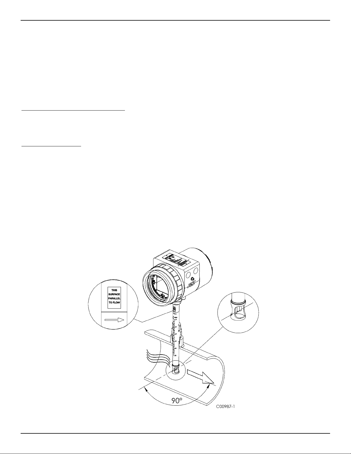
Mount the flow element to the process piping per the application piping requirements. The flow arrow etched on the element should always match
the direction of the process flow and the flat should be parallel to flow with-in +/- 3° of rotation. Flow elements with variable insertion lengths
should insert ½” inch past the centerline of the process pipe or tube and the flow direction arrow should be aligned and leveled correctly. After the
flow element has been located correctly and tightened into place, verify the process seal does not leak by slowly applying pressure until the maximum operation pressure is applied. Check for leaks at the process connection boundary using standard leak detection methods.
Figure 1. shows a properly mounted compression fitting process connection instrument.
Figure 1
Fluid Components International LLC 5
Page 10
INSTALLATION ST100 Series Flow Meter
Compression Fitting Mounting
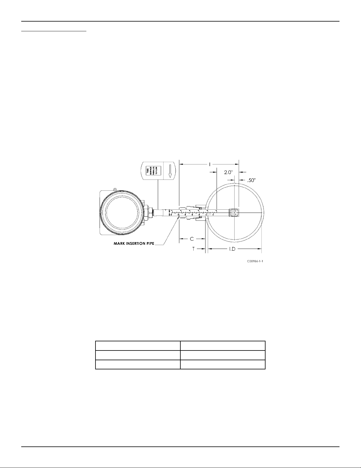
1. FCI single point insertion Flow Meters are calibrated at the centerline of the process pipe. The flow element is properly mounted when
the tip of the flow element is located 0.50 inches (13 mm) past the pipe centerline
2. I = Insertion depth
I.D. = Pipe inside diameter
T = Pipe wall thickness
C = Mounting coupling with and installed compression fitting length
Insertion Depth = I = 0.50 inches + (I.D. / 2) + T + C
3. The scale etched on the side of the insertion pipe indicates the length to the tip of the flow element.
4. Calculate the Insertion depth using the equation in step 2 above.
I = __________
5. Mark the insertion pipe at the calculated insertion depth.
Figure 2
6. Apply proper thread sealant to the tapered pipe thread on the compression fitting and secure into pipe mounting coupling.
7. Insert the flow element to the insertion depth mark and hand tighten the compression nut. Align the orientation flat parallel to the flow
direction.
8. Tighten the compression nut to the torque specified for the corresponding ferrule material. Compression fitting manufacture recommends
1-1/4 turns past hand tight.
Ferrule Material Torque
Teflon 6 FT-Lbs
316 SST 65 FT-Lbs *
Note: The metal ferrule configuration can only be tightened one time. Once tightened, the insertion length is no longer
adjustable.
6 Fluid Components International LLC
Page 11
ST100 Series Flow Meter INSTALLATION
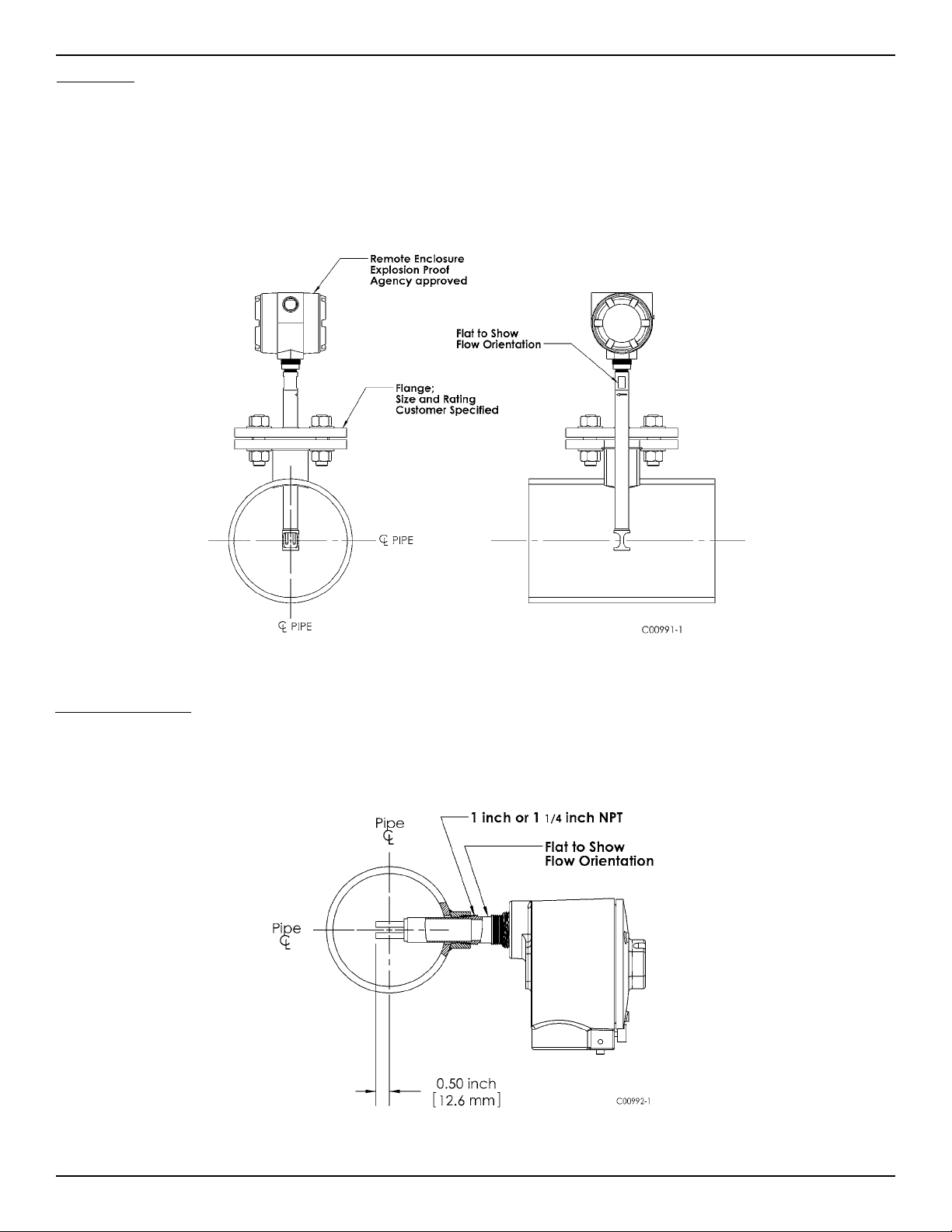
Flange Mount
The flange mount flow element in shown in Fig 3. Attach the process mating flange with care. The correct orientation of the flow element must be
maintained to ensure the calibrated accuracy.
• Verify the process media flow matches the flow direction arrow on the flow element.
• Apply appropriate gasket and or sealant to flange mount as required.
• Mate flow element flange to process flange keeping flat oriented properly.
• Secure flanges with appropriate mounting hardware.
Figure 3
NPT Pipe Thread Mount
The pipe thread configuration is shown in Fig 4. Apply sealant compatible with the process media to male threads. Carefully insert into process
mounting coupling. Tighten the flow element until snug and continue until flat and flow direction arrow are aligned with process flow.
Figure 4
Fluid Components International LLC 7
Page 12

INSTALLATION ST100 Series Flow Meter
Adjustable/Retraceable Packing Gland Mounting
Applications involving the use of packing glands should refer to drawings located in Appendix A for additional detail.
NPT and flange mounted gland are available. Isolation valves are typically used in packing gland applications.
• Follow the pipe thread or flange mount procedures as described in previous sections.
• Tighten the packing nut until the internal packing is tight enough to prevent excess process leakage but also allow the insertion pipe to be
inserted into place. Orient the flat and flow arrow properly.
• Proceed to insert the flow element into process media pipe. For the medium pressure packing gland, use the adjusting nuts on the all-thread to
pull the flow element into proper position. Tighten the opposing lock nuts.
• Tighten the packing nut another ½ to 1 turn until tight (approximately 65 – 85 ft-lbs)
• On low pressure packing glands, align the split ring collar with connecting strap on packing nut. Tighten the two ¼-28 cap screws on the split
ring locking collar.
STP100 and STP102A Flow Element Installation
The Model STP100 and STP102A add an additional pressure transducer measurement as a third process variable output. The process connections
available on the STP model include the standard connections available on the ST model except the compression fitting. The ST102 will have two
probe assemblies. Available process connections include:
• Retractable Packing Gland
• Fixed NPT
• Flanged
All flow element mounting and securing instructions for the selected process connections are identical to the ST100. These details are provided in
the previous process connection mounting sections.
The pressure limitation for the STP model will be determined by the selection of the pressure transducer. The available options include 50, 160, 500
and 1000 psig (3.44, 11.03, 34.47 and 69.95 bar) maximum pressure ranges.
The pressure transducer is offered in two different temperature service ranges:
• Standard: 32 to 176°F (0 to 80°C)
• Explosion Proof (Ex): -22 to 212°F (-300 to 100°C)
The pressure transducer is located inside the rectangular shaped enclosure attached to the flow element. The pressure tap is located in the center of
the two thermowells and extends through the center of the insertion pipe into the enclosure where the transducer is located. Because the pressure
transducer is located several feet away from the process media, at the end of a dead head tube assembly, the pressure transducer will be exposed to
the external ambient temperature of the flow element.
Flow Element Wiring
The STP100/102A can be configured with integral or remote electronics. Wiring diagrams for these configurations are located in Appendix B.
Remote configurations require a 10 conductor shielded cable as specified in the Instrument Wiring Table 1.
STP100/102A Electronics Description
The electronic transmitter for the instrument provides flow, temperature and pressure output on the display and the customer selected output
mode, analog or digital.
Analog 4-20mA output: factory default setup
•Output#1–FloworTwopointaverageFlow
•Output#2–temperatureorTwopointaverageTemperature
•Output#3–Pressure
8 Fluid Components International LLC
Page 13

ST100 Series Flow Meter INSTALLATION
HART output
•Command9–Slot0,2,4:FloworTwopointaverageFlow.
•Command9–Slot5:TemperatureorTwopointaverageTemperature
•Command9–Slot6:Pressure
Fieldbus output
•FlowAIBlock–TwopointaverageFlow
•TemperatureAIBlock–TwopointaverageProcessTemperature
•PressureAIBlock-Pressure
•ProcessTransducerblock–index13,PRIMARY_VALUE(AverageFLOW)
•ProcessTransducerblock–index15,SECONDARY_VALUE(AverageTEMPERATURE)
•ProcessTransducerblock–index19,Quaternary_VALUE(Pressure)
Modbus output
•Command3–TwopointaverageFlow
Two point average Temperature
Pressure, available on STP models
Totalizer
Troubleshooting
The “Service Mode” for both HART and Foundation Fieldbus provide access to the individual sensor output values.
The 102A electronics transmitter can recognize a disconnected flow element. If this condition is detected, the instrument will indicate a fault
condition and display process variables from the sensor that remains connected to the transmitter. The fault will self-correct when the sensor
is re-connected.
ST102A and STP102A Flow Element Installation
The Model ST/STP102A is a dual-element averaging system operating through a single transmitter. The ST/STP102A Flow Element offers the same
process connections that are available on the basic ST100. The ST/STP102A will have two probe assemblies. Available process connections include:
• Compression Fitting
• Retractable Packing Gland
• Fixed NPT
• Flanged
All flow element mounting and securing instructions for the selected process connections are identical to the ST100. These details are provided in
the previous process connection mounting sections. Each Flow element is identified with the instrument serial number followed by a -1 or -2.
For example:
Serial no: 409486-1 Description - flow element no.1
Serial no: 409486-2 Description - flow element no.2
Installed Point Locations
The flow element point locations for a two point averaging system are based from the US EPA – Method 1 Traverse Point recommendations.
This method is applicable to gas streams flowing in ducts, stacks, and flues with inside diameters greater than 12 inches. The recommended
point locations for a two point averaging system are shown in the diagram below.
Locate and secure the flow elements into position using (0.146 x Pipe I.D. + 0.50 inches) as the location dimension from the pipe I.D. to the
end of the flow element.
Fluid Components International LLC 9
Page 14

INSTALLATION ST100 Series Flow Meter
Flow Element Wiring
The ST/STP102A can be configured with one integral and one remote flow element or with two separate flow elements and remote electronics. Wiring diagrams for these configurations are located in Appendix B. Each of the flow elements on the ST102A/STP102A are connected to
the transmitter using an 8 conductor shielded cable as specified in the Instrument Wiring Table 1.
ST/STP102A Electronics Description
The electronic transmitter for the ST/STP102A type instruments provides a two point averaged flow and temperature output on the display
and the customer selected output mode, analog or digital.
Analog 4-20mA output: factory default setup
•Output#1–TwopointaverageFlow
•Output#2–TwopointaverageTemperature
•Output#3–Pressure,availableonSTPmodels
HART output
•Command9–Slot0,2,4:TwopointaverageFlow.
•Command9–Slot5:TwopointaverageTemperature
•Command9–Slot6:Pressure
Fieldbus output
•FlowAIBlock–TwopointaverageFlow
•TemperatureAIBlock–TwopointaverageProcessTemperature
•ProcessTransducerblock–index13,PRIMARY_VALUE(AverageFLOW)
•ProcessTransducerblock–index15,SECONDARY_VALUE(AvrageTEMPERATURE)
Modbus output
•Command3–TwopointaverageFlow
Two point average Temperature
Pressure, available on STP models
Totalizer
10 Fluid Components International LLC
Page 15
ST100 Series Flow Meter INSTALLATION
Troubleshooting
The “Service Mode” both HART and F
The ST/STP102A electronics transmitter can recognize a disconnected flow element. If this condition is detected, the instrument will indicate
a fault condition and display process variables from the sensor that remains connected to the transmitter. The fault will self-correct when the
sensor is re-connected.
oundation fieldbus provide access to the individual sensor output values.
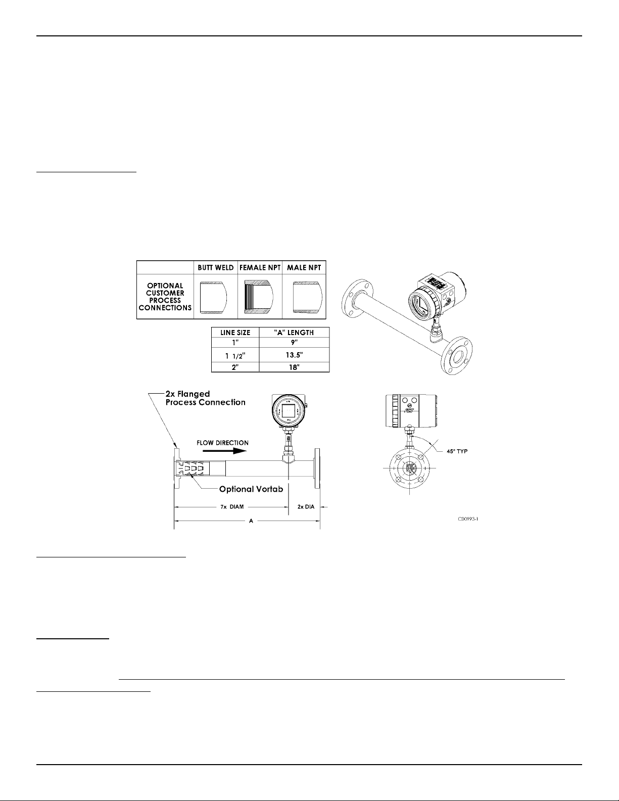
In-Line Sensor Installation
The sensor can be threaded, flanged or butt weld mounted to the process piping. The specific sensor process connection is customer specified on the
Order Information Sheet.
Mount the sensor to the process piping per the application piping requirements. Verify the flow direction arrow is pointed in the correct direction.
After the sensor head has been located correctly and tightened into place, verify the process seal does not leak by slowly applying pressure until the
normal operation pressure is applied. Check for leaks at the process connection boundary.
Figure 5
Flow Transmitter Electronics Installation
The instrument electronic transmitter can be an integral part of the flow element or it can be mounted remotely using a shielded cable between the
flow element and the electronics.
Supply connection wiring must be rated at least 90 °C.
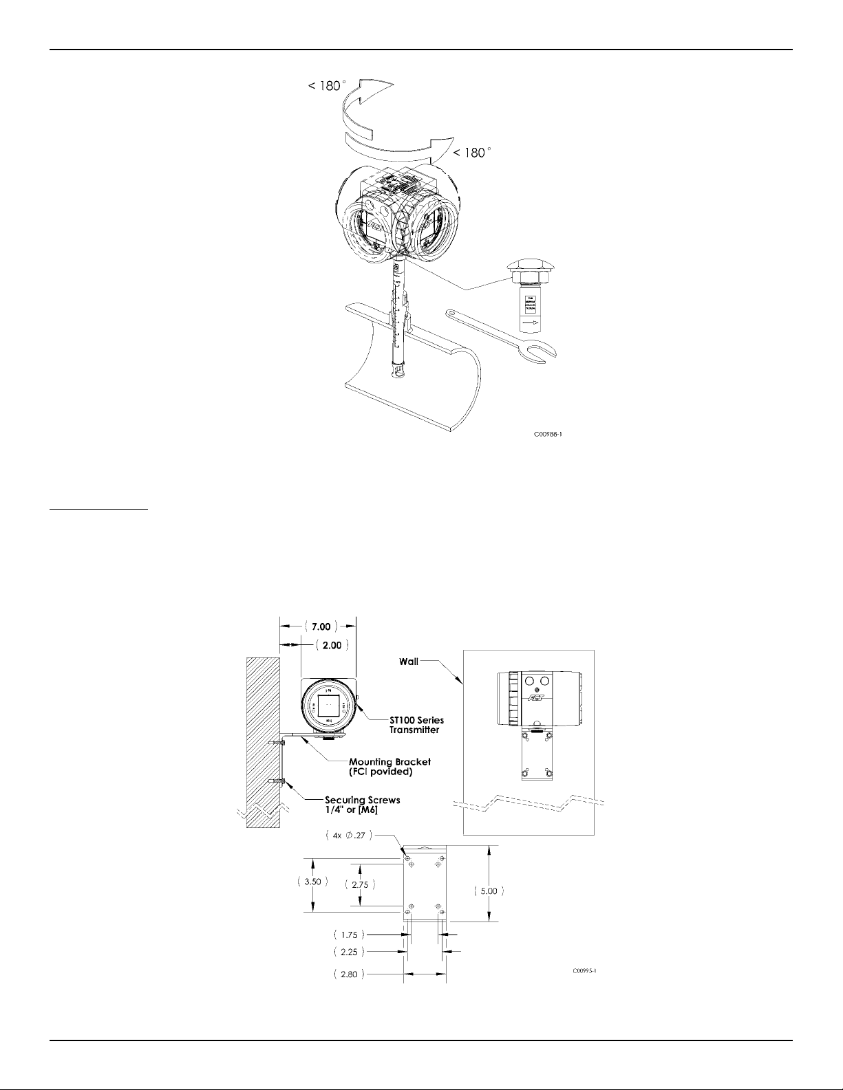
Integral Electronics
The integral electronics package is mounted during the flow element installation process. The integral electronics can be rotated +/- 180 degrees
on the top of the flow element insertion pipe. This is done by loosening the lock nut at the base of the enclosure and rotating the enclosure to the
preferred orientation. Do not rotate the electronics enclosure more than +/- 180 degrees, damage to internal wiring may result from
over rotating the enclosure!
Lock Nut Torque Specification: 30-35 ft-lbs (40-47 N-m)
The Integral electronics should be supported in applications where excessive vibration is present. A mounting bracket is available from FCI to support the electronics when additional support is required.
Fluid Components International LLC 11
Page 16
INSTALLATION ST100 Series Flow Meter
Figure 6
Remote Electronics
A mounting bracket is supplied when the Transmitter is ordered for remote mounting. The bracket mounting details are shown in Figure 7. below.
These details are also available on the Outline Installation Drawings located in appendix A. The electronics can be easily wall or pipe mounted.
The mount bracket is designed for .25 inch or M6 mounting hardware. The electronics should be securely mounted to cement or structural support
columns or beams. Mounting to plaster is not recommended and does not meet system approval requirements.
Figure 7
12 Fluid Components International LLC
Page 17
ST100 Series Flow Meter INSTALLATION
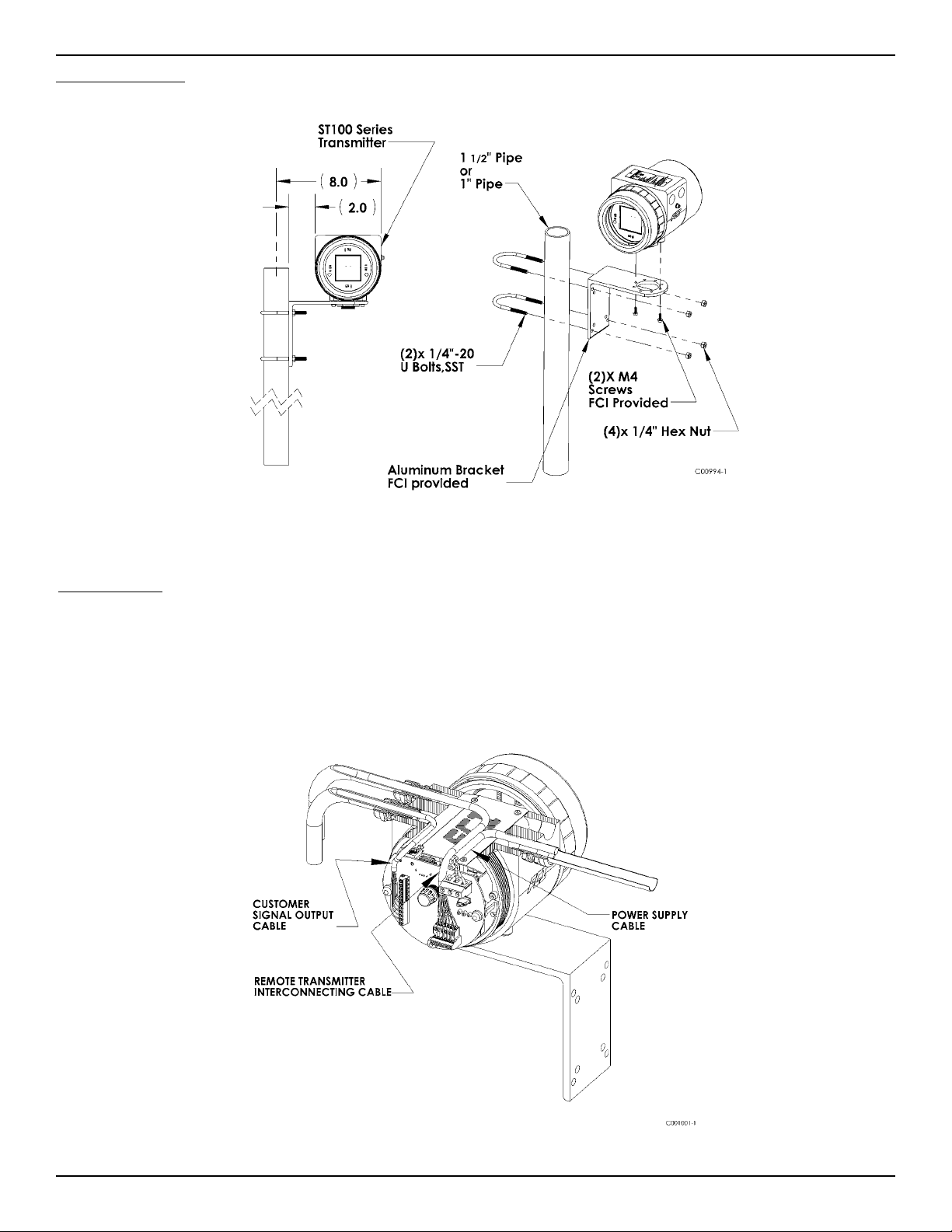
Remote Pipe Mounting
Figure 8
Instrument Wiring
The flow transmitter can be powered by 85 – 265 Vac or 24 Vdc as specified in the instrument specification. The electronics cannot be configured to
switch between AC and DC power. For 220/265 Vac installations, a neutral reference circuit must be used.
All cable glands and conduit fittings must meet or exceed the area approval rating where the instrument is being installed.
The recommended instrument wiring routing is shown in figures 15 and 16.
Figure 15
Fluid Components International LLC 13
Page 18
INSTALLATION ST100 Series Flow Meter
Figure 16
Connection 10 FT 50 FT 100 FT 250 FT 500 FT 1000 FT
Power AC or DC 22 22 22 20 18 16
Flow Element
(8 Conductor Shielded)
STP Flow Element
(10 Conductor Shielded)
Analog Out (HART) 16-30 16-30 16-30 16-30 16-30 16-30
Digital Out
Foundation Fieldbus
Modbus RS485 (14-30 AWG)
Analog output maximum load: 600 ohms
Instrument Power Requirements: See Instrument Specifications, page 8.
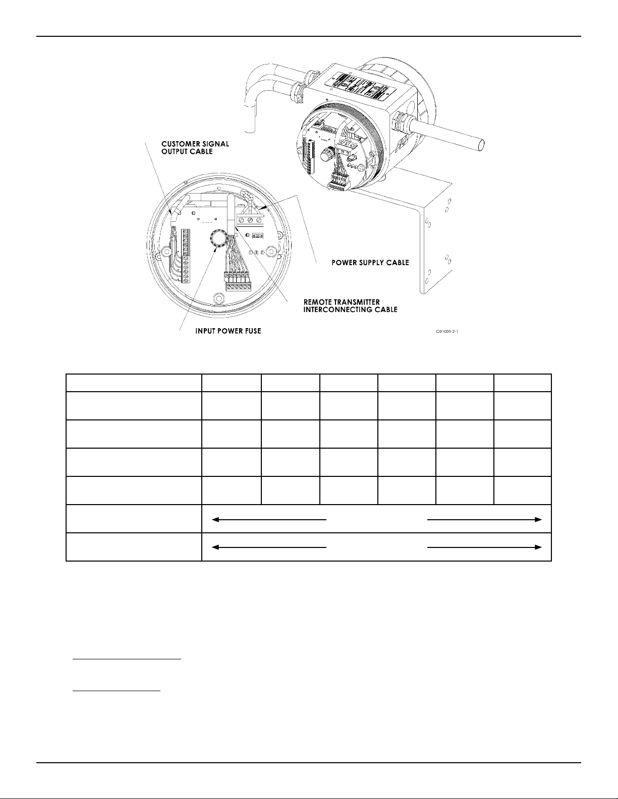
Instrument Fuse rating and part no:
AC Input Power (85 - 265 Vac):
MFR - LITTLEFUSE, 2A TR5 SLO-BLO series 383 (2 Amp rating), part no. 38312000000; FCI part no. 022499-01.
DC Input Power (24 Vdc):
MFR - LITTLEFUSE, 2A TR5 SLO-BLO series 383 (2 Amp rating), part no. 38312000000; FCI part no. 022499-01.
The input power fuse is located on the customer interface board, see figure 16. Instrument power must be turned off when
replacing the fuse. To replace the fuse, unscrew the clear fuse cover and pull the fuse straight out of the holder. Replace the fuse
with the recommended fuse listed above by aligning the fuse pins with the receiving holes located in the fuse holder and pushing
securely into place until the fuse bottoms in the holder. Replace the fuse cover.
14 Fluid Components International LLC
24 24 24 22 22 18
22 22 22 22 22 18
FF-844 H1 (14-30 AWG)
Instrument Wiring Table 1 - Recommended AWG
Page 19
ST100 Series Flow Meter INSTALLATION
Reference the following wiring diagrams in Appendix B for specific integral and remote mounted electronics.
Figure B-1 : Integral - AC Input Power, Analog and HART Output
Figure B-2 : Remote - AC Input Power, Analog and HART Output
Figure B-3 : Integral - DC Input Power, Analog and HART Output
Figure B-4 : Remote - DC Input Power, Analog and HART Output
Figure B-5 : Integral - AC Input Power, Foundation fieldbus Output
Figure B-6 : Remote - AC Input Power, Foundation fieldbus Output
Figure B-7 : Integral - DC Input Power, Foundation fieldbus Output
Figure B-8 : Remote - DC Input Power, Foundation fieldbus Output
ST102/STP102
Figure B-16 : Flow Element Connection - Integral/Remote
Figure B-17 : Flow Element Connection - Remote
Figure B-9 : Integral - AC Input Power, Modbus Output
Figure B-10 : Remote - AC Input Power, Modbus Output
Figure B-11 : Integral - DC Input Power, Modbus Output
Figure B-12 : Remote - DC Input Power, Modbus Output
Figure B-13 : Remote - 8 Conductor Interconnection Cable
Figure B-14 : Source - Pulse/Fequency Output
Figure B-15 : Sink - Pulse/Fequency Output
STP100/STP102
Figure B-18 : Remote - 10 Conductor Interconnection Cable
Post Installation Check
Verify all wiring connections are secure and correct to the appropriate wiring diagram. Verify the flow direction arrow on the flow element is pointing
in the correct direction. Verify the mechanical process connection is secure and meets the system pressure requirements.
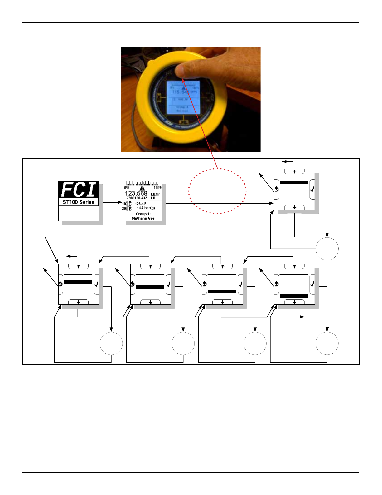
Basic Commissioning and Start-Up
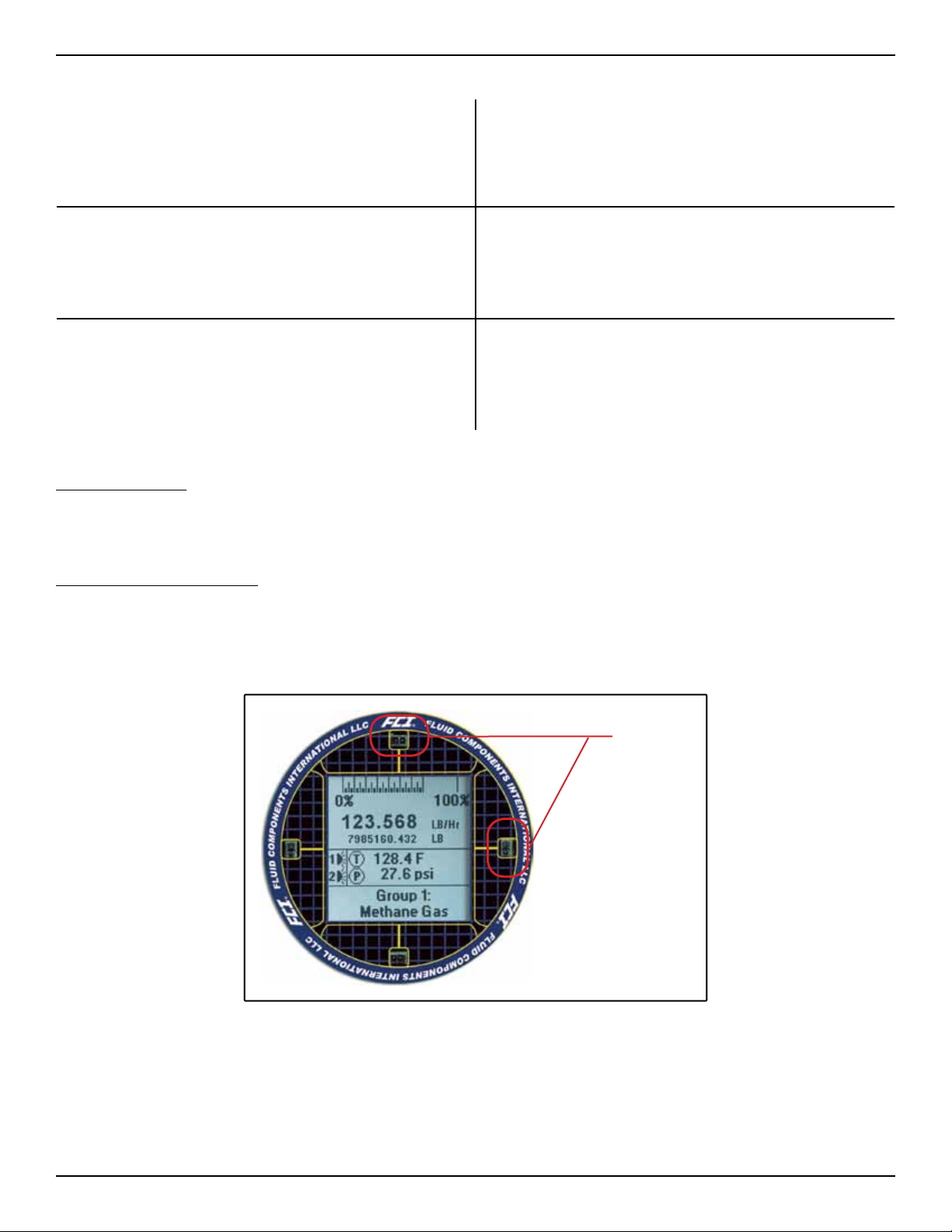
When all wiring and process connections have been verified, apply power to the instrument. The instruments with the LCD will briefly show a
welcome screen indicating the software version followed by the normal operation process screen. The normal process screen indicates process flow
rate, total flow, temperature and pressure depending on the options ordered. The calibration group and group description are also displayed at the
bottom of the screen. Verify the process variable engineering units are correct.
I.R. Sensors
(4 places)
Normal Operation Process Screen
The instrument LCD display functions as a basic HMI setup tool. The four buttons (IR sensors) located at the 3, 6, 9 and 12 o’clock positions on the
display provide access to the basic setup parameters. The screen flow is shown in figure 18. The HMI setup menu can be accessed thru the window
without removing the electronics enclosure lids. This is done by holding your finger in front of the 12 o’clock sensor for 3 seconds. The LCD acknowledges the button selection by inverting the display characters and background while the button is held.
Fluid Components International LLC 15
Page 20
INSTALLATION ST100 Series Flow Meter
To enter HMI display menu, cover 12 o’clock button for 3 senconds.
...
T
Welcome Screen Process Screen
5 second
warmup
Aug 8, 2009
Version 1.0
Press and Hold
Press and Hold
Top Button for
Top
Button for 3 seconds
3 seconds
o
Pr
Sc
o
c
r
e
e
n
e
s
s
Options
Select Group
Alarm Ack
Diagnostics
Set-up
SD Card
...
Select
Group
...
Setup
T
o
Pr
Sc
o
c
r
e
e
n
e
s
s
Options
Select Group
Alarm Ack
Diagnostics
Set-up
SD Card
...
SD Card
T
o
Pr
Sc
o
c
r
e
e
n
e
s
s
Options
Select Group
Alarm Ack
Diagnostics
Set-up
SD Card
Alarm Ack
T
o
Pr
Sc
o
c
r
e
e
n
e
s
s
Options
Select Group
Alarm Ack
Diagnostics
Set-up
SD Card
Diagnostic
T
o
Pr
Sc
o
c
r
e
e
n
e
s
s
Options
Select Group
Alarm Ack
Diagnostics
Set-up
SD Card
Figure 18: LCD/HMI Basic Screen Flow
16 Fluid Components International LLC
Page 21

ST100 Series Flow Meter INSTALLATION
HMI Display Navigation
The four IR sensors are used to navigate the HMI menu structure. The top and bottom sensors are used to scroll thru the menu selections. The right
sensor button is used to select and the left sensor button is used to return to the previous menu.
Scroll Up
Go Back / Escape
Scroll Down
Enter/Select
The setup menu allows the user to modify all process variable engineering units and the pipe dimensions. The basic functions that that are accessible from the HMI menu are listed below:
1. Select Group (5 calibrations groups are available)
2. Acknowledge Alarms
3. Identify system faults
4. Set up:
Process variable engineering units
Pipe dimensions
Display orientation
Display contrast
5. SDcard remove and insert acknowledgment
HMIuserpassword:E#C
The HMI provides access to some of the basic instrument setup features. This allows the user to make configuration changes to the instrument without opening the enclosure lids. The ST100 PC interface configuration application provides an alternate method of configuring the
instrument. The PC configuration application is easy to use and is the recommended configuration tool when commissioning the instrument.
The ST100 configuration software instructions are provide in a supplement manual, FCI document number 06EN003403.
*ON display indicates PC Configuration Application is connected.
Fluid Components International LLC 17
Page 22

INSTALLATION ST100 Series Flow Meter
System Fault and Alarm Indication
The ST100 LCD Display indicates both alarm and fault conditions with a caution triangle icon directly above the flow rate indication on the
LCD.
Fault/Alarm Icon
When an alarm condition is met, the indicator will flash on and off. The flashing condition will continue until the alarm condition no longer
exists or the alarm is acknowledged using the HMI display menu. The alarm indicator can also be turned off by disabling the condition
through the configurator alarm Tab.
Instrument fault codes can be viewed by selecting the Diagnostics branch in the configurator tree or the HMI display menu.
Functions
Real Time Clock Setup
The ST100 clock reset function is accessed via the ST100 Configurator. Reference the ST100 Configuration supplemental manual for installation instructions, FCI document number 06EN003403. The Configuration program is installed on a PC or Laptop computer and can be connected via the USB or Ethernet. The USB is the primary mode of communication with the ST100.
Welcome Screen
To access the ST100 Clock Reset Function: 2
1. Connect a USB cable between the computer with the Configuration Application installed and the USB connection on the interface board.
2. Select the ST100 Configurator icon to open the application. The application will open to the welcome screen as shown above.
3. Select the USB Connect button at the top of the screen. The Configuration application will open to the Process Data screen as shown
below.
18 Fluid Components International LLC
Page 23

ST100 Series Flow Meter INSTALLATION
4. Select the Advanced Setup menu in the left menu tree.
Select the Date and Time Tab at the top of the page.
5.
Select the “Get from Device” button at the bottom of the page.
6.
7. Set the correct Date and Time.
Press the “Send to Device” button. (User password: 2772)
8. Verify the Date and Time have been set correctly by pressing the “Get from Device” button.
Fluid Components International LLC 19
Page 24

INSTALLATION ST100 Series Flow Meter
Totalizer
The Flow totalizer function accumulates the instrument total flow, very much like the odometer on an automobile. The engineering flow units
must be set in mass or volumetric units for this function to work. The total flow value is displayed directly below the real time flow value on
the instrument LCD display.
Total
Flow Value
Totalizer Setup
The ST100 totalizer function is accessed via the ST100 Configurator. Reference the ST100 Configuration supplemental manual for installation
instructions, FCI document number 06EN003403. The Configuration program is installed on a PC or Laptop computer and can be connected via
the USB or Ethernet. The USB is the primary mode of communication with the ST100.
To access the ST100 Totalizer Function:
1. Connect a USB cable between the computer with the Configuration Application installed and the USB connection on the interface board.
2. Select the ST100 Configurator icon to open the application. The application will open to the welcome screen as shown above.
3. Select the USB Connect button at the top of the screen. The Configuration application will open to the Process Data screen as shown
below.
Welcome Screen
20 Fluid Components International LLC
Page 25

ST100 Series Flow Meter INSTALLATION
4. Select the Basic Setup menu in the left menu tree
(User password: 2772)
Process Data Screen
5.
Select the Totalizer tab at the top of the page.
6. Select the “Totalizer Enabled” box.
7. Select the “Show Totalizer Value” box.
8. Select the “Send to Device” button.
Basic Setup Totalizer Tab Screen
The total flow value will now be displayed on the Instrument LCD display and the Process Data screen on the ST100 Configuration Application. The total flow value can be reset to zero using the “Reset Totalizer to Zero” button on the Basic Setup Totalizer screen.
Fluid Components International LLC 21
Page 26

INSTALLATION ST100 Series Flow Meter
Data Logging
The ST100 SD Card Logging features can be accessed via the ST100 Configurator Reference the ST100 Configuration supplemental manual for
installation instructions, FCI document number 06EN003403. The Configuration program is loaded on a PC or Laptop and can be connected via
the USB or Ethernet. The USB is the primary mode of communication with the ST100.
Welcome Screen
To access the ST100 Logging Function:
1. Connect a USB cable between the computer with the Configuration Application installed and the USB connection on the interface board.
2. Select the ST100 Configurator icon to open the application. The application will open to the welcome screen as shown above.
3. Select the USB Connect button at the top of the screen. The Configuration application will open to the Process Data screen as shown
below.
Process Data Screen
22 Fluid Components International LLC
Page 27

ST100 Series Flow Meter INSTALLATION
4. Select the Basic Setupinthemenulocatedintheleftmenu.ThenselecttheSDCardLoggingTab.YoushouldnowseetheLogging
setup menu as shown below.
Basic Setup, SD Card Logging Tab Screen
A logging session can be started by 2 different methods:
• Automatic when the SD card s present during an instrument power up.
• Manually using the ST100 Configuration Application.
Manual Start Logging Method
1. Begin with the Instrument power On and the Instrument connect to the Configuration Application thru
the USB port. Verify a memory card is inserted into the card slot on the back side of the interface
circuit board. The card should be inserted as shown with the contacts facing up. Inserting the
SD card upside down will cause damage to the socket. The card will click into position when
properly inserted.
2. Using the Logging Setup Menu in the ST100 Configuration Application:
• Press the “Remove Micro SD Card” button in the Logging setup Menu, this will close any logging
session that might be in progress.
(User Level Password = 2772)
• Select the Logging time interval.
• Press the “Send to Device” button.
• Press the “Insert Micro SD Card” button, the user may be prompted for a password, enter 2772 and press enter.
• The instrument begins logging Process Data.
• Press the “Remove Micro SD Card” button to close the logging file.
• Remove the SD Micro Card and open the log file as a .csv format. Each log file session creates a log file with a name format:
Logyymmddhhmmss.csv
Where:
yy is the 2 digit year
mm is the 2 digit month
dd is the 2 digit day
hh is the 2 digit hour
mm is the 2 digit minute
ss is the 2 digit second
Example File Name: Log110524134322
Note: The date and time information is retrieved from the real-time clock on the STAK CORE. If there is no battery installed, and/or if the date
and time have not been set prior to the initiation of the logging session, this could result in erroneous log file names.
Fluid Components International LLC 23
Page 28

INSTALLATION ST100 Series Flow Meter
Log File Contents
Log Entry Format
Each log entry consists of a single line (row) of data.
Each log entry is of a similar format:
<year>,<month>,<day>,<timestamp “hh:mm:ss”>,<tag>,<data 1>, <data 2>,…
Where:
<year> is the 4 digit year
<month> is the 2 digit month
<day> is the 2 digit day
<timestamp> is the time of day in hours (2 digit): minutes (2 digit) : seconds (2 digits)
<tag> is the 2 character entry type identifier
<data 1> <data 2> are the entry type specific data items
Log Entries
There are different types of log entries, and these are identified by the unique 2 character “tag” field. The data following the tag varies
depending on the type of log entry. A listing of the Tags and the associated description is shown below.
Tag Tag Description
PD Process Data
FL Fault
CF Core Fault
AL Alarm Activation
DR Automatic Delta-R test
Process Data – tag PD
Aprocessdataentryisaddedtotheloglebasedonthefrequencyofloggingspeciedviathe“0Q”CLIcommand.
Following the tag field, the data items are (in this order):
• Flow (in customer units)
• Temperature (in customer units)
• Pressure (in customer units)
• Totalizer (if present, in customer units. If totalizer not enabled, then “0.0”)
• CORE fault bitmap (8 character hexadecimal) for factory use
• FE0 fault bitmap (8 character hexadecimal) for factory use
• FE1 fault bitmap (8 character hexadecimal) for factory use
year month day time tag flow temp press Total fault code fault code fault code
2011 5 24 13:44:09 PD 0 85.87962 0 0x00100000 0x00000001 0x00000000
2011 5 24 13:44:39 PD 0 85.88636 0 0x00100000 0x00000001 0x00000000
2011 5 24 13:45:09 PD 0 85.88426 0 0x00100000 0x00000001 0x00000000
2011 5 24 13:45:39 PD 0 85.89391 0 0x00100000 0x00000001 0x00000000
Log File Entry Example: Instrument is in a no flow condition
24 Fluid Components International LLC
Page 29

ST100 Series Flow Meter INSTALLATION
Alarm Activation/Deactivation – tag AL
When an alarm condition either activates (alarm condition met) or deactivates (alarm condition no longer present), an alarm log entry will be
generated.
Following the tag field, the data items are:
• Alarm Id (1..6)
• Activated (1) or Deactivated (0)
• Alarm mode:
o Flow high: 1
o Flow low: 2
o Temperature high: 3
o Temperature low: 4
o Pressure high: 5
o Pressure low: 6
• Alarm process data value
o If Alarm mode 1 or 2, then flow (in customer units)
o If Alarm mode 3 or 4, then temperature (in customer units)
o If Alarm mode 5 or 6, then pressure (in customer units)
year month day time tag Alarm IDAct/
De-Act
2011 5 24 13:44:09 AL 1 1 2 0 0x00100000 0x00000001 0x00000000
2011 5 24 13:44:39 AL 2 1 3 86.63182 0x00100000 0x00000001 0x00000000
Log File Entry Example: Alarm 1 and 2 activated
FE Self Test: Delta-R – tag DR
When an automatic Delta-R test for an FE is executed, the results are logged with a Delta-R log entry.
Following the tag field, the data items are:
• FE Id (0..15)
• Delta-R low measured flow value (in customer units)
• Delta-R low expected flow value (in customer units)
• Delta-R medium measured flow value (in customer units)
• Delta-R medium expected flow value (in customer units)
• Delta-R high measured flow value (in customer units)
• Delta-R high expected flow value (in customer units)
year month day time tag FE ID DR low m DR low e DR med m DR low e DR hi m DR hi e
2011 5 24 13:44:39 DR 0 60.48953 60.48953 100.48953 100.48953 150.48953 150.48953
Mode PD value fault code fault code fault code
Log File Entry Example: Automatic Delta R Calibration Check
Note: This log function is setup in the Diagnostic menu under the Scheduled Tests tab
Two other tag codes will be logged if the instrument identifies a system fault. These additional tags are FL and CF. If these fault tags are
identified in a log file, contact FCI customer service.
Fluid Components International LLC 25
Page 30

INSTALLATION ST100 Series Flow Meter
Intentionally Left Blank
26 Fluid Components International LLC
Page 31

ST100 Series Flow Meter APPENDIX A - OUTLINE DIMENSIONAL DRAWINGS
APPENDIX A - OUTLINE DIMENSIONAL DRAWINGS
Fluid Components International LLC 27
Page 32

APPENDIX A - OUTLINE DIMENSIONAL DRAWINGS ST100 Series Flow Meter
28 Fluid Components International LLC
Page 33

ST100 Series Flow Meter APPENDIX A - OUTLINE DIMENSIONAL DRAWINGS
Fluid Components International LLC 29
Page 34

APPENDIX A - OUTLINE DIMENSIONAL DRAWINGS ST100 Series Flow Meter
D
APPROVED
1
DATE
REVISIONS
DESCRIPTION
REV
1.13
1 1/4 INCH NPT PROCESS CONNECTION,
LOW PRESSURE PACKING GLAND.
(TEFLON OR GRAPHITE PACKING MATERIAL)
6
4 3 2
29
"FP" STYLE HEAD
"S" STYLE HEAD
C
"U" LENGTH
159
6.25
GROUNDING SCREW
4X CONDUIT PORTS
1/2 INCH NPT OR M20
197
7.75
B
SPECIFICATIONS:
CUSTOMER:
PURCHASE ORDER NO:
CUSTOMER ORDER NO:
WETTED SURFACE MATERIAL:
108
83
TYP
.31
8
279
11.0
.25
127
5.0
6.35
A
FLUID COMPONENTS
INTERNATIONAL LLC
R
SAN MARCOS, CA 92078
HAZ LOC / TYPE 4X / IP67
REMOTE ELECTRONICS ASSEMBLY
TRANSMITTER, ST100, 1 1/4 INCH NPT PGL
TITLE
06/10/11
APPROVALS
MAX ELEMENT OPERATING TEMP:
PROCESS CONNECTION:
PACKING MATERIAL:
"U" LENGTH:
SERIAL NO.(S):
TAG NO.(S):
DRAWN
FOUAD.C
CHECK
ONLINE/INSTALLATION DRAWING
4.25
3.25
1.75
.75
44
19
2.25
57
APPROVALS
CONTRACT NO.
CONTRACT
±1/2°
ANGULAR
NOTED
TOLERANCES
DIMENSIONS ARE IN INCHES
.X ±.1
UNLESS OTHERWISE SPECIFIED
.XX ±.03
DECIMALS
.XXX ±.010
MATERIAL
USED ON
USED_ON-XX
APPLICATION
THIRD ANGLE PROJECTION
NEXT ASSY
NEXT_ASSY
-
REV
1 OF 1
1
SHEET
004852
NONE
SCALE
DWG NO.
64818
CAGE CODE
D
SIZE
ENGR
3 2
MFGQAQUAL
.030
MACH RAD:
PARTS TO BE FREE OF
BURRS & SHARP EDGES
DO NOT SCALE DRAWING
FINISH: 125 RMS
MACH SURFACE
4
MOUNTING ORIENTATION OF FLAT
TO BE PARALLEL TO FLOW
LOCKING COLLAR
7 6 5
4.68
NOTICE OF PROPRIETARY RIGHTS
8
LOCAL ENCLOSURE MEETS EXPLOSION
PROOF WATER AND DUST TIGHT APPROVALS.
you is expressly conditioned upon your assent that its use is limited to use within your company
without prior written consent of FCI.
This document contains confidential technical data, including trade secrets and proprietary
information which is the property of Fluid Components International (FCI). Disclosure of this data to
only (and does not include manufacture or processing uses). Any other use is strictly prohibited
119
(SEE MANUAL FOR SPECIFIC APPROVAL TYPES)
D
MAX
91
3.60
123
4.86
109
4.28
1 INCH NPT PORT
137
5.40
GLAND ASSEMBLY
FLOW ELEMENNT AND PACKING
C
178
7.00
127
5.00
REMOTE ENCLOSURE MEETS
STAINLESS STEEL TAG
3/4 INCH PLUG
DISPLAY
2X M4 SCREWS
EXPLOSION PROOF WATER
AND DUST TIGHT APPROVALS.
(SEE MANUAL FOR SPECIFIC
APPROVAL TYPES)
REMOTE ELECTRONICS ASSEMBLY
B
MOUNTING BRACKET,
ALUMINUM
C].
C].
F [454
F [260
7 6 5
8
PACKING GLAND SPECIFICATIONS:
- MAXIMUN OPERATING TEMPERATURE, TEFLON PACKING: 500
- MAXIMUM OPERATING PRESSURE: 50 PSIG [3.5 BAR(G)].
5. SEE INSTRUMENT MANUAL FOR ADDITIONAL INFORMATION
AND INSTRUCTION.
4. ALL ORIENTATIONS AND/OR MOUTING REFERENCES ARE INDICATED FROM TERMINAL
ENCLOSURE END OF SENSING ELEMENT.
6.
- MAXIMUM OPERATING TEMPERATURE, GRAPHITE PACKING: 850
3. FOR ELECTRICAL OPTIONS, CONNECTIONS AND TESTS, SEE APPLICABLE WIRING DIAGRAM.
NOTES: UNLESS OTHERWISE SPECIFIED
2. THIS DRAWING IS REFERENCE DOCUMENT ONLY.
1. DIMENSIONS IN BRACKET [ ] ARE IN MILLIMETERS.
A
30 Fluid Components International LLC
Page 35

ST100 Series Flow Meter APPENDIX A - OUTLINE DIMENSIONAL DRAWINGS
1
4 3 2
APPROVED
DATE
REVISIONS
DESCRIPTION
REV
7
13.00
330
38
1.50
"U" LENGTH
MAX
165
6.50
MIN
2.25
57.15
MAX
D
1.13
29
1 1/4 INCH NPT PROCESS CONNECTION,
LOW PRESSURE PACKING GLAND.
(TEFLON OR GRAPHITE PACKING MATERIAL)
6
MOUNTING ORIENTATION OF FLAT
TO BE PARALLEL TO FLOW
C
"S" STYLE HEAD
"FP" STYLE HEAD
GROUNDING SCREW
4X CONDUIT PORTS
1/2 INCH NPT OR M20
197
7.75
2X ADJUSTING RODS
B
SPECIFICATIONS:
CUSTOMER:
PURCHASE ORDER NO:
CUSTOMER ORDER NO:
WETTED SURFACE MATERIAL:
108
83
TYP
.31
8
279
11.0
.25
127
5.0
6.35
A
FLUID COMPONENTS
INTERNATIONAL LLC
R
SAN MARCOS, CA 92078
HAZ LOC / TYPE 4X / IP67
REMOTE ELECTRONICS ASSEMBLY
TRANSMITTER, ST100, 1 1/4 INCH NPT PGM
TITLE
06/10/11
APPROVALS
MAX ELEMENT OPERATING TEMP:
PROCESS CONNECTION:
PACKING MATERIAL:
"U" LENGTH:
SERIAL NO.(S):
TAG NO.(S):
DRAWN
FOUAD.C
CHECK
ONLINE/INSTALLATION DRAWING
4.25
3.25
19
.75
44
1.75
57
2.25
MOUNTING BRACKET,
ALUMINUM
APPROVALS
CONTRACT NO.
CONTRACT
±1/2°
ANGULAR
NOTED
TOLERANCES
DIMENSIONS ARE IN INCHES
.X ±.1
UNLESS OTHERWISE SPECIFIED
.XX ±.03
DECIMALS
.XXX ±.010
MATERIAL
USED ON
USED_ON-XX
APPLICATION
THIRD ANGLE PROJECTION
NEXT ASSY
NEXT_ASSY
-
REV
1 OF 1
1
SHEET
004877
NONE
SCALE
DWG NO.
64818
CAGE CODE
D
SIZE
ENGR
3 2
MFGQAQUAL
.030
MACH RAD:
PARTS TO BE FREE OF
BURRS & SHARP EDGES
DO NOT SCALE DRAWING
FINISH: 125 RMS
MACH SURFACE
4
"U" LENGTH +
7 6 5
4.28
109
4.86
123
8.00
203
178
7.00
LOCKING COLLAR
5.00
127
REMOTE ENCLOSURE MEETS
EXPLOSION PROOF WATER
AND DUST TIGHT APPROVALS.
(SEE MANUAL FOR SPECIFIC
APPROVAL TYPES)
DISPLAY
2X M4 SCREWS
3/4 INCH PLUG
C].
C].
F [454
F [260
7 6 5
STAINLESS STEEL TAG
140
5.53
NOTICE OF PROPRIETARY RIGHTS
8
you is expressly conditioned upon your assent that its use is limited to use within your company
This document contains confidential technical data, including trade secrets and proprietary
information which is the property of Fluid Components International (FCI). Disclosure of this data to
only (and does not include manufacture or processing uses). Any other use is strictly prohibited
LOCAL ENCLOSURE MEETS EXPLOSION
PROOF WATER AND DUST TIGHT APPROVALS.
(SEE MANUAL FOR SPECIFIC APPROVAL TYPES)
without prior written consent of FCI.
D
1 INCH NPT PORT
GLAND ASSEMBLY
FLOW ELEMENNT AND PACKING
C
REMOTE ELECTRONICS ASSEMBLY
DEPICTS SUPPORT ROD AND ENCLOSURE POSITION WHEN FULLY INSERTED.
PACKING GLAND SPECIFICATIONS:
- MAXIMUN OPERATING TEMPERATURE, TEFLON PACKING: 500
7.
- MAXIMUM OPERATING PRESSURE: 250 PSIG [17 BAR(G)].
5. SEE INSTRUMENT MANUAL FOR ADDITIONAL INFORMATION
6.
- MAXIMUM OPERATING TEMPERATURE, GRAPHITE PACKING: 850
B
AND INSTRUCTION.
4. ALL ORIENTATIONS AND/OR MOUTING REFERENCES ARE INDICATED FROM TERMINAL
ENCLOSURE END OF SENSING ELEMENT.
3. FOR ELECTRICAL OPTIONS, CONNECTIONS AND TESTS, SEE APPLICABLE WIRING DIAGRAM.
2. THIS DRAWING IS REFERENCE DOCUMENT ONLY.
A
8
NOTES: UNLESS OTHERWISE SPECIFIED
1. DIMENSIONS IN BRACKET [ ] ARE IN MILLIMETERS.
Fluid Components International LLC 31
Page 36

APPENDIX A - OUTLINE DIMENSIONAL DRAWINGS ST100 Series Flow Meter
32 Fluid Components International LLC
Page 37

ST100 Series Flow Meter APPENDIX A - OUTLINE DIMENSIONAL DRAWINGS
Fluid Components International LLC 33
Page 38

APPENDIX A - OUTLINE DIMENSIONAL DRAWINGS ST100 Series Flow Meter
34 Fluid Components International LLC
Page 39

ST100 Series Flow Meter APPENDIX A - OUTLINE DIMENSIONAL DRAWINGS
Fluid Components International LLC 35
Page 40

APPENDIX A - OUTLINE DIMENSIONAL DRAWINGS ST100 Series Flow Meter
Intentionally Left Blank
36 Fluid Components International LLC
Page 41

ST100 Series Flow Meter APPENDIX B - WIRING DIAGRAMS
APPENDIX B - WIRING DIAGRAMS
Fluid Components International LLC 37
Page 42

APPENDIX B - WIRING DIAGRAMS ST100 Series Flow Meter
Figure B-1: Integral - AC Input Power, Analog and HART Output
Figure B-2: Remote - AC Input Power, Analog and HART Output
38 Fluid Components International LLC
Page 43

ST100 Series Flow Meter APPENDIX B - WIRING DIAGRAMS
Figure B-3: Integral - DC Input Power, Analog and HART Output
Figure B-4: Remote - DC Input Power, Analog and HART Output
Fluid Components International LLC 39
Page 44

APPENDIX B - WIRING DIAGRAMS ST100 Series Flow Meter
Figure B-5: Integral - AC Input Power, Foundation fieldbus Output
Figure B-6: Remote - AC Input Power, Foundation fieldbus Output
40 Fluid Components International LLC
Page 45

ST100 Series Flow Meter APPENDIX B - WIRING DIAGRAMS
Figure B-7: Integral - DC Input Power, Foundation fieldbus Output
Figure B-8: Remote - DC Input Power, Foundation fieldbus Output
Fluid Components International LLC 41
Page 46

APPENDIX B - WIRING DIAGRAMS ST100 Series Flow Meter
Figure B-9: Integral - AC Input Power, Modbus Output
Figure B-10: Remote - AC Input Power, Modbus Output
42 Fluid Components International LLC
Page 47

ST100 Series Flow Meter APPENDIX B - WIRING DIAGRAMS
Figure B-11: Integral - DC Input Power, Modbus Output
Figure B-12: Remote - DC Input Power, Modbus Output
Fluid Components International LLC 43
Page 48

APPENDIX B - WIRING DIAGRAMS ST100 Series Flow Meter
Figure B-13: Remote - 8 Conductor Interconnection Cable
Figure B-14: Source - Pulse/Fequency Output
44 Fluid Components International LLC
Page 49

ST100 Series Flow Meter APPENDIX B - WIRING DIAGRAMS
Figure B-15: Sink - Pulse/Fequency Output
Figure B-16: Flow Element Connection - Integral/Remote
Fluid Components International LLC 45
Page 50

APPENDIX B - WIRING DIAGRAMS ST100 Series Flow Meter
123456789
REF SEN
REF EXC
RTD GND
ACT SEN
GND SEN
HTR EXC #1
ACT EXC
HTR RTN
10
SIGN -
SIGN +
LOCAL ENCLOSURE
7
HTR EXC #1
8 HTR RTN
6 ACT EXC
4 ACT SEN
2 GND SEN
1 RTD GND
5 REF EXC
3 REF SEN
9 SIGN +
10 SIGN -
Figure B-17: Flow Element Connection - Remote
ACT EXC 4
GND SEN 6
REF EXC 8
10 CONDUCTOR SHIELDED CABLE
SHIELD 10
PRESS - 12
HTR EXC #1 1
HTR RTN 3
ACT SEN 5
GND 7
REF SEN 9
PRESS + 11
TRANSMITTER
C01062-1-1
Figure B-18: Remote - 10 Conductor Interconnection Cable
46 Fluid Components International LLC
Page 51

ST100 Series Flow Meter APPENDIX C - APPROVALS
APPENDIX C APPROVALS
EC DECLARATION OF CONFORMITY ST100 SERIES
We, Fluid Components International LLC, located at 1755 La Costa Meadows Drive, San Marcos,
California 92078-5115 USA, declare under our sole responsibility that the ST100 Flowmeter Product
Family, to which this declaration relates, is in conformity with the following directives and specifications.
Directive 94/9/EC ATEX
IECEx Scheme
Certified by FM Approvals LLC: 1151 Boston-Providence Turnpike, Norwood, MA 02062, USA
EC-Type Examination Certificates:
FM12ATEX0016X satisfies EN 60079-0: 2009, EN 60079-1: 2007, EN 60079-31: 2009,
EN 60529 1991+A1:2000 requirements for use in hazardous areas.
IECEx FMG 12 0003X satisfies IEC 60079-0: 2007-10, IEC 60079-1: 2007-04, IEC 60079-31: 2008
requirements for use in hazardous areas.
Hazardous Areas Approval FM12ATEX0016X / IECEx FMG 12 0003X for:
Category II 2 G Ex d IIC T6/T1 Gb Ta = -40ºC to +65ºC
Category II 2 D Ex tb IIIC T85ºC/ T450ºC Db Ta = -40ºC to +65ºC; IP67
Directive 2004/108/EC Electromagnetic Compatibility EMC
Immunity specification
Emissions specification
Directive 2006/95/EC Low Voltage
Electrical Safety Specification
Directive 97/23/EC Pressure Equipment
The ST100L Model is in conformity with the sound engineering practices as defined in article 3,
paragraph of PED 97/23/EC.
Issued at San Marcos, California USA
26, September 2012
: EN 61000-6-2: 2005
: EN 61000-6-4: 2007
: EN 61010-1: 2001, 2nd Edition
Eric Wible
______________________________________
Eric Wible, Engineering Manager
1755 La Costa Meadows Drive, San Marcos, California 92078 USA 760-744-6950 800-854-1993 760-736-6250
European Office: Persephonestraat 3-01 5047 TTTilburg – The Netherlands – Phone 31-13-5159989 Fax 31-13-5799036
Doc no. 23EN000024A
2012.09.26 14:41:20 -07'00'
Flow/Liquid Level/Temperature Instrumentation
Visit FCI on the Worldwide Web: www.fluidcomponents.com
Fluid Components International LLC 47
Page 52

APPENDIX C - APPROVALS ST100 Series Flow Meter
TAG, UNIT CERTIFICATION, FM c,us, ATEX, IECEx
48 Fluid Components International LLC
Page 53

ST100 Series Flow Meter APPENDIX C - APPROVALS
Safety Instructions for the use the ST100 Series flowmeter in Hazardous Areas
Approval FM12ATEX0016X/IECEx FMG12.0003X for:
Category II 2 G for Gas protection Ex d IIC T6…T1
Category II 2 D for Dust protection Ex tb IIIC T85ºC…T450ºC; IP67
The ST100 Series consist of a sensing element and associated integral or remote mounted electronics mounted in a type
“d” flameproof enclosure.
Relation between ambient temperature, process temperature and temperature class is as follows:
Ambient temperature range (Ta): T6 [85ºC] for : -40ºC <Ta< + 65ºC
Process temperature range (Tp): T5 [T100ºC] for : -40ºC <Tp< + 65ºC
T4 [T135ºC] for : -40ºC <Tp< + 65ºC
T2 [T300ºC] for : -40ºC <Tp< + 177ºC
T1 [T450ºC] for : -40ºC <Tp< + 450ºC
Electrical data: Power supply: 85 to 265 VAC, 50/60 Hz, 13.1 Watt max; 24 VDC, 13.2 Watt Max
Dansk Sikkerhedsforskrifter Italiano Normative di sicurezza
Deutsch Sicherheitshinweise Nederlands Veiligheidsinstructies
English Safety instructions Português Normas de segurança
Υπ Υπ_δεί_εις ασφαλείας
Español Instrucciones de seguridad
Suomi Turvallisuusohjeet Svenska Säkerhetsanvisningar
Français Consignes de sécurité
DK Dansk- Sikkerhedsforskrifter
Disse sikkerhedsforskrier gælder for Fluid Components, ST100 Series EF-typeafprøvningsattest-nr. FM12ATEX0016X/IECEx
FMG12.0003X (attestens nummer på typeskiltet) er egnet til at blive benyttet i eksplosiv atmosfære kategori II 2 GD.
1) Ex-anlæg skal principielt opstilles af specialiseret personale.
2) ST100 Series skal jordforbindes.
3) Klemmerne og elektronikken er monteret i et hus, som er beskyttet af en eksplosionssikker kapsling med følgende noter:
• Gevindspalten mellem huset og låget er på en sådan måde, at ild ikke kan brede sig inden i det.
• Ex-„d“ tilslutningshuset er forsynet med et 1/2" NPT og/eller M20x1.5 gevind for montering af en Ex-„d“ kabelindføring, der er
attesteret iht. IEC/EN 60079-1
• Det er vigtigt at sørge for, at forsyningsledningen er uden spænding eller eksplosiv
atmosfære ikke er til stede, før låget åbnes og når låget er åbent på „d” huset (f.eks. ved tilslutning eller servicearbejde).
• Låget på „d” huset skal være skruet helt ind, når apparatet er i brug. Det skal sikres ved at dreje en af låseskruerne på låget ud.
D A Deutsch-Sicherheitshinweise
Diese Sicherheitshinweise gelten für die Fluid Components, ST100 Series owmeter gemäß der EG-Baumusterprüescheinigung Nr.
FM12ATEX0016X/IECEx FMG12.0003X (Bescheinigungsnummer auf dem Typschild) der Kategorie II 2 GD.
1) Die Errichtung von Ex-Anlagen muss grundsätzlich durch Fachpersonal vorgenommen werden.
2) Der ST100 Series muß geerdet werden.
3) Die Klemmen und Elektroniken sind in einem Gehäuse in der Zündschutzart druckfeste Kapselung („d“ ) eingebaut.
• Der Gewindespalt zwischen dem Gehäuse und dem Deckel ist ein zünddurchschlagsicherer Spalt.
• Das Ex-“d“ Anschlussgehäuse besitzt ein 1/2“ NPT und/oder M20x1.5 Gewinde für den Einbau einer nach IEC/EN 60079-1
bescheinigten Ex-“d“ Kabeleinführung.
• Es ist sicherzustellen, dass vor dem Önen und bei geönetem Deckel des „d“ Gehäuses (z.B. bei Anschluss oder Service- Arbeiten)
entweder die Versorgungsleitung spannungsfrei oder keine explosionsfähige Atmosphäre vorhanden ist.
• Der Deckel des „d“ Gehäuses muss im Betrieb bis zum Anschlag hineingedreht sein. Er ist durch eine der
Deckelarretierungsschrauben zu sichern.
Fluid Components International LLC 49
Page 54

APPENDIX C - APPROVALS ST100 Series Flow Meter
GB IRL English- Safety instructions
ese safety instructions are valid for the Fluid Components, ST100 Series owmeter to the EC type approval certicate no
FM12ATEX0016X/IECEx FMG12.0003X (certicate number on the type label) for use in potentially explosive atmospheres in
Category II 2 GD.
1) e installation of Ex-instruments must be made by trained personnel.
2) e ST100 Series must be grounded.
3) e terminals and electronics are installed in a ame proof and pressure-tight housing with following notes:
• e gap between the housing and cover is an ignition-proof gap.
• e Ex-“d“ housing connection has a 1/2” NPT and/or M20x1.5 cable entry for mounting an Ex-d cable entry certied acc. to IEC/
EN 60079-1.
• Make sure that before opening the cover of the Ex”d“ housing, the power supply is disconnected or there is no explosive
atmosphere present (e.g. during connection or service work).
• During normal operation: e cover of the “d“ housing must be screwed in completely and locked by tightening one of the cover
locking screws.
GR Υπ_δεί_εις ασφαλείας
Αυτές οι οδηγίες ασφαλείας ισχύουν για τα Ροόμετρα της Fluid Components τύπου ST100 Series που φέρουν Πιστοποιητικό
Εγκρίσεως Ευρωπαϊκής Ένωσης, με αριθμό πιστοποίησης FM12ATEX0016X/IECEx FMG12.0003X (ο αριθμός πιστοποίησης
βρίσκεται πάνω στην ετικέτα τύπου του οργάνου) για χρήση σε εκρηκτικές ατμόσφαιρες της κατηγορίας II 2 GD.
1) Η εγκατάσταση των οργάνων με αντιεκρηκτική προστασία πρέπει να γίνει από εξειδικευμένο προσωπικό.
2) Το όργανο τύπου ST100 Series πρέπει να είναι γειωμένο.
3) Τα τερματικά ηλεκτρικών συνδέσεων (κλέμες) και τα ηλεκτρονικά κυκλώματα είναι εγκατεστημένα σε περίβλημα αντιεκρηκτικό
και αεροστεγές σύμφωνα με τις ακόλουθες παρατηρήσεις:
• Το κενό ανάμεσα στο περίβλημα και στο κάλυμμα είναι τέτοιο που αποτρέπει την διάδοση σπινθήρα.
• Το “Ex-d” αντιεκρηκτικό περίβλημα, έχει ανοίγματα εισόδου καλωδίου με διάμετρο ½” NPT ή/και M20x1.5, κατάλληλα για
τοποθέτηση υποδοχής αντιεκρηκτικού καλωδίου πιστοποιημένης κατά IEC/EN 60079-1
• Βεβαιωθείτε ότι πριν το άνοιγμα καλύμματος του του “Ex-d” αντιεκρηκτικού περιβλήματος, η τάση τροφοδοσίας είναι
αποσυνδεδεμένη ή ότι δεν υφίσταται στη περιοχή εκρηκτική ατμόσφαιρα (π.χ. κατά τη διάρκεια της σύνδεσης ή εργασιών
συντήρησης)
• Κατά τη διάρκεια ομαλής λειτουργίας: Το κάλυμα του “d” καλύμματος αντιεκρηκτικού περιβλήματος πρέπει να είναι εντελώς
βιδωμένο και ασφαλισμένο, σφίγγοντας μία από τις βίδες ασφαλείας του περιβλήματος.
FIN Suomi - Turvallisuusohjeet
Nämä turvallisuusohjeet koskevat Flud Components, ST100 Series EY-tyyppitarkastustodistuksen nro. FM12ATEX0016X/IECEx
FMG12.0003X (todistuksen numero näkyy tyyppikilvestä) käytettäessä räjähdysvaarallisissa tiloissa luokassa II 2GD.
1) Ex-laitteet on aina asennettava ammattihenkilökunnan toimesta.
2) ST100 Series on maadoitettava.
3) Syöttöjännitteen kytkemisessä tarvittavat liittimet ja elektroniikka on asennettu koteloon jonka rakenne kestää räjähdyspaineen
seuraavin lisäyksin :
• Kotelon ja kannen välissä on räjähdyksen purkausväli.
• Ex-d liitäntäkotelossa on 1/2“ NPT ja/tai M20x1.5 kierre IEC/EN 60079-1 mukaisen Ex-d kaapeliläpiviennin asennusta varten
• Kun “d“-kotelon kansi avataan (esim. liitännän tai huollon yhteydessä), on varmistettava, että joko syöttöjohto on jännitteetön tai
ympäristössä ei ole räjähtäviä aineita.
• “d“ -kotelon kansi on kierrettävä aivan kiinni käytön yhteydessä ja on varmistettava kiertämällä yksi kannen lukitusruuveista
kiinni.
50 Fluid Components International LLC
Page 55

ST100 Series Flow Meter APPENDIX C - APPROVALS
F B L Consignes de sécurité
Ces consignes de sécurité sont valables pour le modèle ST100 Series de la société Fluid Components (FCI) conforme au certicat
d’épreuves de type FM12ATEX0016X/IECEx FMG12.0003X (numéro du certicat sur l’étiquette signalétique) conçu pour les
applications dans lesquelles un matériel de la catégorie II2GD est nécessaire.
1) Seul un personnel spécialisé et qualié est autorisé à installer le matériel Ex.
2) Les ST100 Series doivent être reliés à la terre.
3) Les bornes pour le branchement de la tension d’alimentation et l’électronique sont logées dans un boîtier à enveloppe
antidéagrante
avec les notes suivantes :
• Le volume entre le boîtier et le couvercle est protégé en cas d’amorçage.
• Le boîtier de raccordement Ex-d dispose d’un letage1/2’’ NPT et/ou M20x1.5 pour le montage d’un presse-étoupe Ex-d certié
selon la IEC/EN 60079-1.
• Avant d’ouvrir le couvercle du boîtier « d » et pendant toute la durée où il le restera (pour des travaux de raccordement, d’entretien
ou de dépannage par exemple), il faut veiller à ce que la ligne d’alimentation soit hors tension ou à ce qu’il n’y ait pas d’atmosphère
explosive.
• Pendant le fonctionnement de l’appareil, le couvercle du boîtier « d » doit être vissé et serré jusqu’en butée. La bonne xation du
couvercle doit être assurée en serrant une des vis d’arrêt du couvercle.
I Italiano - Normative di sicurezza
Queste normative di sicurezza si riferiscono ai Fluid Components, ST100 Series secondo il certicato CE di prova di omologazione
n° FM12ATEX0016X/IECEx FMG12.0003X (numero del certicato sulla targhetta d’identicazione) sono idonei all’impiego in
atmosfere esplosive applicazioni che richiedono apparecchiature elettriche della Categoria II 2 GD.
1) L’installazione di sistemi Ex deve essere eseguita esclusivamente da personale specializzato.
2) I ST100 Series devono essere collegati a terra.
3) I morsetti per il collegamento e l’elettronica sono incorporati in una custodia a prova di esplosione („d“) con le seguenti note:
• La sicurezza si ottiene grazie ai cosidetti „interstizi sperimentali massimi“, attraverso i quali
una eventuale accensione all’interno della custodia non può propagarsi all’esterno oraggiungere altre parti dell’impianto.
• La scatola di collegamento Ex-d ha una lettatura 3/4“ e/o 1“ NPT per il montaggio di un passacavo omologato Ex-d secondo IEC/
EN 60079-1.
• Prima di aprire il coperchio della custodia „d“ (per es. durante operazioni di collegamento o di manutenzione) accertarsi che
l’apparecchio sia disinserito o che non si trovi in presenza di atmosfere esplosive.
• Avvitare il coperchio della custodia „d“ no all’arresto. Per impedire lo svitamento del coperchio é possibile allentare una delle 2
viti esagonali poste sul corpo della custodia, incastrandola nella sagoma del coperchio.
NL B Nederlands - Veiligheidsinstructies
Deze veiligheidsinstructies gelden voor de Fluid Components, ST100 Series overeenkomstig de EG-typeverklaring nr.
FM12ATEX0016X/IECEx FMG12.0003X (nummer van de verklaring op het typeplaatje) voor gebruik in een explosieve atmosfeer
volgens Categorie II 2GD.
1) Installatie van Ex-instrumenten dient altijd te geschieden door geschoold personeel.
2) De ST100 Series moet geaard worden.
3) De aansluitklemmen en de electronika zijn ingebouwd in een drukvaste behuizing met de volgende opmerkingen:
• De schroefdraadspleet tussen de behuizing en de deksel is een ontstekingsdoorslagveilige
spleet.
• De Ex-d aansluitbehuizing hee een 1/2” of een M20x1.5 schroefdraad voor aansluiting van een volgens IEC/EN 60079-1
goedgekeurde Ex- ‘d’ kabelinvoer.
• Er moet worden veilig gesteld dat vóór het openen bij een geopende deksel van de ‘d’ behuizing (bijv. bij aansluit- of
servicewerkzaamheden) hetzij de voedingsleiding spanningsvrij is, hetzij geen explosieve atmosfeer aanwezig is.
• De deksel van de ‘d’ behuizing moet tijdens bedrijf tot aan de aanslag erin geschroefd zijn.
Hij moet door het eruit draaien van een van de dekselborgschroeven worden geborgd.
Fluid Components International LLC 51
Page 56

APPENDIX C - APPROVALS ST100 Series Flow Meter
P Português - Normas de segurança
Estas normas de segurança são válidas para os Fluid Components, ST100 Series conforme o certicado de teste de modelo N.º
FM12ATEX0016X/IECEx FMG12.0003X (número do certicado na plaqueta com os dados do equipamento)
são apropriados para utilização em atmosferas explosivas categoria II 2 GD.
1) A instalação de equipamentos em zonas sujeitas a explosão deve, por princípio, ser executada por técnicos qualicados.
2) Os ST100 Series Flexmasster precisam ser ligados à terra.
3) Os terminais e a electrónica para a conexão da tensão de alimentação estão instalados num envólucro com protecção contra
ignição á prova de sobrepressão com as seguintes notas :
• A fenda entre o envólucro e a tampa deve ser á prova de passagem de centelha.
• O envólucro de conexão Ex-“d“ possui uma rosca 1/2“ NPT e/ou M20x1.5 para a entrada de cabos Ex-“d“ certicado conforme a
norma IEC/EN 60079-1.
• Deve-se assegurar que, antes de abrir a tampa do armário „d“ ( por exemplo, ao efectuar a conexão ou durante trabalhos de
manutenção), o cabo de alimentação esteja sem tensão ou que a atmosfera não seja explosíva.
• Durante a operação, a tampa do envólucro „d“ deve estar aparafusada até o encosto. A tampa deve ser bloqueada, por um dos
parafusos de xação.
E Español - Instrucciones de seguridad
Estas indicaciones de seguridad son de aplicación para el modelo ST100 Series de Fluid Components, según la certicación CE de
modelo Nº FM12ATEX0016X/IECEx FMG12.0003X para aplicaciones en atmósferas potencialmente explosivas según la categoría II
2 GD (el número decerticación se indica sobre la placa informativa del equipo).
1) La instalación de equipos Ex tiene que ser realizada por personal especializado.
2) Los ST100 Series tienen que ser conectados a tierra.
3) Los bornes de conexión y la unidad electrónica están montados dentro de una caja con protección antideagrante y resistente a
presión, considerándose los siguientes puntos:
• La holgura entre la rosca de la tapa y la propia de la caja está diseñada a prueba contra ignición.
• La caja tiene conexiones eléctricas para entrada de cables con rosca 1/2” NPTy/o M20x1.5, donde deberán conectarse prensaestopas
certicados Exd según IEC/EN60079-1.
• Antes de la apertura de la tapa de la caja "Exd“ (p. ej. durante los trabajos de conexionado o de puesta en marcha) hay que asegurar
que el equipo se halle sin tensión o que no exista presencia de atmósfera explosiva.
• Durante el funcionamiento normal: la tapa de la caja antideagrante tiene que estar cerrada, roscada hasta el tope, debiendose
asegurar apretando los tornillos de bloqueo.
S Svenska - Säkerhetsanvisningar
Säkerhetsanvisningarna gäller för Fluid Components, Flödesmätare typ ST100 Series enligt EG-typkontrollintyg nr
FM12ATEX0016X/IECEx FMG12.0003X (intygsnumret åternns på typskylten) är lämpad för användning i explosiv gasblandning i
kategori II 2 GD.
1) Installation av Ex- klassade instrument måste alltid utföras av fackpersonal.
2) ST100 Series måste jordas.
3) Anslutningsklämmorna och elektroniken är inbyggda i en explosions och trycktät kapsling med följande kommentar:
• Spalten mellan kapslingen och lockets gänga är amsäker.
• Ex-d kapslingen har en 1/2“ NPT och / eller M20x1.5 gänga för montering av en IEC/EN 60079-1 typkontrollerad
Ex- „d“ kabel förskruvning
• När Ex- „d“-kapslingens lock är öppet (t.ex. vid inkoppling - eller servicearbeten) ska man se till att enheten är spänningslös eller
att ingen explosiv gasblandning förekommer.
• Under dri måste Ex - d“-kapslingens lock vara iskruvad till anslaget. För att säkra locket skruvar
man i en av lockets insex låsskruvar.
52 Fluid Components International LLC
Page 57

ST100 Series Flow Meter APPENDIX D - CUSTOMER SERVICE
APPENDIX D CUSTOMER SERVICE
Customer Service/ Technical Support
FCI provides full in-house technical support. Additional technical representation is also provided by FCI field representatives. Before
contacting a field or in-house representative, please perform the troubleshooting techniques outlined in this document.
By Mail
Fluid Components International LLC
1755 La Costa Meadows Dr.
San Marcos, CA 92078-5115 USA
Attn: Customer Service Department
By Phone
Contact the area FCI regional representative. If a field representative is unable to be contacted or if a situation is unable to be resolved,
contact the FCI Customer Service Department toll free at 1 (800) 854-1993.
By Fax
To describe problems in a graphical or pictorial manner, send a fax including a phone or fax number to the regional representative.
Again, FCI is available by facsimile if all possibilities have been exhausted with the authorized factory representative. Our Fax number is
1 (760) 736-6250; it is available 7 days a week, 24 hours a day.
By E-Mail
FCI Customer Service can be contacted by e-mail at: techsupport@fluidcomponents.com.
Describe the problem in detail making sure a telephone number and best time to be contacted is stated in the e-mail.
International Support
For product information or product support outside the contiguous United States, Alaska, or Hawaii, contact your country’s FCI
International Representative or the one nearest to you.
After Hours Support
For product information visit FCI at www.fluidcomponents.com. For product support call 1 (800) 854-1993 and follow the prerecorded
instructions.
Point of Contact
The point of contact for service, or return of equipment to FCI is your authorized FCI sales/service office. To locate the office nearest you,
please go to www.fluidcomponents.com.
Warranty Repairs or Returns
FCI prepays ground transportation charges for return of freight to the customer’s door. FCI reserves the right to return equipment by the carrier
of our choice.
International freight, handling charges, duty/entry fees for return of equipment are paid by the customer.
Non-Warranty Repairs or Returns
FCI returns repaired equipment to the customer either collect or prepaid and adds freight charges to the customer invoice.
Fluid Components International LLC 53
Page 58

APPENDIX D - CUSTOMER SERVICE ST100 Series Flow Meter
Extended Warranty
An extended warranty is available. Please contact the factory for information.
Return to Stock Equipment
The customer is responsible for all shipping and freight charges for equipment that is returned to FCI stock from the customer site. These
items will not be credited to the customer’s account until all freight charges are cleared, along with applicable return to stock charges, from
the credit invoice. (Exceptions are made for duplicate shipments made by FCI.)
If any repair or return equipment is received at FCI, freight collect, without prior factory consent, FCI bills the sender for these charges.
Field Service Procedures
Contact an FCI field representative to request field service.
A field service technician is dispatched to the site from either the FCI factory or one of the FCI representative offices. After the work is complete, the technician completes a preliminary field service report at the customer site and leaves a copy with the customer.
Following the service call, the technician completes a formal, detailed service report. The formal report is mailed to the customer after the
technician’s return to the factory or office.
Field Service Rates
All field service calls are billed at the prevailing rates as listed in the FCI Price Book unless previous arrangements have been made with the
FCI Customer Service Manager.
Customers are charged for all travel expenses including airfare, auto rental, meals and lodging. In addition, the customer shall pay all costs
of transporting parts, tools or goods to and from the job site. Invoicing travel time, field service work and other expenses will be performed by
FCI’s Accounting Department.
54 Fluid Components International LLC
Page 59

ST100 Series Flow Meter APPENDIX D - CUSTOMER SERVICE
RA #______________
1755 La Costa Meadows Drive, San Marcos, CA 92078-5115 USA
760-744-6950 / 800-854-1993 / Fax: 760-736-6250
Web Site: www.fluidcomponents.com
E-mail: techsupport@fluidcomponents.com
Return Authorization Request
1. Return Customer Information
Returning Company’s Name: _____________________________Phone# __________________________________
Return Contact Name: __________________________________ Fax # ____________________________________
Email Address: ________________________________________________________________________________
2. Return Address
Bill To: _______________________________________ Ship To: _______________________________________
____________________________________________ ______________________________________________
____________________________________________ ______________________________________________
____________________________________________ ______________________________________________
3. Mandatory End User Information
Contact: ______________________ Company: _____________________________ Country: ________________
4. Return Product Information
Model No: ____________________________________ Serial No(s): ____________________________________
Failure Symptoms
____________________________________________________________________________________________
What Trouble Shooting Was Done Via Phone or Field Visit by FCI: _________________________________________
____________________________________________________________________________________________
FCI Factory Technical Service Contact: _____________________________________________________________
5. Reason For Return Sensor Element Electronics As Found Testing Credit
(Note: A new Application Data Sheet (ADS) must be submitted for all recalibrations and re-certifications)
(Detailed Description Required)
Recalibrate (New Data) Recalibrate (Most Recent Data) Other
: ____________________________________________________
6. Payment Via Faxed Purchase Order
(Note: A priced quotation is provided for all Non-Warranty repairs after equipment has been evaluated. All Non-Warranty repairs
are subject to a minimum evaluation charge of $250.00)
Factory Return Shipping Address: Fluid Components International LLC
1755 La Costa Meadows Drive
San Marcos, CA 92078-5115
Attn: Repair Department
RA #____________
Fluid Components International LLC 55
Page 60

APPENDIX D - CUSTOMER SERVICE ST100 Series Flow Meter
The following Return Authorization Request form and Decontamination Statement
before
a Return Authorization Number will be issued. The signed Decontamination Statement and applicable MSDS Sheets must be in-
cluded with the shipment. FCI will either fax, email or telephone you with the Return Authorization Number upon receipt of the signed
forms.
Packing Procedures
1. Electronics should be wrapped in an anti-static or static-resistant bag, then wrapped in protective bubble wrap and surrounded
with appropriate dunnage* in a box. Instruments weighing more than 50 lbs., or extending more than four feet, should be secured in wooden crates by bolting the assemblies in place.
2. The sensor head must be protected with pvc tubing, or retracted the full length of the probe, locked and secured into the Packing Gland Assembly (cap screws tightened down).
3. FCI can supply crates for a nominal fee.
4. No more than four (4) small units packaged in each carton.
5. FCI will not be held liable for damage caused during shipping.
6. To ensure immediate processing mark the RA number on the outside of the box. Items without an RA number marked on the box
or crate may be delayed.
7. Freight must be “PrePaid” to FCI receiving door.
* Approriate dunnage as defined by UPS, will protect package contents from a drop of 3 feet.
MUST be completed, signed and faxed back to FCI
*** Decontamination Statement *** This Section Must Be Completed ***
Exposure to hazardous materials is regulated by Federal, State, County and City laws and regulations. These laws provide FCI’s
employees with the “Right to Know” the hazardous or toxic materials or substances in which they may come in contact while handling returned products. Consequently, FCI’s employees must have access to data regarding the hazardous or toxic materials or
substances the equipment has been exposed to while in a customer’s possession. Prior to returning the instrument for evaluation/
repair, FCI requires thorough compliance with these instructions. The signer of the Certificate must be either a knowledgeable Engineer, Safety Manager, Industrial Hygenist or of similar knowledge or training and responsible for the safe handling of the material to
which the unit has been exposed. Returns without a legitimate Certification of Decontamination, and/or MSDS when required, are
unacceptable and shall be returned at the customer’s expense and risk. Properly executed Certifications of Decontamination must
be provided before a repair authorization (RA) number will be issued.
Certification Of Decontamination
I certify that the returned item(s) has(have) been thoroughly and completely cleaned. If the returned item(s) has(have) been exposed to hazardous or toxic materials or substances, even though it (they) has (have) been thoroughly cleaned and decontaminated,
the undersigned attests that the attached Material Data Safety Sheet(s) (MSDS) covers said materials or substances completely.
Furthermore, I understand that this Certificate, and providing the MSDS, shall not waive our responsibility to provide a neutralized,
decontaminated, and clean product for evaluation/repair at FCI. Cleanliness of a returned item or acceptability of the MSDS shall
be at the sole discretion of FCI. Any item returned which does not comply with this certification shall be returned to your location
Freight Collect and at your risk.
This certification must be signed by knowledgeable personnel responsible for maintaining or managing the safety program at
your facility.
Process Flow Media _____________________________________________________________________________________
Product was or may have been exposed to the following substances: _______________________________________________
Print Name_____________________________________________________________________________________________
Authorized Signature ___________________________________________ Date _____________________________________
Company Title __________________________________________________________________________________________
Visit FCI on the Worldwide Web: www.fluidcomponents.com
1755 La Costa Meadows Drive, San Marcos, California 92078-5115 USA ‡ Phone: 760-744-6950 ‡ 800-854-1993 ‡ Fax: 760-736-6250
FCI Document No. 05CS000004D [U]
56 Fluid Components International LLC
Page 61

ST100 Series Flow Meter APPENDIX D - CUSTOMER SERVICE
WARRANTIES
Goods furnished by the Seller are to be within the limits and of the sizes published by the Seller and subject to the
Seller’s standard tolerances for variations. All items made by the Seller are inspected before shipment, and should
any of said items prove defective due to faults in manufacture or performance under Seller approved applications,
or fail to meet the written specifications accepted by the Seller, they will be replaced or repaired by Seller at no
charge to Buyer provided return or notice of rejection of such material is made within a reasonable period but in no
event longer than three (3) years for non-calibration defects and one (1) year for calibration defects from date of shipment to Buyer, and provided further, that an examination by Seller discloses to Seller’s reasonable satisfaction that
the defect is covered by this warranty and that the Buyer has not returned the equipment in a damaged condition
due to Buyer’s or Buyer’s employees’, agents’, or representatives’ negligence and Buyer has not tampered, modified,
redesigned, misapplied, abused, or misused the goods as to cause the goods to fail. In addition, this warranty shall
not cover damage caused by Buyer’s exposure of the goods to corrosive or abrasive environments. Moreover, Seller
shall in no event be responsible for (1) the cost or repair of any work done by Buyer on material furnished hereunder
(unless specifically authorized in writing in each instance by Seller), (2) the cost or repair of any modifications added
by a Distributor or a third party, (3) any consequential or incidental damages, losses, or expenses in connection with
or by reason of the use of or inability to use goods purchased for any purpose, and Seller’s liability shall be specifically limited to free replacement, or refund of the purchase price, at Seller’s option, provided return or rejection of the
goods is made consistent with this paragraph, and the Seller shall in no event be liable for transportation, installation,
adjustment, loss of good will or profits, or other expenses which may arise in connection with such returned goods,
or (4) the design of products or their suitability for the purpose for which they are intended or used. Should the Buyer
receive defective goods as defined by this paragraph, the Buyer shall notify the Seller immediately, stating full particulars in support of his claim, and should the Seller agree to a return of the goods, the Buyer shall follow Seller’s
packaging and transportation directions explicitly. In no case are the goods to be returned without first obtaining a
return authorization from the Seller. Any repair or replacement shall be at Seller’s factory, unless otherwise directed,
and shall be returned to Seller transportation prepaid by Buyer. If the returned goods shall prove defective under this
clause they will be replaced or repaired by Seller at no charge to Buyer provided the return or rejection of such material is made within a reasonable period, but in no event longer than (1) year from the date of shipment of the returned
goods or the unexpired terms of the original warranty period whichever is later. If the goods prove to be defective
under this paragraph, the Buyer shall remove the goods immediately from the process and prepare the goods for
shipment to Seller. Continued use or operation of defective goods is not warranted by Seller and damage occurring
due to continued use or operation shall be for Buyer’s account. Any description of the goods contained in this offer
is for the sole purpose of identifying them, and any such description is not part of the basis of the bargain, and does
not constitute a warranty that the goods will conform to that description. The use of any sample or model in connection with this offer is for illustrative purposes only, is not part of the basis of the bargain, and is not to be construed
as a warranty that the goods will conform to the sample or model. No affirmation of that fact or promise made by the
Seller, whether or not in this offer, will constitute a warranty that the goods will conform to the affirmation or promise. THIS WARRANTY IS EXPRESSLY IN LIEU OF ANY AND ALL OTHER EXPRESS OR IMPLIED WARRANTIES WITH
RESPECT TO THE GOODS OR THEIR INSTALLATION, USE, OPERATION, REPLACEMENT OR REPAIR, INCLUDING ANY
IMPLIED WARRANTY OF MERCHANTABILITY OR FITNESS OF PURPOSE; AND THE GOODS ARE BEING PURCHASED
BY BUYER “AS IS”. SELLER WILL NOT BE LIABLE BY VIRTUE OF THIS WARRANTY OR OTHERWISE FOR ANY SPECIAL,
INCIDENTAL OR CONSEQUENTIAL LOSS OR DAMAGE RESULTING FROM THE USE OR LOSS OF USE OF THE GOODS.
Fluid Components International LLC 57
Page 62

APPENDIX D - CUSTOMER SERVICE ST100 Series Flow Meter
NOTES
58 Fluid Components International LLC
Page 63

ST100 Series Flow Meter APPENDIX D - CUSTOMER SERVICE
NOTES
Fluid Components International LLC 59
Page 64

ST100 Series Flow Meter
FCI’s Complete Customer Commitment. Worldwide
ISO 9001 and AS9100 Certified
Visit FCI on the Worldwide Web: www.fluidcomponents.com
FCI World Headquarters
1755 La Costa Meadows Drive | San Marcos, California 92078 USA | Phone: 760-744-6950 Toll Free (US): 800-854-1993 Fax: 760-736-6250
FCI Europe
Persephonestraat 3-01 | 5047 TT Tilburg, The Netherlands | Phone: 31-13-5159989 Fax: 31-13-5799036
FCI Measurement and Control Technology (Beijing) Co., LTD | www.fluidcomponents.cn
Room 107, Xianfeng Building II, No.7 Kaituo Road, Shangdi IT Industry Base, Haidian District | Beijing 100085, P. R. China
Phone: 86-10-82782381 Fax: 86-10-58851152
This document contains confidential technical data, including trade secrets and proprietary information which is the property of Fluid
Components International LLC (FCI). Disclosure of this data to you is expressly conditioned upon your assent that its use is limited to use within your
company only (and does not include manufacture or processing uses). Any other use is strictly prohibited without the prior written consent of FCI.
Notice of Proprietary Rights
© Copyright 2011 by Fluid Components International LLC. All rights reserved. FCI is a registered trademark of Fluid Components International LLC. Information subject to change without notice.
Fluid Components International LLC 06EN003400 Rev. D
 Loading...