

Page 1
CHAPTER 2 - INSTALLATION FLUID COMPONENTS INTL
2. Installation
Receiving/Inspection
• Unpack carefully.
• Verify that all items in the packing list are received and are correct.
• Inspect all instruments for damage or contaminants prior to installation.
If the above three items are satisfactory, proceed with the installation. If not, then stop and contact a customer
service representative.
Packing/Shipping/Returns
These issues are addressed in Appendix C - Customer Service
Required Materials
Appropriate wire, cable, conduit, and a mating flange on the vessel.
Note:
Potting Y's for all the interconnecting wires are recommended when installing the instrument. Other
requirements may vary based on local wiring codes. An appropriate mating surface on the vessel is
also required.
Pre-Installation Procedure
Warning:
Caution:
Only qualified personnel should install this instrument. Install and follow safety procedures in
accordance with the current National Electrical Code. Ensure that power is off during
installation. Any instances where power is applied to the instrument will be noted in this manual.
Where the instructions call for the use of electrical current, the operator assumes all responsibility
for conformance to safety standards and practices.
The instrument is not designed for weld-in-place applications. Never weld to process connection
or a structural support.
Damage resulting from moisture penetration of the local or remote (optional) enclosure is not
covered by product warranty.
The control circuit contains electrostatic discharge (ESD) sensitive devices. Use standard ESD
precautions when handling the control circuit. See below for ESD details.
Use Standard ESD Precautions
Use standard ESD precautions when opening an instrument enclosure or handling the level transmitter. FCI
recommends the use of the following precautions: Use a wrist band or heel strap with a 1 megohm resistor connected
to ground. If the instrument is in a shop setting there should be static conductive mats on the work table and floor
with a 1 megohm resistor connected to ground. Connect the instrument to ground. Apply antistatic agents to hand
tools to be used on the instrument. Keep high static producing items away from the instrument such as non-ESD
approved plastic, tape and packing foam.
Doc. No. 003147 Rev. B 2 - 1 Model RF83 Flow Switch
Page 2
FLUID COMPONENTS INTL CHAPTER 2 - INSTALLATION
The above precautions are minimum requirements to be used. The complete use of ESD precautions can be found in
the U.S. Department of Defense Handbook 263.
Verify Serial Numbers (For Remote Applications Only)
Verify that the flow element serial number matches the control circuit serial number. A tag indicating the serial
number is located on the local and remote enclosures. The serial number is also found on the control circuit.
Verify Installation Location
Prepare the vessel for installation, or inspect the already prepared location to ensure that the instrument will fit into
the system. Prepare the necessary sealants or gaskets to provide a leakproof installation for the application if
required. The location that should have been prepared at the time of order should be at least 20 pipe diameters
downstream and 20 pipe diameters upstream from any bends or interference in the process pipe or duct to achieve
the greatest accuracy.
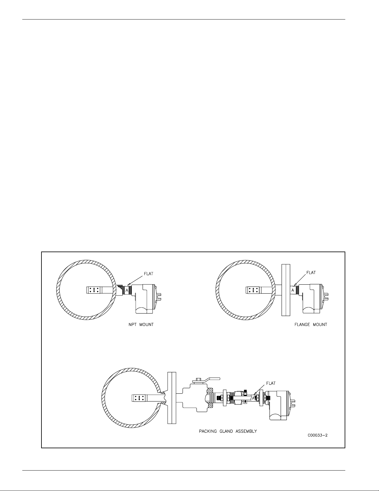
Flow Element Installation
Install the flow element in the process piping at the desired location. FCI recommends that the A side of the flow
element be placed so it is on the up-stream side of the normal flow direction. Verify that the flat area machined into
the flow element is flat, up and level. The flat is machined on the flow element near where it is screwed into the
enclosure. "FLAT UP & LEVEL" is also etched on the flat surface.
Threaded Mounting
Apply a lubricant/sealant compatible with the process to all threads. Use a pipe wrench for 1-1/4 inch (32mm) NPT
and larger connections (including exotic materials of construction), or an open-end wrench for 1-1/4 inch (32mm)
NPT and smaller connections. All connections should be tightened firmly. To avoid leaks, do not overtighten or
cross-thread connections. The figures in Appendix A and Figure 2-1, show this configuration.
Figure 2-1. Pipe, Flange and Packing Gland Assemblies
Model FR83 Flow Switch 2 - 2 Doc. No. 003147 Rev. B
Page 3

CHAPTER 2 - INSTALLATION FLUID COMPONENTS INTL
Flanged Mounting
As appropriate, use flange-face gaskets and sealants that are compatible with the process. Use the correct size
mounting bolts and tighten firmly. See Figures 2-1 and Appendix A for the mounting details.
Packing Gland Assembly
If used, the customer supplies a ball valve with the appropriate connection. Follow the threaded or flanged mounting
procedure as applicable.
Hand tighten the packing nut until the internal packing material is tight enough to prevent process media leakage, but
not enough to prevent the flow element shaft from sliding.
If used, open the valve. Check for process media leakage. Push or jack the flow element into the process pipe.
Tighten the packing nut 1/2 to 1 turn, torque to approximately 65 - 85 ft-lbs (88 to 115 N·m).
Rotate the split-ring locking collar to lineup with the connecting strap welded to the packing nut. Tighten two
1/4-28 hex socket cap screws on the split-ring locking collar. See Figures 2-1 and Appendix A for mounting details.
Control Circuit Installation
The standard configuration (see Appendix A, Figure A-7) of the instrument is with the control circuit already
installed in the local enclosure (the control circuit is physically mounted with the flow element). If the application
requires an optional remote operation (an operation where the control circuit is mounded separately from the flow
element), then continue with the following instructions.
Select a location for the remote enclosure within a 1000 feet (305 m) of the flow element. This location should be
easily accessible with enough room to open the remote enclosure. Secure the remote enclosure solidly to a vertical
surface capable of providing support. Use appropriate hardware to mount the remote enclosure. The outline
dimensions of a typical remote enclosure is shown in Appendix A.
Wiring Installation
Conduit Routing
All socket and/or terminal block connections are to be made through the 1 inch female NPT openings in the
enclosure(s). FCI strongly recommends that all electrical cables be run through an appropriate conduit for the
protection of the instrument and personnel.
Protection of the control circuit from moisture is an important consideration. Keep the entry of the conduit into the
enclosures in the downward direction so condensed moisture that collects in the conduit will not drain into the
enclosure. The local enclosure may be turned not more than 180° using the threads on the flow element stand pipe to
gain an acceptable orientation. In addition, FCI recommends sealing off the conduit with a potting Y or other sealing
method to prevent moisture from entering the enclosure.
Minimum Wire Size
Table 2-1 shows the smallest (maximum AWG number) copper wire that is to be used in the electrical cables used
for connecting the instrument to the customer alarms and power. Use a lower gauge of wire for less of a voltage
drop. Contact FCI concerning greater distances than those listed in the table.
Doc. No. 003147 Rev. B 2 - 3 Model RF83 Flow Switch
Page 4

FLUID COMPONENTS INTL CHAPTER 2 - INSTALLATION
Table 2-1. Interconnecting Cable Size (AWG)
Maximum Distance for AWG
Connection
10 ft.
(3m)
50 ft.
(15m)
100 ft.
(31m)
250 ft.
(76m)
500 ft.
152m)
1000 ft.
(305m)
AC Power 22 22 22 20 18 16
Relay (2A) 28 22 20 16 12 10
Relay (10A) 22 16 12 8 6
Flow Element Wires
for Remote Option*
24 24 24 22 22 18
Not
Recommended
*Requires a shielded cable which is connected to the control circuitry terminal
block.
Cable Connections
Caution:
In order to prevent circuit or component damage, remove the signal conditioner from the remote
enclosure (if present) prior to the pulling of conduit wire.
Note:
The installation of an AC line switch between the AC power source and the instrument is
recommended. This facilitates easy power disconnection and is an added safety feature.
Connect the cable wires per the applicable wiring diagram in Appendix A. Use the tag found on the instrument or
packing list to match the control circuit description with the modules that call out the wiring diagrams. The modules
are also found in Appendix A. The part of the tag description that denotes the control circuit is found between two
forward slashes (/......./) and starts with a circuit board name, e.g. /0018-...../. The code that follows corresponds to
the modules. The lack of a full code denotes that the control circuit has a standard configuration. Standard
configurations are denoted on the modules with the abbreviation STD.
The cable used to connect the flow element to the control circuit must be shielded. The shield drain wire is
terminated at the control circuit socket (terminal 7). The other end of the shield is left floating (no connection to the
terminal block). The standard cable provided has a shield and is 22 AWG wire.
Connect the relay outputs to the customer alarms. Also connect the power to the instrument power input. See
Appendix A for the appropriate connection information.
Model FR83 Flow Switch 2 - 4 Doc. No. 003147 Rev. B
 Loading...