

Page 1
CHAPTER 1 - GENERAL INFORMATION FLUID COMPONENTS INTL
1. General Information
Description
This document explains the operating principle of the Model RF83 Flow Switch. The following pages also present
the recommended procedures for the installation, operation, maintenance, and troubleshooting of the Model RF83.
The Model RF83 is an instrument that is capable of detecting bi-directional liquid or gaseous flow environments.
The instrument has field adjustable alarm set points for control of the media.
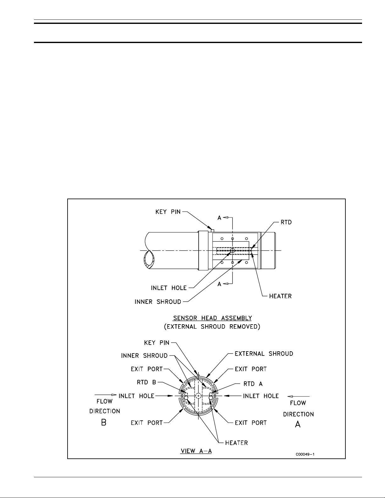
Flow Element
The operational parts of the flow element are the sensing points. The sensing points consist of four thermowells
(hollow tubes). There is two pair of thermowells welded together. The thermowell pairs have a heater in one
thermowell and a Resistance Temperature Detector (RTD) in the other thermowell. The thermowell pairs (sensing
points) are placed on opposite sides of a flow media barrier. There is a baffle placed around the sensing points to
direct the flow across the up-stream sensing point. As the flow media flows from sensing point B to sensing point A
(as shown in Figure 1-1) the flow media removes heat from the up-stream, heated RTD. There is no effect on the
heated RTD A. A delta R (DR) exists between the two RTD's that the electronics measures. If the flow reverses
RTD A looses heat and not RTD B.
Doc. No. 003147 Rev. B
Figure 1-1. Process Installation Showing the Sensing Point
1 - 1
Model RF83 Flow Switch
Page 2

FLUID COMPONENTS INTL CHAPTER 1 - GENERAL INFORMATION
Control Circuit
The basic functions of the control circuit are to provide power to the flow element, measure the DR between the two
RTDs, condition the sensing point signals, and provide relay alarm contacts for customer uses.
Single pole double throw (SPDT) or double pole double throw (DPDT) relays are available in the instrument for
connections to the customer alarm systems. The relay outputs can be set for either open or closed contacts when
there is either flow or no flow of the process media.
The place where the relays change state will vary depending on the type of media as well as air or liquid turbulence.
Therefore the instrument has field adjustable alarm set points.
Specifications
• Process Connections:
1 inch male NPT, 1-1/4 inch male NPT, or larger
flanged connections.
• Insertion Length:
2 inch (50mm) U-length, standard. Customer
specified U-length optional.
• Material of Construction:
All wetted surfaces are 316 series stainless steel with
nickel braze per process specifications AMS 4777.
Optional wetted surface material customer specified.
• Alarm Set Points:
Setable to any value within the indicated flow range.
5mV hysteresis. All units are preset with set-points
at mid-range in water. Factory certified alarm set
points available.
• Time Response:
5 to 150 seconds.
• Flow Rate:
From: 1 - 40 f/s (.3 - 12m/s) in air
To: .05 - .5 fps (.15 - 150 mm/s) in water.
• Electrical Connection:
• Relay Rating:
SPDT contacts rated at 6A at 115 Vac or 24 Vdc
resistive, relay coil de-energized at no-flow (standard
option). Optionalcontact and/or coil arrangements
are customer specified.
• Power Input:
100-132 Vac, 50/60 Hz, 6 watts maximum (standard
option). 24 Vac. 24 Vdc or 230 Vac are customer
specified.
• Electrical Enclosure:
Electrical components mounted in a NEMA 7 BCD
electrical enclosure. NEMA 4 and NEMA 4X
enclosures customer specified.
• Operating Temperatures:
Flow element: -100° to +350°F (-73° to +177°C).
Control circuit: -40° to +140°F (-40° to +60°C).
• Operating Pressure:
To 4000 psig (276 bar).
• Options:
Retractable probe and packing gland assemblies.
• Approvals:
1 inch female NPT
Model RF83 Flow Switch
1 - 2
FM, CSA, CENELEC, JIS and SAA for hazardous
locations.
Doc. No. 003147 Rev. B
 Loading...