

Page 1
OEM MASS FLOW METER: Configuration -2A1
Installation and Operation Guide
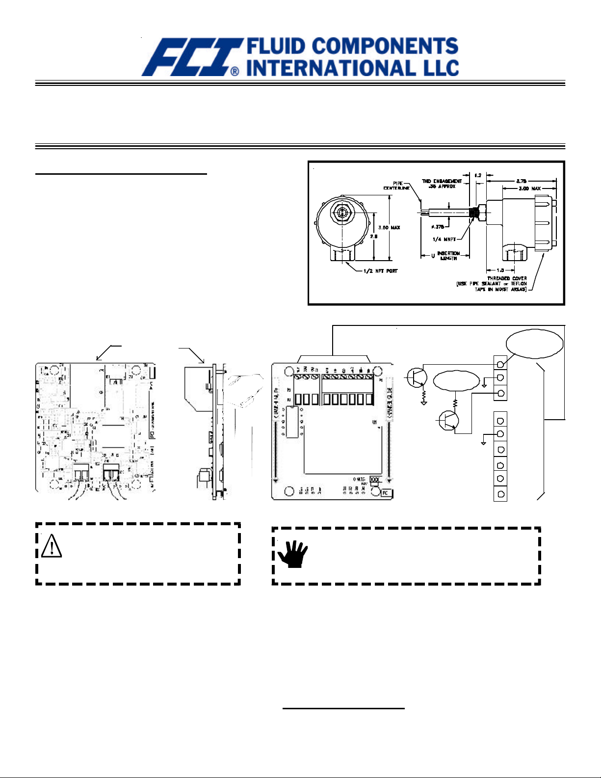
INSTRUMENT INSTALLATION
The OEM Mass Flow Meter is an insertion instrument capable of measuring air and gas flow in a wide range of processes. The instrument can be
top or side mounted. The process connection is male 1/4 inch NPT (or 1/2
inch NPT compression fitting). See the installation outline drawing below
for mounting dimensions.
There is an orientation mark etched onto the hexagonal surface of the
element. The flow element must be located with the orientation mark
parallel to flow. Apply an appropriate sealant to the male threads when
installing the flow element and securing enclosure cover. Tighten the
element until it is hand tight. Use a wrench to rotate the element until the
flow arrow on the hexagonal flat is in the direction and parallel to flow,
±2°. If possible, it is recommended the enclosure be located such that the
conduit port is in a downward direction to reduce the opportunitiy of
moisture collecting in the enclosure.
RJ11, (RS232
Connection)
Installation Outline Diagram
P2
Pulse or Alarm
15 VDC Output
50mA max
Pulse or Alarm
40 VDC max.
150mA max.
customer supplied
power source
SINK
COM
SOURCE
Reference Sensor
Active Sensor (RED)
Caution:
Only qualified personnel are to wire or test this
instrument. The operator assumes all
responsibilities for safe practices while wiring or
troubleshooting.
Use the following steps to wire the instrument:
l FCI recommends installing an input power disconnect switch
and fuse near the instrument to interrupt power during
installation, maintenance, calibration, alarm selection and
troubleshooting procedures.
l Ensure the power is off before wiring the instrument.
l Conduit or other protective sheathing should be connected to
the1/2 inch port of the enclosure.
l Unscrew and remove the top cover of the instrument. Lift
the circuit board assembly by pulling up on the white plastic pull
tie wrap. The customer connections are near the top of the
circuit board. Be careful not to stress the wires that are
connected to the circuit board.
VOUT
RET
4-20mA
Earth GND
VIN
+
VIN
P1
-
Instrument Wiring
Alert:
Use standard ESD (elctrostatic discharge) precautions
when handling the transmitter circuit board.
l Connect 24 VDC input power to P1 +V IN and -V IN.
l Connect the 4-20mA output terminals as required.
l Connect pulse or alarm output if desired (source or sink mode). Refer to
specifications and setup on following pages.
l Push the board back into the enclosure and replace the top cover.
l Turn power on to operate the instrument.
TROUBLESHOOTING
Verify that the wiring is correct. Contact FCI Technical Service if problems
still persist. The telephone number is (800) 854-1993, or (760) 744-6950.
This page is subject to proprietary rights statement on last page
Page 2

FLUID COMPONENTS INTERNATIONAL LLC OEM MASS FLOW
GENERAL SPECIFICATIONS
Material of Construction: Element; 300 Series Stainless Steel, Enclosure; Diecast Epoxy Coated Aluminum.
Operating Temperature: Flow Element; -40 to +250°F (-40 to +121°C)
Electronics; -40 to +140°F (-40 to +60°C)
Safety Proof Pressure: 500 psig.
Input Power: 9.5 to 36 Vdc, 3.5 watts nominal
Output Current: 4-20mA, 500 ohm maximum - scalable from 20:1 to 100:1 turndown of calibrated flow
Output Voltage: 0-10 VDC, 10K ohm minimum input impedance, directly related to temperature or flow
Output Pulse Source: Totalized flow or alarm set point. 15VDC. Pulse width at 50% duty cycle for rates 1 to 500Hz, 0.5
second pulse width for pulse rates below 1 Hz. 25mA maximum load pulsed , 10mA maximum load if state
set to normally on.
Output Pulse Sink: Totalized flow or alarm set point. Pulse width at 50% duty cycle for rates 1 to 500Hz, 0.5 second pulse
width for pulse rates below 1 Hz. Customer power source and load not to exceed 40VDC and 150mA.
Pulse Factor Setting: 0.001 to 1000 factor of full scale flow rate (not to exceed 500 Hz). Default = 1.
Pulse Sample Period: 0.5 to 5.0 seconds. Default = 1 second
Alarm set point hysteresis 2% of set point
Repeatability: 0.5% of reading
Mounting: Vertical or horizontal
Service: Air or gas (depends on calibration)
Flow Range: .25 to 800 SFS (depends on calibration)
Enclosure Classification: UL Class 1 and 2, Div 1 & 2, Groups C, D, E, F, G
Approvals: CE Mark
Configuration options:
4-20mA out: Mass Flow/Volumetric Flow or Temperature
0-10V out: Mass Flow/Volumetric Flow or Temperature (default temperature output range is -40 to 250°F [-40 to 121°C]).
Source out: Pulse (totalizer), or Alarm Function (set-point). Pulse out factorable from 0.001 to 1000 of set flow units, high or low state.*
Sink out: Pulse (totalizer), or Alarm Function (set-point). Pulse out factorable from 0.001 to 1000 of set flow units, high or low state.*
* Default pulse factor is set to 1. For example, if meter is configured in SCFM, then each pulse out will represent 1 SCF. Maximum frequency of
pulse output is 500Hz., therefore, pulse factor must not be set to levels that will exceed this level at maximum flow. i.e. if max. flow = 100 SCFM, @
pulse factor (PF) = 1, pulse rate = 1.667 Hz. @ PF 0.1 = 16.67 Hz, @ PF 0.01 = 166.7 Hz. However, pulse factor 0.001 results in 1667 Hz -- which
exceeds limit of 500 Hz. The pulse sample period is the period for updating the accumalated flow from the internal totalizer. Pulses are output
within this period at a frequency calculated based on the pulse factor setting. In-between pulses are saved and output in the next cycle (pulses are
never lost). The pulse output signals can be independently configured to change from “high” to “low” state or “low” to “high” state. See Table 4.
Setup Interface
All parameters on this meter are set through the RS232 interface connection (RJ11 plug). An FCI model FC88 handheld calibrator or direct
computer interface may be used to access these parameters. The FC88 is powered through the meter and comes with the serial interface cable. If a
computer interface is used, an adapter cable (RJ11 to 9 pin Computer Serial Port) is required and may be obtained from FCI: Part No. 014108-02.
Using Windows Terminal (usually located in Accessories) execute the program by double-clicking on the Terminal Icon.
1. Go to Settings. 2. Click on Communication.
3. Set for COM1 or COM2, 9600 Baud, 8 Bit, and No Parity. Press OK 4. Press the ENTER key to see the Input Mode? prompt.
5. Enter any of the Meters single letter commands to execute a function (reference function menu on following page).
Menu Control and Organization
Most entries require at least two key strokes; a Capital letter and the [ENTER] key, or one or more numbers and the [ENTER] key. All
user entries begin at the Input Mode?< prompt except when the instrument is in the Main Function Mode (just press the desired
function letter and [ENTER] to make an entry).
A user entry is indicated by brackets [ ] being placed around the entry. Y/N refers to Yes (Y), save or change parameter or No (N) do
not save or change parameter unless otherwise specified. Backspaces are made using the backspace [BKSP] key. Some entries are
case sensitive between numbers and letters. Be sure the SHIFT key is pressed to indicate the correct case. A square after the prompt
caret indicates the FC88 is in lower case. A slightly raised rectangle in the same spot indicates the FC88 is in the upper case.
It is recommended that the FC88 be plugged into the instrument before power is applied. If the FC88 is plugged in while the
instrument power is on and the FC88 does not respond, press [ENTER], if there is no response press [P], if there is still no response
Press [N].
Note: The Zero and Span may be changed from the original calibration, provided new values are within the original calibrated range. i.e. if original
calibration was 1 to 100 SCFM (4-20mA), new zero must be equal or greater than 1 SCFM, new span must be equal or less than 100 SCFM.
Some entries require a Factory pass code (Contact FCI Field Service) to continue programming the instrument. The instrument will
prompt the user when this is necessary. Do not change any parameters that require this code unless there is an absolute understanding
of the instrument's operation. The user can not exit some routines unless all entries are completed or the power is recycled.
This page is subject to proprietary rights statement on last page
Doc. No. 06EN003329 Rev. B
Page 3

OEM MASS FLOW FLUID COMPONENTS INTERNATIONAL LLC
The top level of the menu is shown below. Enter the large letter in the tables below to activate a command.
Table 1
Table 2
Customer Settings
T Normal Operation Mode
All outputs active
F K Factor (1 is default)
Z Flow Units Set-up
Select flow units (4 English, 4 Metric),
Pipe diameter and span/zero settings
W Totalizer Mode
Disable/Enable internal totalizer
V Output Configuration Selection
Select one of four output configurations: pulse
and/or alarm, plus pulse factor and/or set point
N Warm Reset
Re-initialize instrument without removing power
Table 3
“Z” Flow Units Set-up and Scaling
Units
Select E=English M=Metric
Select F= SFPS M=SMPS
or C = SCFM N = NCMH
or H = SCFH O = NCMM
or L = LBS/H K = KG/H
For Volumetric or Mass Flow
Select R = Round pipe or duct
or S = Square duct
Set Diameter or Wide X High (in inches or mm)
Set Max = Maximum flow rate (span)
Set Zero = Minimum flow rate (zero)
Note: Changing units requires rescaling the unit (set new zero and span).
Analog out
Output Mode
Selected
4-20mA: Flow
0-10V: Temp
Change? (Y/N)>
4-20mA: Flow
0-10V: Temp
4-20mA: Flow
0-10V: Flow
4-20mA: Temp
0-10V: Flow
4-20mA: Temp
0-10V: Temp
Display comes up to last setting saved
and stays for 2 seconds.
If N or [ENTER], proceed to Pulse out.
If Y, display moves to selection
options and asks for confirmation. If
you miss the option, select [Enter]
repeatedly to loop around.
Enter 1 to make
the selection__
Enter 2 to make
the selection__
Enter 3 to make
the selection__
Enter 4 to make
the selection__
Diagnostics and Factory Settings
C Calibration Information
Display only: A/D, Delta-R, Ref-R data values
D Diagnostics
Display only: Check-out of functional conditions
K Factory Calibration Settings
Display only: Cal. parameters, i.e. linearization
and temperature compensation coefficients.
L Calibrate Outputs Factory Access Only
Y Command Line Interface Factory Access Only
R Factory Reset
Replaces user data with factory calibration data
User may exit command at any time entering
“Q” [ENTER] in menus: D, K, L, V, W, or Z.
Table 4
“V” Output Configuration Set-up
Analog out
Select 1 2 3 4
4-20mA out Flow Flow Temp Temp
0-10 Vout Temp Flow Flow Temp
Pulse out
Select 1 2 3 4
Source out Pulse Pulse Alarm0 Alarm0
Set Factor Factor Set pt.0 Set pt.0
Set Period Period State0 State0
Set State0 State0
Sink Pulse Alarm1 Pulse Alarm1
Set Set pt.1 Factor Set pt.1
Set State1 State1 Period State1
State1
Pulse out
Pulse Out
Selected
Source: Pulse
Sink: Pulse
Change? (Y/N)>
Source: Pulse
Sink: Pulse
Enter 1 to make
the selection #__
Source: Pulse
Sink: Alarm1
Enter 2 to make
the selection #__
Source: Alarm0
Sink: Pulse
Enter 3 to make
the selection #__
Source: Alarm0
Sink: Alarm1
Enter 4 to make
the selection #__
PFactor: 1.000
Change? (Y/N)>
if yes
Enter new factor: ____
Sample Period: 1 second
Change? (Y/N)>
if yes
Enter new Sample Period: ____
If alarm is a selected output
Set point1: 000 Set points are in the
same units as the flow
or temp.
Change? (Y/N)>
if yes
Enter new set point: ____
Resume normal operation
Source state: 0
Change to 1?>
Sink state: 1
Change to 0?>
This page is subject to proprietary rights statement on last page
Doc. No. 06EN003329 Rev. B
Page 4

FLUID COMPONENTS INTERNATIONAL LLC OEM MASS FLOW
General Navigation Note: Pressing [Y] [ENTER] acknowledges a change to the existing setting or toggles the
current setting. Pressing [ENTER] alone, moves to the next menu item.
Example: COMMAND Z (Reference Table 3)
Case: Volume (English) in SCFM, Round pipe
Pressing [Z] [ENTER] will display “E for English or ” followed by “M for Metric.” Press an [E] [ENTER].
The next prompt is 0=SFPS, 1=SCFM
2=SCFH, 2=LBS/H# Press [1] [ENTER].
The next prompt is “R round duct or ” followed by “S rectangular <.” Press [R] [ENTER].
The next prompt is “Diameter: inches ” “x.xxxxxx” followed by “Change it ?<.” Press [Y] [ENTER].
Enter a new value or else press [N] [ENTER] or [ENTER].
The next prompt is “Max = xxx.xxxxxx” followed by “Change F.S.?<.” Press [Y] [ENTER]
Enter a new value or else press [N] [ENTER] or [ENTER].
The next prompt is “Zero = x.xxxxxx” followed by “Change it ?<.” Press [Y] [ENTER]
Enter a new value or else press [N] [ENTER] or [ENTER].
The last prompt is “Input mode ?<.”
Enter “T” to resume normal operation.”
Note: The output may be scaled anywhere between 10:1 to 100:1 of original factory calibration.
Example: COMMAND V (Reference Table 4)
Case: 4-20mA = flow, 0-10V = Temperature, Source Out = Pulse, Sink = Alarm
Pressing [V] [ENTER] will display “Output Mode Selected” followed by:
“4-20mA = Flow” “ 0-10V = Temp” followed by
“Change? (Y/N)”
Press [ENTER] (no change).
The last saved mode will display at this point. i.e.,
“Source: Pulse” “Sink: Pulse” followed by,
“Change? (Y/N)” Select Y [Enter]. The display reads,
“Source: Pulse” “Sink: Pulse” followed by,
“Enter 1 to make the selction #.” Select [ENTER]. The next display reads,
“Source: Pulse” “Sink: Alarm” followed by,
“Enter 2 to make the selction #.” Select 2 and [ENTER]. The next prompt reads,
“PFactor: 1.000” “Change? (Y/N)>” (this factor can be anywhere from 0.001 to 1000 - Refer to Configuration
options on page two for definition of factor). If no change, select N and/or [ENTER] to continue. The next prompt is,
“Sample Period” “Change? (Y/N)>” (this value may be set from 0.5 to 5 seconds - Refer to Configuration options
on page two for definition of sample period). If no change, select N and/or [ENTER] to continue. The next prompt is,
“Source state: 1” “Change to 0?>” (this selection toggles the pulse signal normally high or normally low).
[ENTER] to read display.
“Switchpt1” “0.0000000” the current set point.
“Change? (Y/N)>” enter Y [ENTER] and enter #______ . Set Point Value , i.e. 50 (value is in same units as the flow and
must be within the calibrated range). [ENTER]. The next prompt is,
“Sink state: 1” “Change to 0?>” . Set the output signal to be normally “High” or normally “Low.” Pressing [Y]
[ENTER] toggles the current setting. Pressing [ENTER] resumes normal operation.
Notice of Proprietary Rights
This document contains confidential technical data, including trade secrets and proprietary information which is the property of Fluid Components
International LLC (FCI). Disclosure of this data to you is expressly conditioned upon your assent that its use is limited to use within your company only
(and does not include manufacture or processing uses). Any other use is strictly prohibited without the prior written consent of FCI.
Visit FCI on the Worldwide Web: www.fluidcomponents.com
1755 La Costa Meadows Drive, San Marcos, California 92078 USA - 760-744-6950 - 800-854-1993 - Fax 760-736-6250
Doc. No. 06EN003329 Rev. BFluid Components International LLC (FCI) All Rights Reserved
 Loading...