

Page 1

CHAPTER 3 - OPERATION FLUID COMPONENTS INTL
3. Operation
Caution:
Introduction
The flowmeter has been configured and calibrated to customer specifications. Each flowmeter contains distinct
operating limits and units of measurement. This chapter will show how to determine and manipulate the
configuration of the flowmeter.
Start Up
Verify the wiring before applying power. Also verify the correct power connections have been made to the flow
transmitter.
1. Apply Power.
2. Wait 5 minutes for the unit to warm-up and stabilize.
3. The flowmeter evaluates sensing points as out-of-range until they have warmed up to operating temperature.
The flow transmitter contains electrostatic discharge (ESD) sensitive devices. Use standard ESD
precautions when handling the flow transmitter. See Chapter 2, Installation for ESD details.
The flowmeter displays a system status message of "Check Heads" until all sensing points are functioning
within their calibrated range. This status message should change to the normal display of "System OK" within
the 5 minute warm-up period. The output signal displayed should be representative of the estimated or
calculated current process media flow.
4. The unit automatically enters the flow metering mode and the display sets to normal operation.
The flowmeter outputs should now indicate the mass flow rate in the desired units of measure.
In the event that the display or the "System OK" message does not appear, or the values are out-of-range or
obviously incorrect, then turn the power off and proceed to Chapter 5 - Troubleshooting.
Using the MT91 Software with Display
Display
The flowmeter contains a 4 x 20 character LCD display. Flow rate, temperature, and system status are all accessible
through the display.
Menu Window
Four components make up the menu window. They are the menu level, title, selections, and prompt line. These
components are illustrated in Figure 3-1. The top line displays a menu level and title. Lines two and three are used
to scroll through available options. The prompt line indicates which menu commands are appropriate.
2.1.1 FLOW
1=Velocity
2=Volume
Menu Code
N=MORE UP HOME
Title
Available Selections
Prompt Line
C00219-1
Figure 3-1. The Menu Window
Doc. No. 003185 Rev. B 3 - 1
Model MT91 Multipoint Flowmeter
Page 2

FLUID COMPONENTS INTL CHAPTER 3 - OPERATION
The menu level is a numeric reference which identifies each window of the menu structure. The menu level in
Figure 3-1 indicates that the user is three levels deep (Level 2, sublevel 1, sub-sub-level 1). This example code can
be associated functionally as 2(SETUP).1(DISPLAY).1(FLOW). Occasionally, the depth of the menu makes
displaying the complete menu level impractical. When this happens, the special character “>” indicates that the
menu level may be deeper than the code indicates (e.g. “2.2.3.1>RLY[1] MODE” ).
The title gives the user a better idea of where the system is within the menu structure. Some titles are informative
enough to completely describe the menu function, while other titles are ambiguous unless the parent menus are
known.
Other Window Types
Another common window encountered is a non-scrolling menu. The window is similar to the menu window except
that does not scroll and all choices are contained within the window. The current selection (if there is one) is also
contained in the parenthesis to the left of the question mark.
Menu Control
The prompt line and available selections display key strokes for that menu level. If a key is pressed that is not valid
for that menu, the screen will stay the same. The key pad layout is shown in Figure 3-2.
0-9 Enter numbers
Y Yes to prompts
1 2 3 Y N
4 5 6
7 8 9 P
ENTR
0 #
_
HOME
.
UP
C00220-1
N No to prompts; more display
- minus sign
. decimal point
←
P no special use
ENTR accepts current value
HOME return to main menu
UP backup one menu level
backspace
Figure 3-2. Keypad Layout
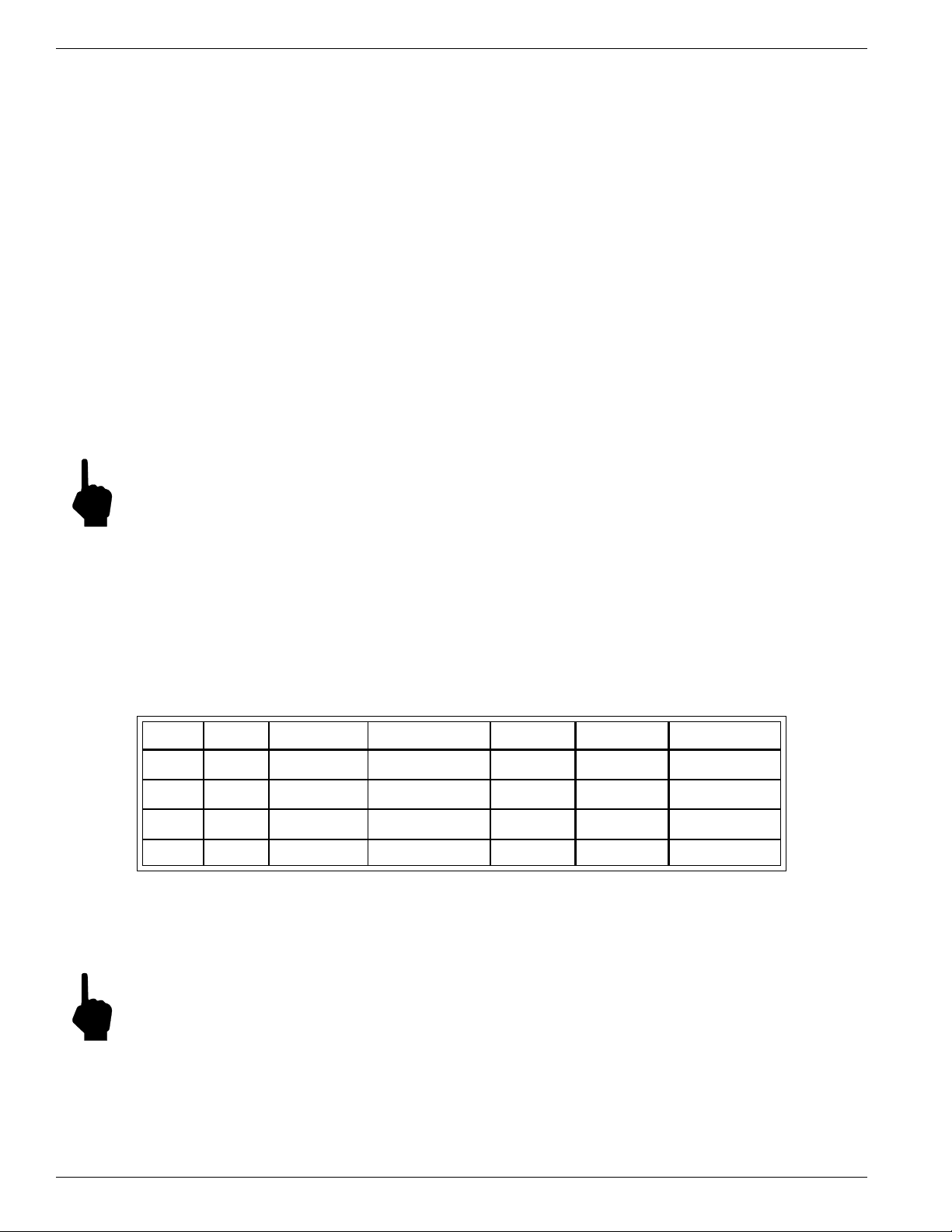
Table 3-1. Key Functions
See Table 3-1 for key pad assignments. At any time, press the HOME key to display the main menu.
HOME can be used to escape from calibration routines, restart a progression into the menu structure, or
quickly change from one area of the menu to another.
When N=MORE is displayed on the prompt line, more than two menu selections are available. Press N to
scroll through all the selections.
When UP is displayed on the prompt line, the UP key can be used to back out of menus. The menu moves
back one level each time the UP key is pressed.
To make a selection, press the numeric key associated with the desired menu selection. The selection does
not have to be displayed, but it must be one of the available selections.
Every path through the menu will eventually cause control to pass from the menu structure to a routine that
performs a task such as change a parameter value, initiate a test, or calibrate the system hardware. Some of
these routines still provide selections that emulate the menu structure. When the system is operating outside
the menu structure, there are subtle differences in the user interface. For example, the UP key may have no
affect or the prompt line won't appear.
Menu Organization
The top level of the menu is shown in Figure 3-3. The menu structure is divided into four major groups, a
display function, and the revision display.
Model MT91 Multipoint Flowmeter
3 - 2 Doc. No. 003185 Rev. B
Page 3

CHAPTER 3 - OPERATION FLUID COMPONENTS INTL
• The first menu option places the units display into the normal display mode. When the system is in this mode,
flow and/or temperature measurements are displayed. While in the normal display mode, pressing any key will
cause the main menu to display.
• The Setup group presents the options for customizing the system inputs and outputs. Most of the settings will
be made through menus in this group.
• The diagnostics group provides displays that help isolate problems and test the system integrity.
• The calibration group is used primarily by factory technicians, but there are displays that can be helpful to the
customer.
• The verify group provides a means to view the values of important system parameters.
• Finally, the firmware version is available for display.
0.0 MAIN MENU
1=Normal Display
2=Setup
3=Diagnostics
4=Calibration
5=Verify
6=Version
7=Time Delay
Normal Display
CH1: 47.8 SF/S
CH2: 89.2 F
K1 K2
System OK
2.0 SETUP
1=Display
2=Outputs
3=Communications
4=Configuration
5=Password
6=Clock
3.0 DIAGNOSTICS
1=System Status
2=Output Tests
3=Calibration Tests
4=Schedule Tests
4.0 CALIBRATION
1=Cal Initialize
2=Cal Inputs
3=Cal Outputs
4=Cal Flow
5.0 VERIFY
1=Verify Setup
2=Verify Cal
Version x.xx
Release Date
dd-mm-yy
2.1 DISPLAY
1=Flow
2=Temperature
3=Screen Setup
2.2 OUTPUTS
1=Assign Heads
2=Analog
3=Relays
4=Filter
5=Corrections
2.3 COMMUNICATIONS
1=Mode
2=Baud
3=Protocal
4=RS-485 Address
2.4 CONFIGURATION
1=Setup User Config
2=Setup Factory Cfg
3=Save Config
2.5 PASSWORD
1=Change User PW
2=Enable PW
2.6 SET CLOCK
1=Set Clock
2=Auto Offset
5.1 VERIFY SETUP
1=Flow
2=Temp
3=Outputs
4=Communication
5.2 VERIFY CAL
1=Inputs
2=Outputs
3=Flow
3.1 SYSTEM STATUS
1=Sensors
2=Heaters
3.2 OUTPUT TESTS
1=Analog Output Test
2=Relay Test
3.3 CALIBRATION
TESTS
1=Start Test
2=Display Results
3.4 SCHEDULE TESTS
1=Calibration Drift
2=Enable Auto Test
4.1 CAL INITIALIZE
1=All Cal Parms
2=Input Cal Parms
3=Output Cal Parms
4=Flow Cal Parms
5=Misc Cal Parms
4.2 CAL INPUTS
1=Sensor Type
2=Excitation
3=Heaters
4=Normalize to R
5=Unipolar rR & dR
6=Bipolar rR & dR
7=Display dV &dV
4.3 CAL OUTPUTS
1=Analog Outputs
7.0 TIME DELAY
Enter Minutes:
(1)
?
7.0 TIME DELAY
Output Frozen
Press any key to stop
Time Left: 0:07
Figure 3-3 Menu Flowchart
Doc. No. 003185 Rev. B 3 - 3
4.4 CAL FLOW
1=Coefficients
2=Limits
3=Temp Comp
4=Offset
C00221-1.vsd
Model MT91 Multipoint Flowmeter
Page 4

FLUID COMPONENTS INTL CHAPTER 3 - OPERATION
Quick Custom Setup
In order to use the quick operation procedure, an assumption has been made that the password is enabled (this is the
factory preset condition).
If mistakes in data entry are made, press the back arrow key to correct mistake.
Menu level refers to the sequence of key to press to reach a particular function from the MAIN MENU. For
example, to go to menu level 2.2.1, press HOME, 2, 2, and 1.
Y/N refers to Y Save Permanently or Change Parameter or N Do Not Save Permanently or Do Not Change
Parameter.
Using Main Functions
MAIN MENU Press HOME.
Returns user to MAIN MENU. In some cases, it may be necessary to press
HOME more than once.
NORMAL DISPLAY menu level 1.
To view the NORMAL DISPLAY
DelR and RefR menu level 4.2.5
To view a sensing point's raw signal DelR and RefR. When prompted, enter
the number of the sensing point to be viewed.
PASSWORD menu level 2.5.1.2
Enable or Disable the PASSWORD
PASSWORD menu level 2.5.1.1
Change the user PASSWORD. If the password protection is enabled, the
user must enter the current password.
Selecting Units of Measurement
After reaching the menu level, select the combination of units that will produce the desired end result.
Velocity units menu level 2.1.1.1
Length 1=FT, 2=M and
Time 1=Sec, 2=Min, 3=Hrs, 4=Day
Volume units menu level 2.1.1.2
Volume 1=SCF, 2=NCM, 3=NLP
Area 1=Square Feet, 2=Square Meters
Area Value enter the area of the duct
Time 1=Sec, 2=Min, 3=Hrs, 4=Day
Mass units menu level 2.1.1.3
Mass 1=LBM, 2=KG, 3=TON, 4=TONNE
Area 1=Square Feet, 2=Square Meters
Area Value enter the area of the duct
Time 1=Sec, 2=Min, 3=Hrs, 4=Day
Temperature units menu level 2.1.2
Model MT91 Multipoint Flowmeter
1=°F 2=°C 3=K 4=°R
3 - 4 Doc. No. 003185 Rev. B
Page 5

CHAPTER 3 - OPERATION FLUID COMPONENTS INTL
Setting Up Analog Outputs
Sensing Point Outputs menu level 2.2.1
Channel 1=Chan 1 2=Chan 2
After selecting a channel, the menu automatically provides new
selections to assign sensing points.
Sensing Points 1=Add All Heads 2=Add Head 3=Del All Heads
4=Del Head 5=View Assigned 6=Save
An "X" will mark on the display to show which sensing points are assigned
to the selected channel. To keep changes, user must save assignments.
Output Parameters menu level 2.2.2
Channel 1=Chan 1 2=Chan 2
After selecting a channel, the menu automatically provides new
selections to set output parameters.
Output Signal* 1=0-5V 2=0-10V 3=4-20mA
Mode 1=Flow 2=Temp
Full Scale enter a value
Port Zero enter a value
*Set Jumpers to match. See Chapter 2.
Setting Up Relays
Relays 1 and 2 can be set as switch points or test/status parameters. If relays 1 or 2 are used for switch
points, their mode must correspond to their respective analog output channels. (e.g. If relay 1 is set to
be a flow switch point, then analog output channel 1 must be in the flow mode.) If relays 1 or 2 are set
to flow or temperature modes, the user MUST set switch point and hysteresis parameters. If this is not
done, a chattering noise will be heard. Relay 3 and 4 can only be set as test/status parameters.
Relay Mode menu level 2.2.3.1
Relay 1=Rly #1 2=Rly #2 3=Rly #3 4=Rly #4
After selecting a relay, the menu automatically provides new
parameters to set the mode.
1=View Mode 2=Flow 3=Temperature
4=System Status 5=Zero Test 6= Span Test.
Switch Points menu level 2.2.3.2
Relay 1=Rly #1 2=Rly #2 3=Rly #3 4=Rly #4
After selecting a relay, the menu automatically provides new
parameters to set the switch point.
1=View Sw. Pt. 2=Above 3=Below
4=Inside 5=Outside
Hysteresis menu level 2.2.3.3
Relay 1=Rly #1 2=Rly #2 3=Rly #3 4=Rly #4
Doc. No. 003185 Rev. B 3 - 5
Model MT91 Multipoint Flowmeter
Page 6

FLUID COMPONENTS INTL CHAPTER 3 - OPERATION
In-Depth Custom Setup Procedure
When a flowmeter leaves the factory, it is configured to the application information know at the time of order. At
installation time; however, changes to the factory settings may be necessary. There are several parameters that can
be modified to customize the system. This section describes how to customize the flowmeter.
Menu level refers to the sequence of key to press to reach a particular function from the MAIN MENU. For
example, to go to menu level 2.2.1, press HOME, 2, 2, and 1.
Each time a system parameter is changed, the display will prompt the user to save the change. For the change to
endure through power off periods or a system reset, press Y. For a temporary change, press N. When changes are
not saved, the user can restore the previous settings by cycling the input power or pressing any key for more than 10
seconds to reset the system.
In most cases, the existing value of the parameter that is changing will be displayed. If no change is required, press
ENTR, select it again, or press HOME.
Since the flowmeter has multiple inputs and outputs, some parameters are stored in groups. For example, the analog
output parameters apply to both channels one and two. The menu level to change the analog output parameters will
prompt the user to select a channel. After making changes to that channel, back out of and re-enter the menu level to
make changes to the other channels. Use either the UP key or the HOME key to back out of the menu level.
Password Protection
Before customizing the flowmeter configuration, the customer must have access to the system parameters. Two
levels of password protection affect access to these parameters.
Factory Level
The highest level of protection requires a factory password for access. This password prevents inadvertent changes
to variables associated with the system calibration, sensing point type, and other parameters that require factory
resources to properly set.
User Level
The second level of protection requires a user password for access. This password provides the customer with the
ability to limit access to parameters that affect the way the system operates.
Both levels of password protection can be enabled or disabled. When the system leaves the factory, the factory level
protection will be enabled and the user level will be left disabled. No password is required to enable a level of
protection, but the appropriate password is required to disable protection.
Note:
The user password is set to “123” when the system is shipped.
Ø To edit the user password
1. Go to menu level 2.5.1 (SetupÞ PasswordÞ Change User PW).
2. If current user password if it is enabled, enter the current password, then press ENTR.
3. Enter desired password, then press ENTR.
Ø To enable and disable user password protection
1. Go to menu level 2.5.2 (SetupÞ PasswordÞ Enable PW).
2. If user password is already enabled, enter password. Select 2=Disable to disable password.
3. If user password is not enabled, select 1=Enable to enable the password.
Model MT91 Multipoint Flowmeter
3 - 6 Doc. No. 003185 Rev. B
Page 7

CHAPTER 3 - OPERATION FLUID COMPONENTS INTL
Selecting Units of Measure
Internally, the unit will always work in units of standard feet per second (SF/S) and degrees Fahrenheit (°F). The
user can choose from several types of units for display and output scaling. Table 3-2 shows the units of measure and
their abbreviations for temperature and flow.
Table 3-2. Units of Measure and Abbreviations
Temperature Length* Volume* Mass Time
Fahrenheit (°F) feet (SF) cubic feet (SCF) pounds mass (LB) seconds (S)
Celsius (°C) meters (NM) cubic meters (NCM) kilograms (KG) minutes (M)
Kelvin (K) liters (NLP) English ton (TON) hours (H)
Rankine (°R) metric tonnes (TONNE) days (D)
*Length and Volume units are based on FCI standard conditions (70°F and 14.7 PSIA); therefore,
the units are preceded with an S.
A sequence of selections is required to set a new unit of measure for flow. At each step through this process, the
existing unit will be displayed, even if it’s undefined, and the user will be prompted to change it. Only Y or N will be
acceptable responses to the prompts. To properly set new units, complete the menu entries until the new flow unit is
displayed. If the change is only temporary, don’t save any settings during the process.
Note:
If only some of the settings in this process are saved, the units of measure may be incorrect after a system
reset or power up.
The output may not conform to the units displayed if after partially completing the selection of new units,
HOME or the hardware reset are used to exit the process.
Ø To set a new unit of measure for flow rate:
1. Go to menu level 2.1.1 (SetupÞ DisplayÞ Flow). Select from the following three options: 1 Velocity,
2=Volume, or 3=Mass and then follow the corresponding procedure below.
w To set velocity units:
2. Select 1=Velocity.
3. The program will prompt the user to change the units of length first. Select from the following units: 1=Feet or
2=Meters.
4. The program will prompt the user to change the units of time next. Select from the following units: 1=Seconds,
2=Minutes, 3=Hours, 4=Day. The units of velocity will display, press any key to exit to menu level 2.1.1.
w To set volume units:
2. Select 2=Volume.
3. The program will prompt the user to change the units of volume first. Select from the following units:
1=SCF - standard cubic feet, 2=NCM - normal cubic meters, or 3=NLP - normal liter per.
4. The program will prompt the user to change the units of area. Select from the following units: 1=Square Feet or
2=Square Meters.
5. The user will be prompted to change the value of the area. Enter a numeric value for the area.
6. The user will be prompted to change the units of time. Select from the following units: 1=Seconds, 2=Minutes,
3=Hours, or 4=Day. The selected units of volume will display, press any key to exit to menu level 2.1.1.
Doc. No. 003185 Rev. B 3 - 7
Model MT91 Multipoint Flowmeter
Page 8

FLUID COMPONENTS INTL CHAPTER 3 - OPERATION
w To set mass units:
2. Select 3=Mass.
3. The user will be prompted to change the units of mass first. Select from the following units:
1=LBM - pounds mass, 2=KG - kilograms, 3=TON - English ton, or 4=TONNE - metric ton.
4. The user will be prompted to change the units of area. Select from the following units:
1=Square Feet or 2=Square Meters.
5. The user will be prompted to change the value of area. Enter numeric value for area.
6. The user will be prompted to change the units of time. Select from the following units: 1=Seconds, 2=Minutes,
3=Hours, 4=Day. The units of mass will display, press any key to exit to menu level 2.1.1.
Ø To set a new unit of measure for temperature:
1. Go to menu level 2.1.2 (SetupÞ DisplayÞ Temperature).
2. Select from the following units: 1=°F - degrees Fahrenheit, 2=°C - degrees centigrade, 3=K - Kelvin, or
4=°R - degrees Rankine.
Selecting the Normal Display Screen
There are two formats for displaying flow information. These formats are referred to as screen 1, and screen 2.
Figure 3-4 shows an example of both screens.
CH1: 21320 LB/H
CH2: 96.2F
K1 K2
SYSTEM OK
Sensor[1]=65.4SF/S
Sensor[2]=63.2SF/S
Sensor[3]=66.0SF/S
Sensor[4]=65.2SF/S
Screen 1 Screen 2
C00222-1
Figure 3-4. Normal Display Screen 1 and Screen 2
Screen 1 provides numeric output for the two analog channels.
Screen 2 provides for the display of velocity at four points simultaneously. Many systems use only four points. This
display is useful when comparing the instrument with a Pitot traverse, or observing the flow profile.
Ø To select screen 1 or 2:
1. Go to menu level 2.1.3 (SetupÞ DisplayÞ Screen Setup).
2. Select from the following options: 1=Screen 1 or 2=Screen 2.
Assigning Sensing Points to Outputs
The first step to processing a sensing point input is to assign the sensing point to an output channel. There are two
channels in the flowmeter. Assign any combination of one to sixteen sensing points signals to either or both
channels.
Ø To assign sensing points to outputs:
1. Go to menu level 2.2.1 (SetupÞ OutputsÞ Assign Heads).
2. Select output channel, 1=Chan 1 or 2=Chan 2.
3. Select from the following options:
1=Add All Heads - this will assign all sensing points to the selected output channel;
2=Add Head - this will assign one sensing point at a time, the user can enter up to 16 different sensing points;
3=Del All Heads - this is used to clear all assigned sensing points from the selected channel;
4=Del Head - this is used to delete one sensing point at a time; or
5=View Assigned - the user can view the current sensing points assigned to the selected channel for 2 seconds.
Model MT91 Multipoint Flowmeter
3 - 8 Doc. No. 003185 Rev. B
Page 9

CHAPTER 3 - OPERATION FLUID COMPONENTS INTL
2.2.1 CHAN 1 HEADS
1 . . . 5 . . . . 0 . . . . 5 .
x x x x . . . . . . . . . . . . .
Enter Head #?
C00223-1
Figure 3-5 Assign Heads Displays
4. Figure 3-5 shows the display when adding or deleting heads. The ‘x’ signifies a selected head. To add or delete
a head, enter the number of the head, then press ENTR. When finished, press ENTR again without an entry.
5. Select 6=Save to ensure survival of the changes through resets and power cycles.
Setting Analog Outputs
The analog output channels are defined by four parameters: zero, minimum flow, maximum flow, and full scale.
Figure 3-6 shows how these parameters affect the output.
Figure 3-6. Analog Output
Full scale represents the flow or temperature value that corresponds with the maximum output signal.
Zero represents the flow or temperature value that corresponds with the minimum signal output. Minimum signal
output can be set to indicate a flow of zero. This is often referred to as a zero-based signal output. A minimum
signal that represents a value greater than zero is referred to as non-zero based.
Minimum and maximum flow are factory set parameters that do not appear as options in this menu level. Until the
minimum flow value is reached, the output will remain at the zero level. Once the minimum flow threshold is met or
exceeded, the output signal will jump to the value determined by the zero and full scale settings.
Output signal is physically selected with a jumper setting as described in Chapter 2. 0-5 Vdc, 0-10 Vdc and 4-20
mA are the available options.
Mode defines the channel as a flow or temperature output.
Ø To set analog outputs:
1. Go to menu level 2.2.2 (SetupÞ DisplayÞ Analog). Select 1=Chan 1 or 2=Chan 2.
2. Select 1=Output Signal. Then select from the following options: 1=0-5V, 2=0-10V, or 3=4-20mA.
3. Select 2=Mode. Then select from the following options: 1=Flow or 2=Temp.
4. Select 3=Full Scale. Enter a numeric value, then press ENTR to accept it.
5. Select 4=Port Zero. Enter a numeric value, then press ENTR to accept it.
Note:
If a different output signal is selected other than the factory calibrated output, a re-calibration of the analog
output board will be necessary. See following procedure. Ensure that the corresponding jumper is placed
in the correct position. See Chapter 2 for jumper positions.
Doc. No. 003185 Rev. B 3 - 9
Model MT91 Multipoint Flowmeter
Page 10
FLUID COMPONENTS INTL CHAPTER 3 - OPERATION
Ø To calibrate the analog output boards:
The analog output board calibration parameters are saved on the controller board. Therefore, analog output boards
are not interchangeable.
Tools needed:
DVM (4 1/2 digit minimum)
Calibrated 250W resistor
1. Turn off the power to the flowmeter.
2. Set both jumpers on the analog output board to the output type selected above.
3. Connect a DVM to the appropriate connection of the analog output board. Use a precision 250ohm resistor if
the output is 4 to 20mA.
4. Apply power to the flowmeter.
5. Go to menu level 2.2.2 (SetupÞ OutputsÞ Analog). Select the Channel 1. Press 1 to select output signal.
6. Select appropriate signal type. Save selection if signal type was changed.
7. Go to menu level 4.3.1 (CalibrationÞ CalOutputsÞ Analog Outputs). Select Channel 1.
8. Press keys as indicated to reach 4mA for 4-20mA output signal or press ENTR (0) for 0-5Vdc output signal and
0-10Vdc output signal.
Note:
The DVM may read 20-30mV for 0-10Vdc output signal or 10-15mV for 0-5Vdc output signal.
9. Press keys as indicated to reach 20mA for 4-20mA output signal or press keys as indicated to reach 5.000Vdc
for 0-5Vdc output signal or press keys as indicated to reach 10.00Vdc for 0-10Vdc output signal.
10. Repeat steps 5 through 9 for Channel 2.
Setting Discrete Outputs
Four sets of relay contacts provide the user with discrete outputs. The relays can be assigned to the parameters
marked in Table 3-3.
Table 3-3. Relay Assignment by Parameters
Relay # Flow Temperature Calibration Test Zero Test Span Test System Status
1
2
3
4
♦ ♦ • • • •
♦ ♦ • • • •
• • • •
• • • •
Dependent on analog outputs
♦
Ø To set discrete outputs
1. Go to menu level 2.2.3.1 (SetupÞ OutputsÞ RelaysÞ Mode)
2. Select the relay to be set: 1=Rly #1, 2=Rly #2, 3=Rly #3, or 4=Rly #4.
Note:
Model MT91 Multipoint Flowmeter
Only relays 1 and 2 can be set as switch points.
3 - 10 Doc. No. 003185 Rev. B
Page 11

CHAPTER 3 - OPERATION FLUID COMPONENTS INTL
3. Select from the following options:
1=View Mode - this can be used to verify current setup;
2=Flow - select this if a switch point is going to be set;
3=Temperature - select this if a switch point is going to be set;
4=System Status - this relay is used to notify the customer when the "System OK" is no longer displayed;
5=Zero Test - this is used with the Calibration Testing discussed in the next section. During the zero test phase
(4mA), the Zero Test relay is closed.
6=Span Test - this is used with the Calibration Testing discussed in the next section. During the full scale test
phase (20mA), the Span Test relay is closed.
During the mid range test phase (12mA), both the Zero and Span Test Relays are closed.
If assigned, the test/status relays are ready to be connected to customer equipment.
When assigned to flow or temperature, relays 1 and 2 are affiliated directly with analog output channels 1 and 2,
respectively. For this reason, relay 1 can only be assigned as a flow or temperature switch point when analog output
channel 1 is assigned as a flow output for flow switch or temperature output for temperature switch. The same
applies to relay 2.
Switch points are not appropriate for the test/status parameters since they are already discrete signals. Relays 1 and 2
can be assigned as switch points or as test/status parameters. As switch points, when the signal level crosses into a
specified range, the relay will activate. Hysteresis can be set to prevent the relay from chattering at the switch point
threshold.
The user can choose from four sets of switch point ranges. These are referred to as above, below, inside, and
outside. With hysteresis, the relay will deactivate at a different threshold than at which it activates. Figure 3-7
illustrates the four switch point ranges with arbitrary hysteresis assigned.
Flow
or
Temperature
Figure 3-7. Relay Switch Points Schemes
ON
OFF
Above
Switch point
Deactivation
OFF
Below
ON
OFF
Outside
}
ON
Hysterisis
OFF
Inside
ON
C00225-1
Ø To set the switch points and hysteresis:
1. Go to menu level 2.2.3.2 (SetupÞ OutputsÞ RelaysÞ Switch Points). Relays 1 or 2 must be in a flow or
temperature mode. See above section.
2. Select 1=Rly #1 or 2=Rly #2. To view the current switch point settings select 1=View Sw. Pt. To set the switch
point follow one of the procedures below.
a. Select 2=Above to activate the relay above a switch point value. Enter a numeric value for the upper
limit of the switch point. Press ENTR to accept the value.
b. Select 3=Below to activate the relay below a switch point value. Enter a numeric value for the lower
limit of the switch point. Press ENTR to accept the value.
c. Select 4=Inside to activate the relay if flow or temperature values approach the switch point from the
outside going inside. Enter a numeric value for the upper limit of the switch point range. Press ENTR
to accept the value. Enter a numeric value for the lower limit of the switch point range. Press ENTR to
accept the value.
Doc. No. 003185 Rev. B 3 - 11
Model MT91 Multipoint Flowmeter
Page 12
FLUID COMPONENTS INTL CHAPTER 3 - OPERATION
d. Select 5=Outside to activate the relay if flow or temperature values go outside the switch point range.
Enter a numeric value for the lower limit of the switch point range. Press ENTR to accept the value.
Enter a numeric value for the upper limit of the switch point range. Press ENTR to accept the value.
4. Select 3=Hysteresis from menu level 2.2.3 Relays.
5. Select 1=Rly #1 or 2=Rly #2. Enter a numeric value for the desired deactivation of the switch point. The
display will read "Recovers xxx", this is the deactivation point. Press ENTR to accept the value.
Note:
The factory recommends that the password be enabled after making changes to the system parameters if it
has been disabled.
Daily Calibration Testing
The calibration error test interrupts the normal flow metering process to test for shifts or changes in parameters that
affect the calibrated accuracy of the flowmeter. This test can be manually initiated by using the keypad to make a
selection from the system menu, or it can be scheduled to automatically occur periodically with a 24-hour interval.
Both channels of the analog output card are driven to set values during the test. Figure 3-8 shows the screens that
will display during the calibration test sequence.
SELF TESTING
Heaters are OFF
2 minute 4 mA out
HOME to exit
A
SELF TESTING
Heaters are OFF
2 minute 12 mA out
HOME to exit
B
SELF TESTING
Heaters are ON
3 minute warmup
HOME to exit
E
SELF TESTING
Heaters are OFF
2 minute 20 mA out
HOME to exit
SELF TESTING
Balancing Sensor 1
Please Wait
Press Home to Exit
D
Figure 3-8. Calibration Test Display Screens
UNBALANCED HEADS
1 . . . 5 . . . . 0 . . . . 5 .
x . . . . . . . . . . . . . . .
(x = suspect)
FC
Bal Dev = 0.00%
Low Dev = 0.00%
Mid Dev = 0.00%
Hi Dev = 0.00%
G
C00280-1
While screen A is displayed, the analog outputs are at a 4 mA or 0 Vdc level. While screen B is displayed, the
analog outputs are at a 12 mA, 2.5 Vdc or 5 Vdc. While screen C is displayed, the analog outputs are at 20 mA, 5
Vdc, or 10 Vdc. Each of these screens and corresponding outputs are sustained for two minutes. Screen D will
display for each sensing point that is assigned to the flowmeter. From this point until the conclusion of the test, the
analog output will be fixed at 4 mA. When screen E displays, the system has completed the calibration test and the
heaters have been turned back on.
Model MT91 Multipoint Flowmeter
3 - 12 Doc. No. 003185 Rev. B
Page 13

CHAPTER 3 - OPERATION FLUID COMPONENTS INTL
Ø To manually initiate the Calibration Test
1. Go to menu level 3.3.1 (DiagnosticsÞ Calibration TestsÞ Start Test). The sequence of screens A through E will
display.
2. To view the results of the test, select 2=Display Results, from the menu level 3.3. If the system is unable to
balance out one of the sensing points, the suspect head will be noted with an x as shown in screen F. If no
balance problems occurred, screen F will not display. Finally, screen G displays the deviation of the stimulated
signals from the expected results.
Ø To set up the automatic Daily Calibration Test
w Set the time of day.
1. Go to menu level 2.6 (SetupÞ Clock). Enter the hour and press ENTR.
2. Enter the minutes and press ENTR.
3. Press any key to exit.
w Set the time of the test.
1. Go to menu level 3.4 (DiagnosticsÞ Schedule Tests).
2. Select 1=Calibration Drift.
3. Enter the hour and press ENTR.
4. Enter the minutes and press ENTR.
5. Enter the seconds and press ENTR.
w Enable the automatic test.
1. Go to menu level 3.4 (DiagnositcsÞ Schedule Tests).
2. Select 2=Enable Auto Test.
3. Select 1=Enable or 2=Disable.
With the daily automatic test enabled, the calibration drift test will run the same time each day. The normal outputs
will be driven to test values and the calculated results will be available for display.
Advanced Features
The remainder of this chapter contains topics that may not be applicable to every user of the flowmeter. In most case
the flowmeter will be ready for use straight out of the box. However, there may be instances where the advanced
features of the flowmeter may be needed. This section discusses how to correct for bias errors due to non-ideal
installations and how to communicate with the flowmeter through the serial port.
Flow Rate Correction Equation
The flow rate correction equation or corrector is used to bias the flow rate output. The correction equation contained
in the flowmeter allows the user to correct for bias errors due to non-ideal installation effects. The correction
equation is applied to the measured flow rate and then this corrected flow rate is used to drive the analog outputs and
manipulate the relays. The flow rate shown on the display is also the corrected value. The correction equation for
the flowmeter is shown below.
m C Cm Cm Cm
=+ × + × + ×
new
()()()
120 30
2
3
40
where m0= Measured Flow Rate
Ci= Correction Equation Coefficients (i = 1 through 4)
Default configuration is C1= 0, C2= 1, C3= 0, and C4= 0.
m
= Corrected Flow Rate
new
Doc. No. 003185 Rev. B 3 - 13
Model MT91 Multipoint Flowmeter
Page 14

FLUID COMPONENTS INTL CHAPTER 3 - OPERATION
Application of the correction equation will be illustrated in the following example. Through analysis of the process
flow stream it is determined that the flow rate must be multiplied by 1.056 to output the desired value. The
correction equation takes the following form.
Example:
mmmmm
new
(. )( )( ) .
=+ × + × + × = ×0 1 056 0 0 1 056
00
2
3
0
0
where C1 = 0
C2 = 1.056
C3 = 0
C4 = 0
A more complicated situation would be where the multiplication factor varies with the flow rate. Figure 3-9 shows
the variation of desired flow rate versus the measured flow rate.
50
40
Desired
Flow Rate
30
20
10
0
0 204060
Measured Flow Rate
C00248-1
Figure 3-9. Desired Flow Rate Versus Measured Flow Rate
The relationship between the measured and the desired flow rates was determined through a least squares analysis.
The coefficients for the above relation are:
C1 = -7.5672 C2 = 2.09253
C3 = -0.037082 C4 = 0.0003505
Ø To enter the correction equation coefficients and enable it:
1. Go to menu level 2.2.5 (SetupÞ OutputsÞ Corrections).
2. Press 2=Enter Correction. Enter the user password (if it enabled).
3. Enter all the desired coefficients. When complete, press 6=Verify and Save. Scroll through the displayed
coefficients then save them if they are correct.
4. Press ENTR and then 1=Enable. Select 1=Enable or 2=Disable.
Offset Adjustment of Sensing Points
Using the offset adjustment allows the customer to shift the calculated flow rate up or down to agree with another
reference instrument. FCI uses a balanced order polynomial equation to map the sensing point information to a
curve. The general form of this equation is shown below.
21 2
=++++
Flow C R C R C C R C R
Model MT91 Multipoint Flowmeter
−−
∆∆ ∆∆
12345
()() ()()
3 - 14 Doc. No. 003185 Rev. B
Page 15

CHAPTER 3 - OPERATION FLUID COMPONENTS INTL
)
l
Figure 3-10 illustrates the effect of adding an offset of plus 1 ohm and adding an offset of minus 1 ohm to the raw
signal.
Delta-R versus Flow
100.00
80.00
60.00
40.00
Flow (SF/S
20.00
0.00
0.00 2.00 4.00 6.00 8.00 10.00 12.00 14.00 16.00
Delta R (Ohms)
Figure 3-10. Delta-R Versus Flow Rate
Flow
Plus 1 Ohm
Mi nus 1 Ohm
Ø To enter an offset value:
1. Go to menu level 4.4.4 (CalibrationÞ Cal FlowÞ Offset).
2. Select 1=Offset Values. Enter sensing point number and value of desired offset. Units are always in ohms.
3. Select 2=Enable Offset.
Applying the Filter
For applications with noisy flow profiles, the filter can be used to reduce jumps or oscillations in the output signal.
The flowmeter takes samples of the flow rate periodically at each active sensing point. If the current value jumps up
when the next sample is taken, applying the filter can help smooth this jump out. The rate at which a sample is taken
depends on the number of active sensing points. The more sensing points that are active, the longer the intervals
between samples.
The filter strength acts stronger with increasing interval time. A filter strength of 2 for a 4-point system takes twice
as long to apply than a filter strength of 2 for a 2-point system. See Figure 3-11.
45
40
35
30
25
20
15
Flow Signa
10
Vc
Vs
Vn
5
0
012345678910111213141516171819202122232425
Time
2-point system, Filter = 2
4-point system, Filter = 2
No Filter
Figure 3-11. Effects of Filter on Flow Signal Versus Time
Doc. No. 003185 Rev. B 3 - 15
Model MT91 Multipoint Flowmeter
Page 16

FLUID COMPONENTS INTL CHAPTER 3 - OPERATION
The filter uses the following equation to adjust the output signal.
−()
VV
=+
VV
nc
sc
f
V
= New or desired value
n
Vc = Current Value
Vs = Sample Value
f
= Filter Strength
Ø To change the filter strength:
1. Go to menu level 2.2.4 (SetupÞ OutputsÞ Filter).
2. Enter desired filter strength.
Serial Communications
The flowmeter has one serial port that can be configured to use one of three EIA standard interfaces: EIA-232C,
EIA-422, or EIA-485. The data transfer rate can be set to either 4800, 9600, or 19200 baud. The number of bits in a
character is set to eight, and no parity bit is used.
Ø To use serial communications:
1. Go to menu level 2.3.3 (SetupÞ CommunicationsÞ Protocol).
2. Select 1=Pro1 or 3=Pro 3. Protocol 1 is a command and response protocol. Protocol 2 is not defined. Protocol
3 is a limited command and response protocol used to extract flow and raw signal data for up to 4 sensing points.
3. Set the data transfer rate, character bits, and parity bit on the host system.
4. To use protocol 1, refer to Table 3-4 for a list of commands and responses. These commands must be entered in
capitalized letters to be recognized by the system.
5. To use protocol 3, use the single character 'F' (flow) followed by a carriage return to display 4 sets of flow
values. Use the single character 'R' (resistance) to display 4 sets of sensing point resistance values.
Time Delay
The time delay function freezes the outputs for an operator specified time period.
Ø To use time delay:
1. Go to menu level 7.0 (Time Delay).
2. Enter the amount of time in minutes desired for the delay length.
3. The instrument will count down the time, while freezing the output. Any key can be pushed to exit the time
delay. When the time has expired the instrument will continue with normal operation.
Model MT91 Multipoint Flowmeter
3 - 16 Doc. No. 003185 Rev. B
Page 17

CHAPTER 3 - OPERATION FLUID COMPONENTS INTL
Table 3-4. Commands and Responses for Protocol 1
Command System Response Description
SFPnn X.XXXXXXXXX Linear flow in SF/S for sensor nn
SFOPn X.XXXXXXXXX Average flow of output n (see SFUNI)
STPnn X.XXXXXXXXX Standard Temperature (F) of sensor nn
STOPn X.XXXXXXXXX Average temp of output n (see STUNI)
SSHnn X Status of sensor nn. 1 - ok, 0 - not ok
SCBnn X.XXXXXXXXX Bias offsets for sensor nn ( Ohms )
SC1nn X.XXXXXXXXX Linearization coefficient 1 for sensor nn
SC2nn X.XXXXXXXXX Linearization coefficient 2 for sensor nn
SC3nn X.XXXXXXXXX Linearization coefficient 3 for sensor nn
SC4nn X.XXXXXXXXX Linearization coefficient 4 for sensor nn
SC5nn X.XXXXXXXXX Linearization coefficient 5 for sensor nn
SI1nn X.XXXXXXXXX Reference Gain cal. factor for sensor nn
SI2nn X.XXXXXXXXX Reference Offset cal. factor for sensor nn
SI3nn X.XXXXXXXXX Active Gain cal. factor for sensor nn
SI4nn X.XXXXXXXXX Active Offset cal. factor for sensor nn
SMNnn X?? Minimum delta-r for sensor nn
SMXnn X?? Maximum delta-r for sensor nn
SCTnn X.XXXXXXXXX Temperature compensation adjustment
SCFnn X.XXXXXXXXX Correction factor to flow output
SAREA X.XXXXXXXXX Area of duct
SAUNI TTTTT???? Units of measure for area
SFUNI TTTT?? Units of measure for flow
SFFAC X.XXXXXXXXX Conversion factor SF/S to ????
SPMPn TTTT Mode of output n. FLOW or TEMP
SPOPn TTTT?? Analog output type for output n
SPSPn X.XXXXXXXXX Span value for output n in ??? units
SP0Pn X.XXXXXXXXX Zero value for output n in ??? units
STUNI T Units of measure for temperature
STMPF X.XXXXXXXXX Conversion multiplier for temperature
STADF X.XXXXXXXXX Conversion offset for temperature
SRRnn X.XXXXXXXXX Reference resistance for sensor nn
SRDnn X.XXXXXXXXX Delta-R resistance for sensor nn
SSCEM XXXX Hex code for heads which won't balance
SBCEM X.XXXXXXXXX Percent (FS) deviation from balance cal test
SLCEM X.XXXXXXXXX Percent (FS) deviation from Low Flow cal. test
SMCEM X.XXXXXXXXX Percent (FS) deviation from Mid Flow cal test
SHCEM X.XXXXXXXXX Percent (FS) deviation from High Flow cal test
????? ? RESPONSE TO UNKNOWN COMMAND
Doc. No. 003185 Rev. B 3 - 17
Model MT91 Multipoint Flowmeter
Page 18

FLUID COMPONENTS INTL CHAPTER 3 - OPERATION
Model MT91 Multipoint Flowmeter
3 - 18 Doc. No. 003185 Rev. B
 Loading...