

Page 1

CHAPTER 3 - OPERATION FLUID COMPONENTS INTL
3. Operation
Introduction
The flowmeter has been configured and calibrated to custom specifications. Each flowmeter contains distinct
operating limits and units of measurement. This chapter will show how to determine and manipulate the
configuration of the flowmeter.
Caution:
The flow transmitter contains electrostatic discharge (ESD) sensitive devices. Use standard ESD
precautions when handling the flow transmitter. See Chapter 2, Installation, for ESD details.
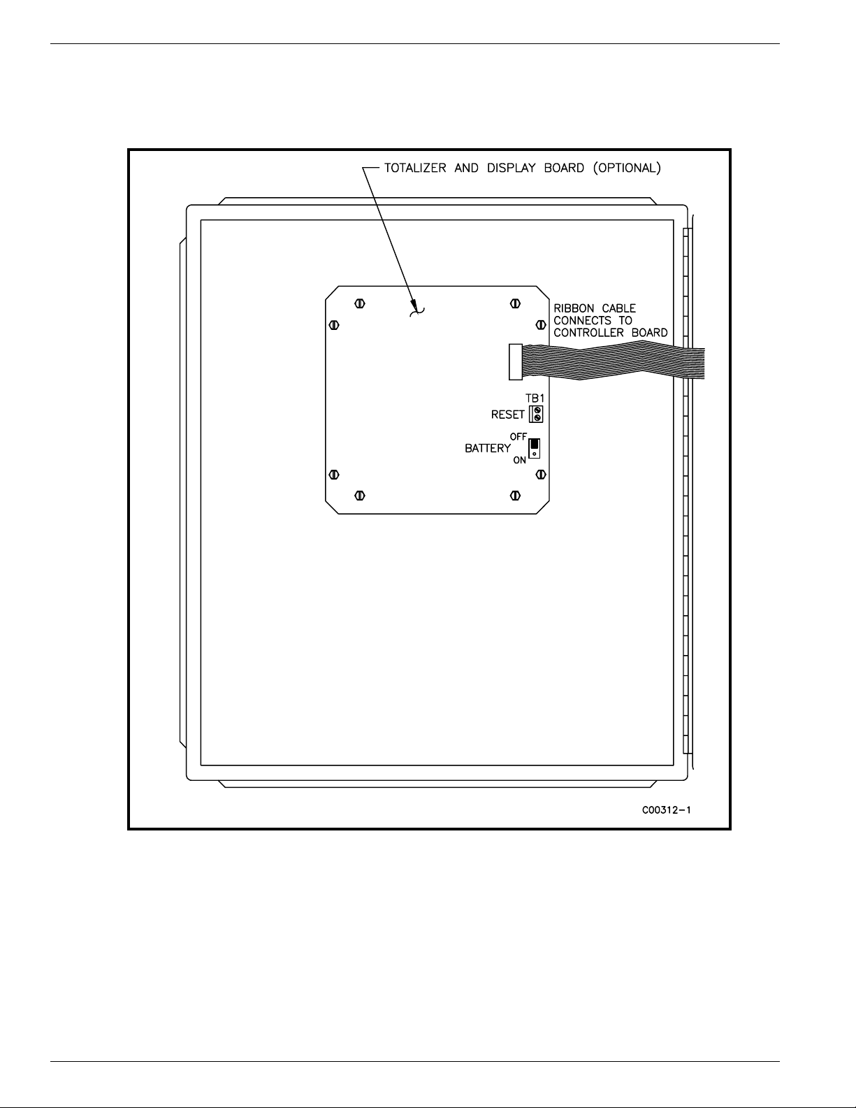
Apply Back-Up Battery Power
There is a totalizer option for the flowmeter. This option has a backup battery that keeps power applied to the
memory that holds the accumulated count during loss of power. There is a jumper on the back of the totalizer and
display board that needs to be repositioned to the ON position. See Figure 3-1 for the jumper location. The
estimated life of the battery is 3 years of power off operation. The battery power is drained only when the operating
power is off and the battery power is on. During shipment and storage, the battery jumper is OFF to conserve power.
Apply Power
Warning:
Verify the wiring, then apply power to the flowmeter. There are no special instructions for shutdown of the
flowmeter; just remove the operating power.
Wait a minimum of 5 minutes for flowmeter to stabilize. The display will indicate the current media flow. There are
no operator actions needed because the flowmeter operates from the factory settings.
When an open flowmeter has power applied, the operator assumes all responsibility for
conformance to safety standards and safe practices.
If the display is blank, is out-of-range for the expected values or is obviously not right then turn off the power and go
to Chapter 5 - Troubleshooting, to find the problem.
Operator Interaction
There is little need for interaction between the operator and flowmeter. The flowmeter is fully automatic when it
operates in the monitor mode. Setting the output signal and switch point relay closures as well as other options
depend on individual applications. FCI advises the use of factory default settings that the flowmeter was ordered
with. Do not reset the flowmeter's operating values by trial and error. Standard output options, such as a switch
point relay closure, operate automatically as a function of the output signal level.
A calibration table can be found in the back of this manual. The table shows a listing of the actual mass flow values
as indicated by the output signal. For example: using the standard 4-20 mA output signal, if the signal is 12.0 mA,
find 12.0 in the milliamp row and read across to the next column for the measured flow.
The display provides an instant readout of mass flow. The display shows only the flow rates between the upper and
lower limits of the calibrated range. For zero-based instruments the display will show zero whenever the flow rate is
below the calibrated lower limit. For non-zero-based instruments the display will read the minimum specified
flow rate.
Doc. No. 003162 Rev. F 3 - 1
Models MT86, MT86HT
Page 2
FLUID COMPONENTS INTL CHAPTER 3 - OPERATION
The flow totalizer accumulates the total quantity of media that has passed the flow element over a specific time.
Short two connector terminals together on the display board to reset the flow totalizer display, see Figure 3-1 for
details. In applications where the operator is required to reset zero, FCI recommends that these terminals be brought
out to a convenient reset switch.
Figure 3-1. Battery Jumper and Reset Locations
Non-Zero Based Calibration
This is a factory preset item.
In a non-zero based calibration, the low-limit output signal (4 mA) is equal to the minimum calibrated flow. The
minimum calibrated flow is a value greater than zero. The flowmeter's output signal will indicate the low-limit flow
signal (4 mA) from zero flow up to the low-flow limit parameter. Use a non-zero based calibration when the
minimum flow rate does not approach zero and the turndown ratios are small.
At no-flow, the minimum customer specified flow rate will appear on the display.
Models MT86, MT86HT 3 - 2 Doc. No. 003162 Rev. F
Page 3
CHAPTER 3 - OPERATION FLUID COMPONENTS INTL
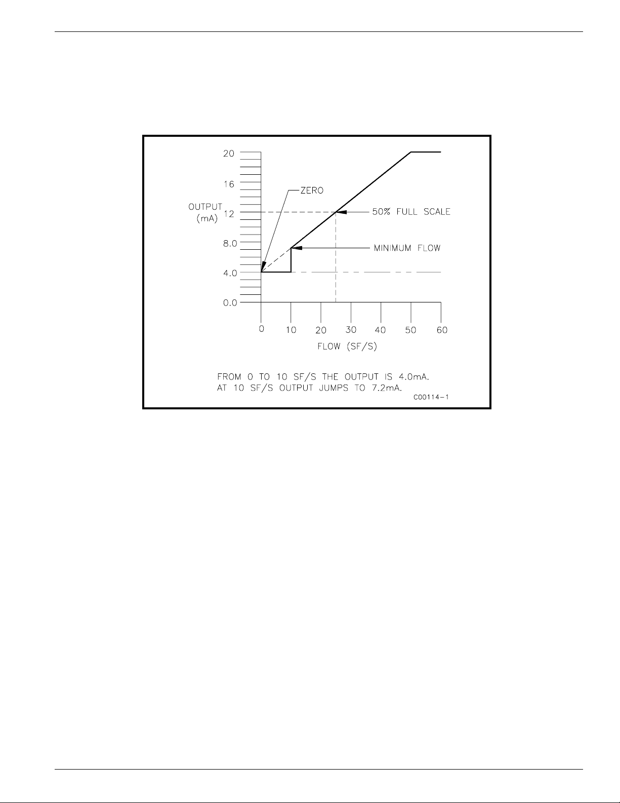
Zero Based Calibration
In a zero based calibration, the slope of the output signal is shifted so the low-limit flow output signal (4 mA) is
equal to zero flow. See Figure 3-2 for details. Flowmeters cannot measure zero flow accurately. The flowmeter will
readout the low-limit signal (4 mA) from zero flow up to the minimum calibrated flow. Then the output signal will
step up to the proper signal value of the mass flow.
The output signal is easier to interpolate when milliamp output is interfaced with control room 0 to 100% gauges;
50% of the signal will correspond to 50% of the maximum flow rate.
Zero based flowmeters have less signal to resolve over full scale. A zero based flowmeter with a turndown ratio of
10:1 will have 10% less output range to resolve flow (5.6 mA to 20 mA instead of 4 mA to 20 mA in a non-zero
based flowmeter).
Delta "R" Table
The actual data chart for this particular flowmeter can be found in the page protector at the back of this manual. The
Delta "R" part of this sheet gives the factory calibration measurement points of the Delta "R" differences between the
REF and ACT RTDs at certain flow rates. These measurements used by the factory determine the linearization
coefficients that are applied over the desired flow range. The corresponding current and voltage output readings are
also shown for the factory default settings.
The flow versus Delta "R" relationship is fixed for a given set of sensing points. There is a lookup table that is in the
page protector in the back of this manual. It is a printout of factory default settings for zero and offset readings. The
table shows the relationship between the displayed mass flow readings as they are related to the current output. The
output is calculated over the entire flow range with the use of a fitting equation and its respective coefficients.
The Delta "R" Table has a great deal of useful information. The table can be used to verify the correct operation of
the flow transmitter without the flow elements connected. By using the Delta "R" Table the flow element sensing
points are simulated with precision resistors or decade boxes.
Figure 3-2. Zero Based Calibration
Doc. No. 003162 Rev. F 3 - 3
Models MT86, MT86HT
Page 4

FLUID COMPONENTS INTL CHAPTER 3 - OPERATION
Generating New Delta "R" Tables
Using the FC81 Calibrator
1. Obtain the correct FC81 Field Calibrator for the MT86 or MT86HT Flowmeter:
Model FC81-8 is used for the MT86 with 1000 ohm flow element sensing point RTDs.
Model FC81-7 is used for the MT86HT with 100 ohm flow element sensing point RTDs.
2. Turn the operating power OFF and then disconnect the flow element cable from the terminal block TS1 on the
input board.
3. Connect the FC81 Field Calibrator cable to terminal block TS1 (sensing point 1). Also, connect the cable to one
of the output module connectors P7, P8, P9, or P11 that is located on the control board. A set of precision
decade boxes can be used instead of the FC81 Field Calibrator. Use the wiring diagram in Figure 5-4 to connect
the decade boxes.
4. On the control board, monitor the voltage (VDC) across TP10 (-) and TP9 (+) and from TP5 (-) to J8 (+).
5. On the output board, monitor the output signal (4 to 20 mA, 10 to 50 mA, 0 to 5 VDC, etc.,) with a DMM.
6. Close switch SW1-3 that puts the flow transmitter in the manual mode; this enables the head-select switch SW2
to select and monitor one sensing point.
7. Set the head-select switch SW2 to the number one (1) position.
8. Verify that switch SW4 is in the OP (OPerate) position.
9. Turn the operating power ON and let the system stabilize for a minimum of 5 minutes.
10. Set the FC81 Field Calibrator to the "READ VOLTS" position and remove the "ADD OHMS" by setting both
buttons to the OUT position. The voltage on the FC81 Field Calibrator can now be read. This is the same
voltage that is across TP5 (-) and J8 (+). Adjust the voltages by turning the "OHMS ADJUST" potentiometer.
11. On a blank Delta "R" sheet, write down the serial number of the flowmeter and the flow element serial number.
Blank Delta "R" sheets are obtained from FCI Customer Service.
12. Adjust the "OHMS ADJUST" potentiometer to give an output of 4.00 mA, which is zero volts on the FC81
Field Calibrator.
13. On the Delta "R" sheet record the TP9 to TP10 voltage, the TP5 to J8 voltage (which is the same voltage that
the FC81 Field Calibrator displays), the MILLIAMP OUTPUT and the LOCAL DISPLAY reading, if
applicable.
14. Depress the "SET OHMS" button on the FC81 Field Calibrator to display the new Delta "R" value for the
4.00 mA output. With the FC81 Field Calibrator "SET OHMS" Button depressed the flowmeter does not read
the Delta "R" values. The DMMs will give open circuit or random values.
15. Record the new Delta "R" on the data sheet. For Model FC81-8 Field Calibrator the displayed Delta "R" value
is divided by 10 . For Model FC81-7 there is no division necessary.
16. Set the calibrator to "READ VOLTS" and then adjust the "OHMS ADJUST" potentiometer to give the
following outputs: 5.00, 6.00, 8.00, 12.00, 16.00, and 20.00 mA and repeat Steps 13 through 16 for each.
17. Turn the operating power OFF. Then transfer the FC81 Field Calibrator cable to terminal block TS2.
18. Turn the operating power ON. Allow one minute for the flowmeter to stabilize.
19. Set the calibrator to "Read Volts" and repeat Steps 10 through 16. Remember to set the head-select switch,
SW2, to the number 2 position for sensing point number 2.
20. Repeat this procedure for all the remaining sensing points in the system. Remember to set the head-select switch
SW2 to the sensing point number that a new Delta "R" table is generated for.
21. When the Delta "R" table has been completed for the whole system, set the head-select switch to the total
number of sensing points in the system. For example, a flowmeter that has 4 sensing points should have the
head-select switch SW2 in position 4.
22. Open switch SW1-3, which places the flow transmitter in the automatic mode. This puts the flowmeter back into
the operation mode.
Models MT86, MT86HT 3 - 4 Doc. No. 003162 Rev. F
Page 5

CHAPTER 3 - OPERATION FLUID COMPONENTS INTL
New Calibration Procedure (in field)
Note:
The flowmeter is calibrated for use with specific customer applications and flow ranges. There may be
cause in the field to readjust the calibration to meet the field data or applications.
A flowmeter EPROM stores data to accommodate a range expansion of up to 25% above full range. If any changes
are performed a new Delta "R" table will be needed to represent the adjustment. If an output adjustment is made,
properly record the data and make it available for FCI records.
The flowmeter has a method for changing the span and zero adjustment in the field without losing the original factory
setting. The factory set span and zero will have jumpers J1, J5 and J7 installed, see Figure 5-3 for the electrical
assembly layout. FCI recommends that after any adjustment are made to the output, a new Delta "R" table should
also be made. Once an adjustment is made the original Delta "R" table does not represent the changes made.
Span Adjustment Only
The true flow rate of the process flow and the indicating milliamp output of the flowmeter need to be known before
going on with the following adjustment procedure. Record and have the information available for FCI to review.
The flow rate should be above 60% of full scale to justify a span adjustment only. Do not perform a span adjustment
if the data obtained is at a flow rate below 40%.
The following procedure is for sensing point (head) number one (1), but any sensing point can be used. The sensing
point number that is selected must match the head number selected at the head-selector, switch SW2.
1. Record the true flow of the process media and the flowmeter's milliamp output.
2. Turn the operating power OFF.
3. Connect the FC81 Field Calibrator to sensing point number 1. A set of precision decade boxes can be used
instead of an FC81 Field Calibrator. For the decade box wiring diagram refer to Figure 5-4.
Model FC81-8 is used for the MT86 with 1000 ohm flow element sensing point RTDs.
Model FC81-7 is used for the MT86HT with 100 ohm flow element sensing point RTDs.
4. Close switch SW1-3 that puts the flow transmitter in the manual mode; this enables the head-select switch SW2
to select and monitor one sensing point. Turn ON the operating power.
5. Adjust the FC81 Field Calibrator, or precision decade boxes, to give the milliamp output that was recorded in
Step 1. Record the Delta "R" that produced this output.
6. Remove jumpers J1 and J7. Add jumpers J2 and J8. This makes the span circuitry active.
7. With the FC81 Field Calibrator still at the Delta "R" from Step 5, adjust the span potentiometer, R16, to the new
output as calculated from the true flow measurement in Step 1.
8. From the Delta "R" table, put in the Delta "R" resistance value that represents the 4.0 milliamp output. Verify
that the output has not been affected by the span adjustment.
9. Turn OFF the operating power. Open switch SW1-3, and position the head-select switch SW2 to the number of
sensing points in the system. This puts the flowmeter back in the operation mode.
10. Remove the FC81 Field Calibrator or decade boxes and connect sensing point number 1 to the input board.
Span and Zero Adjustment
As with the span adjustment, field data is also needed to perform adjustments. The information that is needed is the
true flow rate and the indicating milliamp output of the flowmeter. Record and have the information available for
FCI to review. The procedure is basically the same as the span adjustment procedure. See Table 3-1 for jumper
positions.
Doc. No. 003162 Rev. F 3 - 5
Models MT86, MT86HT
Page 6
FLUID COMPONENTS INTL CHAPTER 3 - OPERATION
Table 3-1. Jumper Configuration For Output Adjustment
MODE
INSTALL JUMPER
J1 J2 J3* J4* J5 J6 J7 J8
Factory Set Span and
Zero
Span Only Adjust
Activated
YES NO YES NO YES NO YES NO
NO YES YES NO YES NO NO YES
Span and Zero Activation NO YES YES NO NO YES NO YES
* J3 and J4 will always be in this position unless the factory has authorized option changes.
1. Repeat steps 1 through 5 from above. Record the Delta "R" that was required to generate the milliamp output
for both the low and high flow rates.
2. Remove jumpers J1, J5 and J7. Add jumpers J2, J6 and J8, to make the span and zero circuitry active.
3. Adjust the FC81 Field Calibrator, or precision decade boxes, to the Delta "R" resistance that represents the low
flow milliamp output of Step 1.
4. Adjust the zero potentiometer, R17, on the control board to give the milliamp output that represents the
calculated low flow.
5. Adjust the FC81 Field Calibrator, or precision decade boxes, to the Delta "R" resistance value that represents
the high flow milliamp output from Step 1.
6. Repeat Steps 3 through 5 until the correct milliamp output matches the Delta "R" for the high and low flows.
7. Disconnect the FC81 Field Calibrator or precision decade boxes and reconnect the sensing point to its original
input board.
8. Return switch SW1-3 to the open position.
9. Set the head-selector, SW2, to the number of sensing points in the system. The flowmeter can be reset to the
factory set calibration with the use of the original jumper setup. The originally installed jumpers are J1, J3, J5
and J7. The above span and zero adjustments are not in effect when the flowmeter is in the original
configuration. The factory set calibrations are in control of the flowmeter. Table 3-1 shows the jumper settings
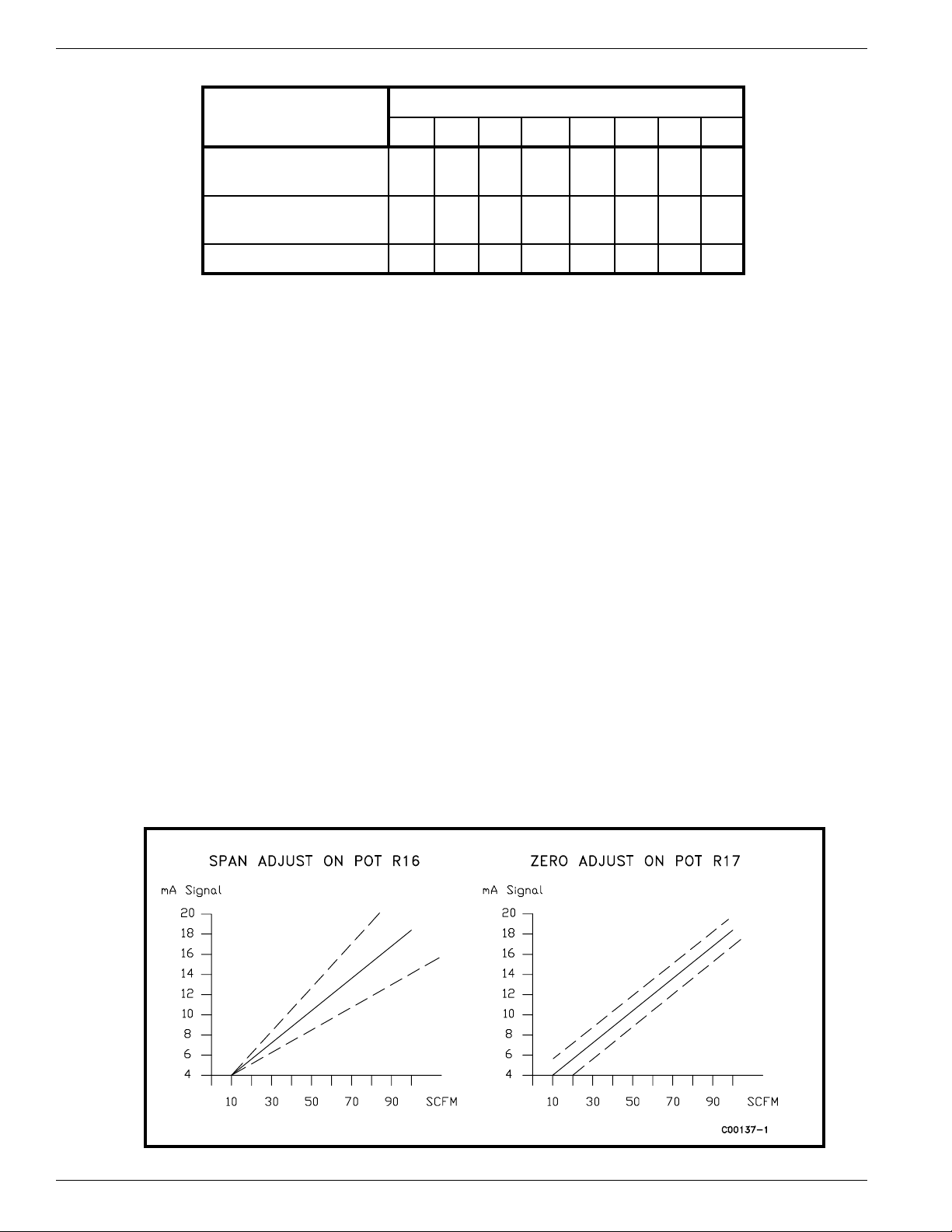
that are needed to make the zero and span adjustments active. Figure 3-3 shows the zero and span effects on the
flowmeter.
If only the zero adjust needs to be done, the span and zero jumpers will need to be set. Then proceed with the zero
adjustment.
Figure 3-3. Zero and Span Adjustment
Models MT86, MT86HT 3 - 6 Doc. No. 003162 Rev. F
Page 7

CHAPTER 3 - OPERATION FLUID COMPONENTS INTL
If a span and zero adjustment can not be done, the other choice for adjustment is an EPROM replacement. The
EPROM stores the data that represents the calibrated flow rate and the performance curve. FCI can provide a new
EPROM with the new data and/or range. The customer does have to provide FCI with Analog-to-Digital (A/D)
information and the flow rate so the EPROM can be made. Look at the Delta "R" table to get the A/D number. In
the Delta "R" table, one column is categorized as Voltage In Non-Linear, [TP9 (+) to TP10 (-)].
Use the following equation to calculate the A/D number for the Non-Temperature Compensated flowmeter only.
Write down the results in the chart shown in Figure 3-4.
A/D = ( [TP9 - TP10 (Vdc)]/2 )
5( 4096 )
X
For the Temperature Compensated flowmeter, the A/D equation is:
A/D = [( [TP9 - TP10 (Vdc)]/2 ) X (4096)]/(TC Gain)
TC Gain is a function of the reference temperature. Additional data for the TC Gain is needed. This data is the REF
SEN (+) to GND SEN (-) voltage from terminal block TS#.
Note:
This A/D versus flow information is needed for each flow element sensing point in the flowmeter.
FCI strongly recommends that as much data as possible be gathered because the calibration will be only as good as
the data supplied. Once a new EPROM is provided it will need to be installed (see the Repair procedure in
Chapter 5) and a new Delta "R" table generated (see the preceding section for the procedure).
Doc. No. 003162 Rev. F 3 - 7
Models MT86, MT86HT
Page 8
FLUID COMPONENTS INTL CHAPTER 3 - OPERATION
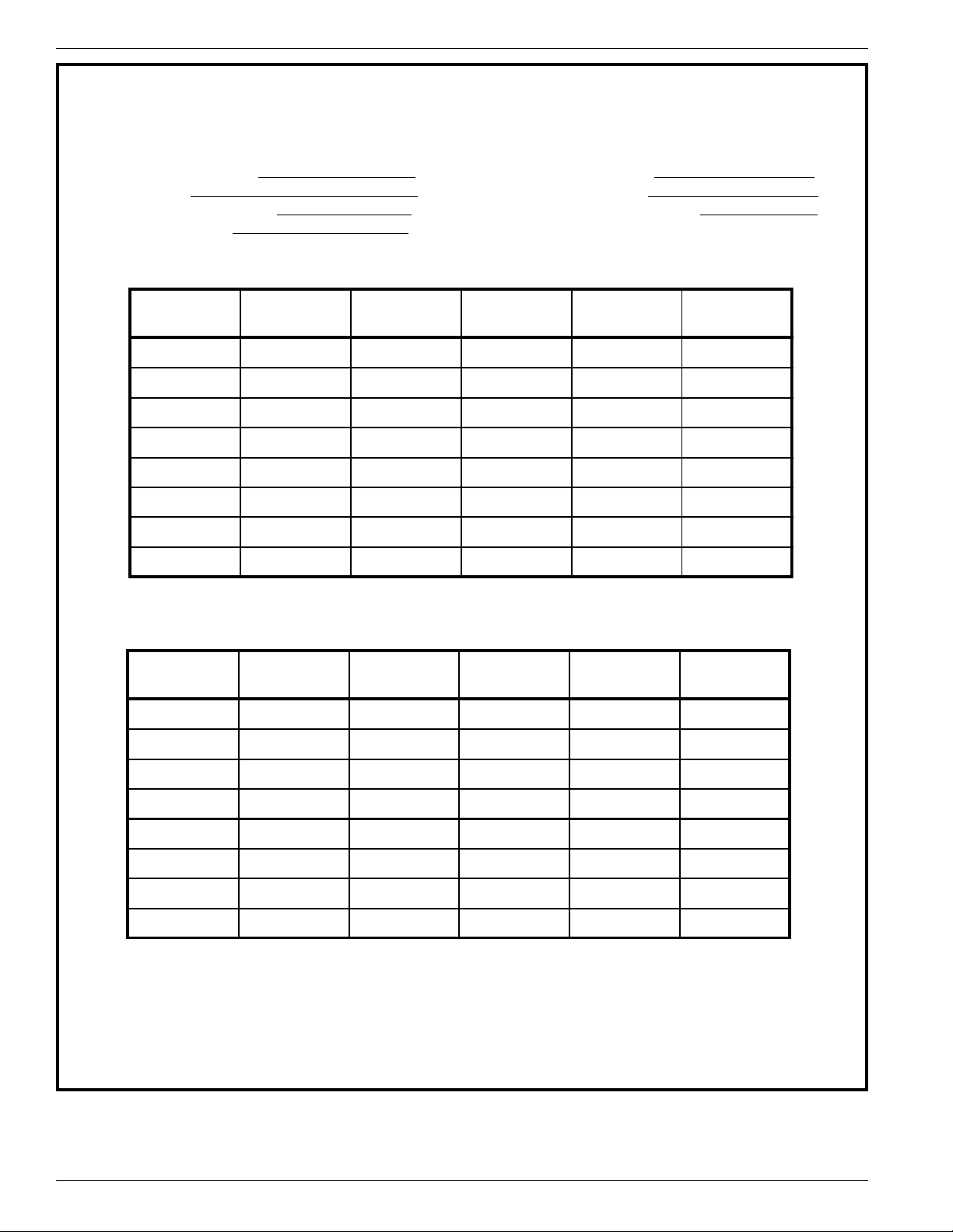
A/D DATA SHEET
SERIAL NUMBER_______________ DATE_______________
SERVICE ____________________ _ UNIT________________
FLOW RATE/LOAD _____________ COMPANY___________
OUTPUT (mA) _________________ (TOTAL OUTPUT)
SENSOR
POINTS
1
2
3
4
5
6
7
8
SENSOR
POINTS
1
2
DIS mA TP9-10 R. VDC* A/D**
DIS mA TP9-10 R. VDC* A/D**
3
4
5
6
7
8
* R. VDC is the reference voltage measured at the individual connectors from points numbered 2(-) to number 3 (+).
** A/D will be calculated at FCI with the above information.
Close dip switch 3 at SW1 (for manual operation) then dial the head selector, SW2, to the desired flow element.
Figure 3-4. A/D Data Sheet
Models MT86, MT86HT 3 - 8 Doc. No. 003162 Rev. F
 Loading...