

Page 1
Document 06EN003321 Rev. -24 Hour Factory Service Hot Line: 1 (800) 854-1993
GF92 Installation, Operation and
Troubleshooting Guide
A. To get the best results from the instrument, the sensor should be located 20 pipe diameters downstream from any
flow disturbance (valve, pipe elbow, etc.) and 10 pipe diameters upstream from any disturbance.
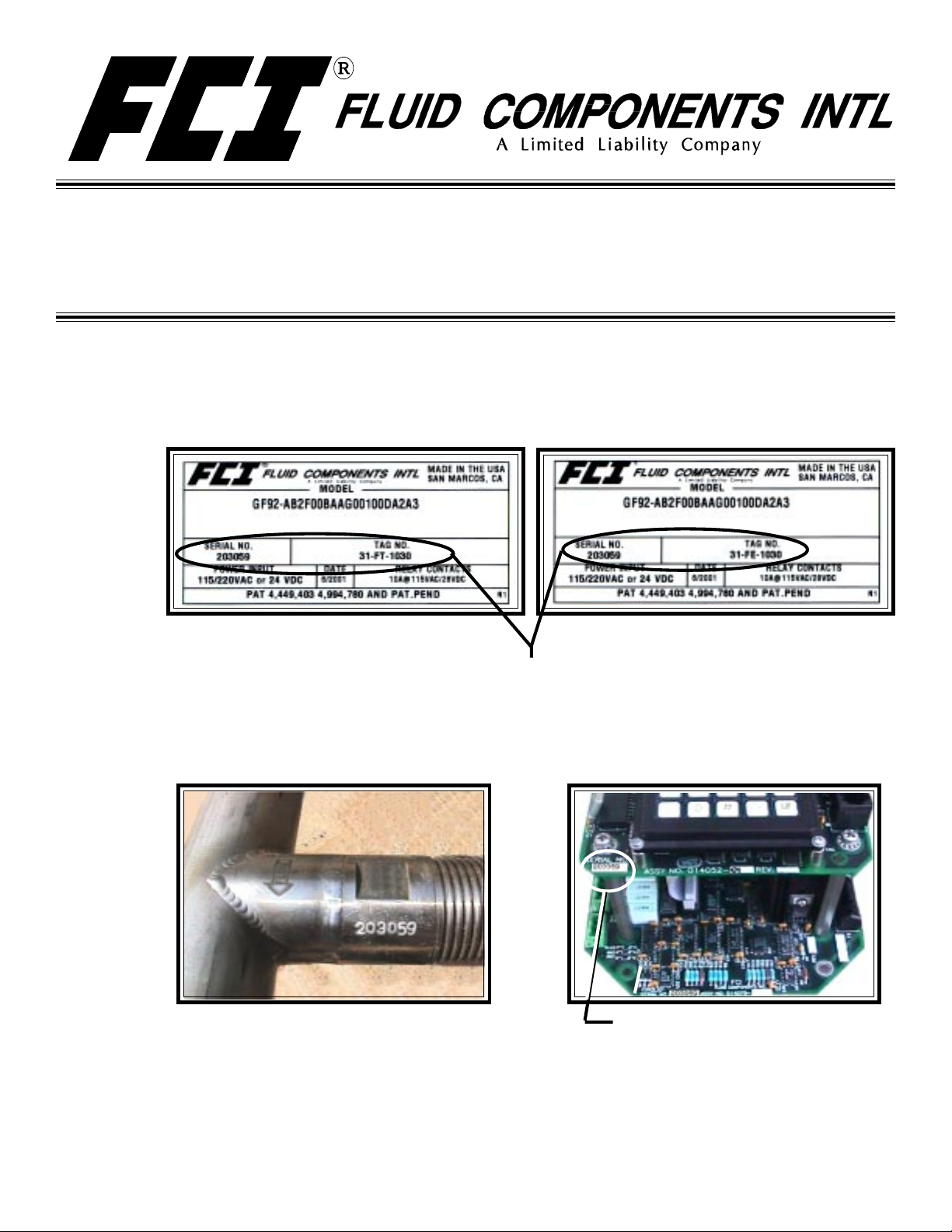
The instrument tags show the model number, tag number (if noted on the customer’s order), serial number along
with other important safety information. Compare this information with the appropriate pipe installation drawings
and calibration sheets to verify the instrument is the correct configuration.
Tag Location - Between Conduit Ports
On Local Enclosure
If the instrument is a remote configuration, the serial number on the enclosure tags must match. The recommended tag
number on the local enclosure will have an FT in the tag number. The recommended tag number on the remote enclosure
will have an FE in the tag number. (Tags are specified by the customer, “FE/FT” is a recommended naming convention .)
B. Verify the serial numbers on the enclosure(s), flow element and electronics match. The instrument may not work if the
serial numbers do not match. (The instrument has a remote transmitter enclosure (FT) and a local flow element
enclosure (FE).)
Flow Element Serial Number
Also Showing Flow Arrow
(Located near the FE enclosure.
It is also on the enclosure tag.)
(Top circuit board, lower left corner. It is also on
the transmitter’s (FT) enclosure tag.
Tag Location - Top Side of
Remote Enclosure
Electronics Serial Number
C. Recommended installation/troubleshooting tools are an open-ended wrench to fit the NPT connection, an open-
ended wrench to fit the flanged fitting nuts and bolts, a small flat blade screw driver for manipulating potentiometers,
both a medium flat blade screwdriver and a medium phillips head screwdriver for tightening connections, 3 mm allen
wrench for CENELEC approved instruments, a measuring tape for proper flow element placement, and a DVM for
Ohm/Voltage measurements.
Page 2
INSTALLATION, OPERATION AND TROUBLESHOOTING GUIDE FLUID COMPONENTS INTL
Step 2. Flow Element Installation
Alert: DO NOT change the orientation of the flow element in the enclosure as the interconnecting RTD and
heater wiring could be stressed and damaged. DO NOT apply any torque to the flow element
enclosure - only apply to the pipe surface itself.
Install the flow element, with the flow arrow (shown on Page 1) in the direction of media flow. The remote enclosure,
local enclosure, flow element and electronic transmitter serial numbers must all match.
For flange mount flow elements, attach the process mating flange with care. The correct orientation of the flow
element must be maintained to ensure the calibrated accuracy.
• Verify that the process media flow is in the same direction as the arrow on the flat machined area.
• Apply the appropriate gasket and/or sealant to flange mount as required.
• Mate flow element flange to process mount keeping flat oriented properly.
• Attach with bolt, two flat washers, lock washer and nut for each bolt hole, apply lubricant/sealant to male threads
and torque. Refer to ANISI B16.5 specifications.
For NPT pipe thread installations, apply sealant to the male threads. Carefully place in the process media line with the
machined flat facing up. Tighten the process connections. To avoid leaks do not overtighten or cross-thread
connections.
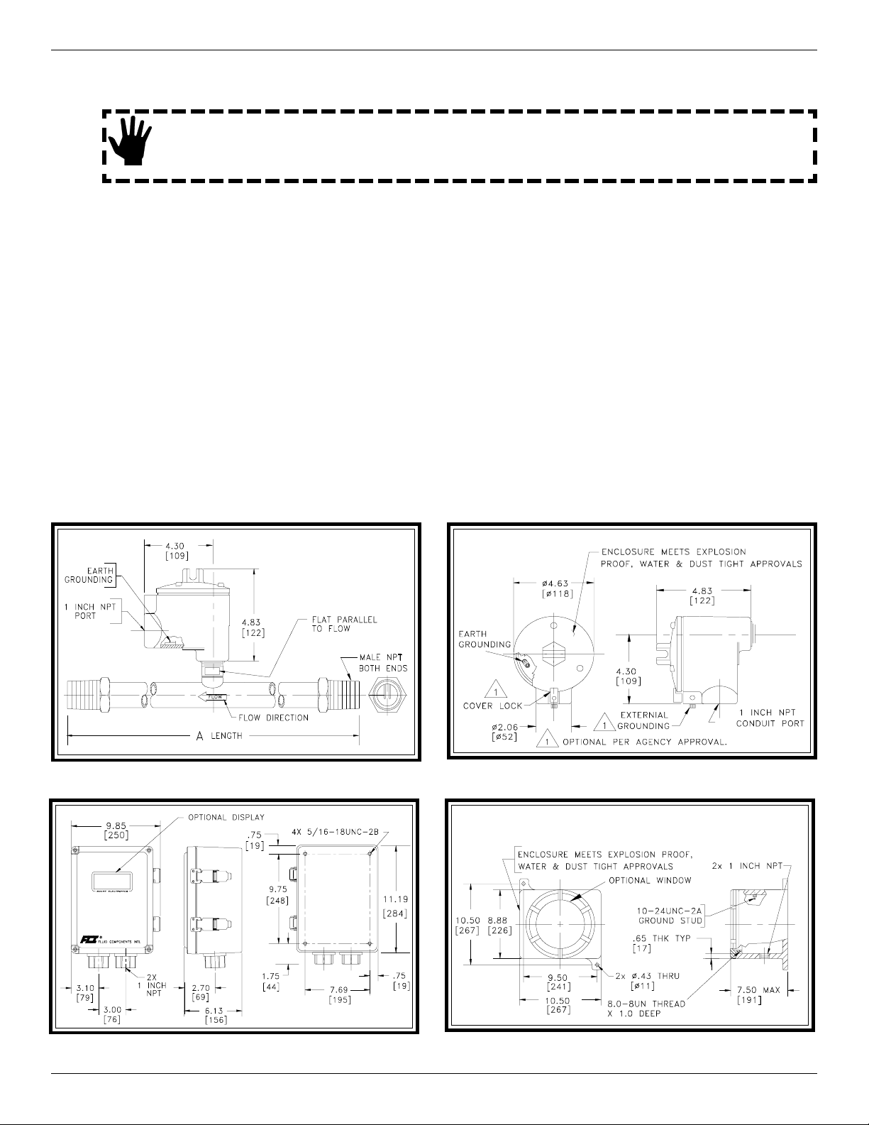
Shown below is the NPT mounting option. Other options are flange mount and butt weld mount. See the Installation
Section in the GF Series Manual, Document Number 06EN003229 for more details.
In-Line GF92 Flow Element and Enclosure Local NEMA 4 &7 Enclosure Dimensions
Remote Enclosure NEMA TYPE 4X Dimensions (Option) Remote Explosion Proof Enclosure Dimensions (Option)
Model GF92 Flowmeter 2 Doc. No. 06EN003321 Rev.-
Page 3
INSTALLATION, OPERATION AND TROUBLESHOOTING GUIDE FLUID COMPONENTS INTL
Step 3. Wiring Preparation
Before the instrument is opened to install the wiring, FCI recommends that the following ESD precautions be observed:
Use a wrist band or heel strap with a 1 megohm resistor connected to ground. If the instrument is in a shop setting there should
be static conductive mats on the work table and floor with a 1 megohm resistor connected to ground. Connect the instrument to
ground. Apply antistatic agents such as Static Free made by Chemtronics (or equivalent) to hand tools to be used on the
instrument. Keep high static producing items away from the instrument such as non-ESD approved plastic, tape and packing
foam.
The above precautions are minimum requirements to be used. The complete use of ESD precautions can be found in the U.S.
Department of Defense Handbook 263.
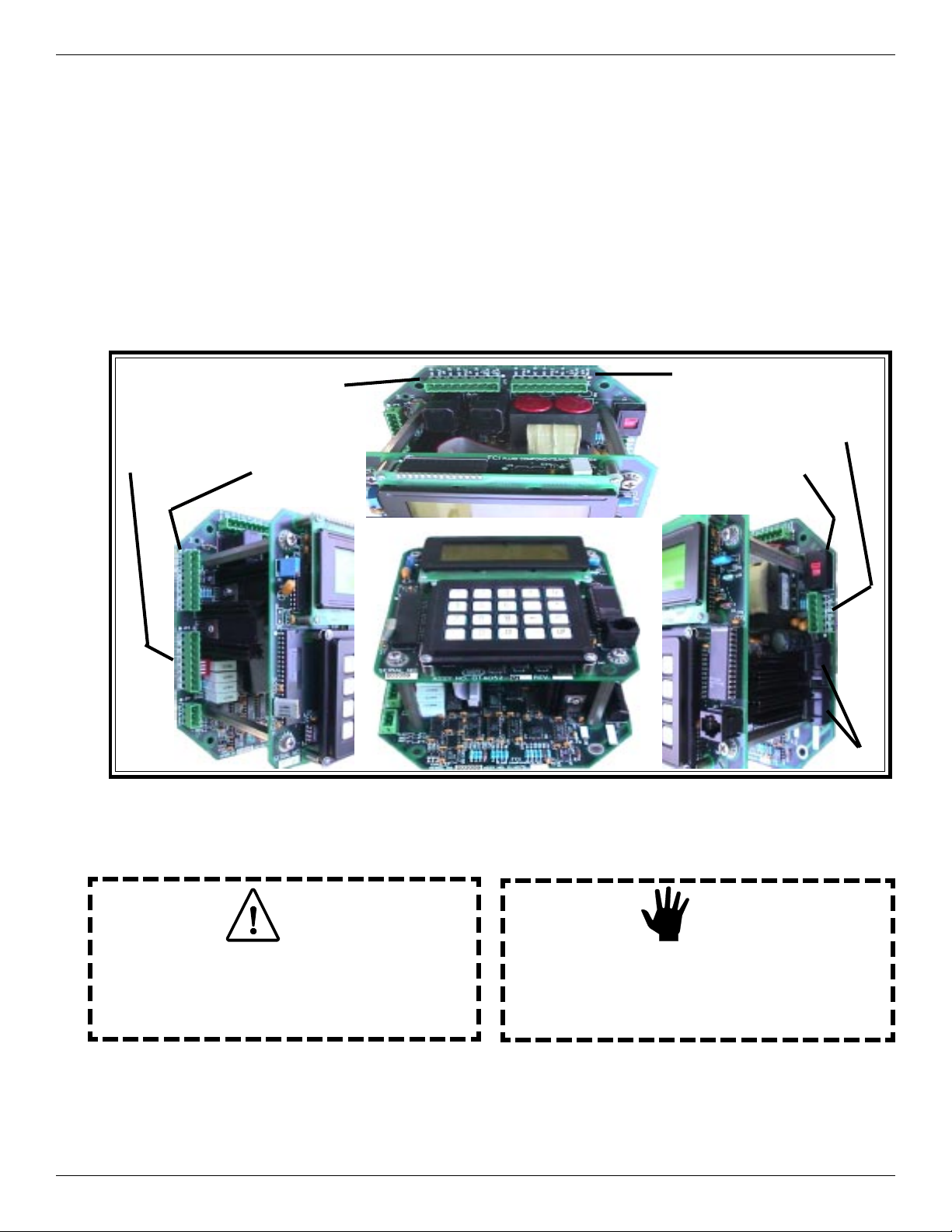
Open the instrument enclosure to expose the terminal strips. The orientation of the connectors are shown below:
JP3 - CUSTOMER
WIRING TO FLOW
ELEMENT
JP5
RELAY 2
JP6
AUXILIARY &
SIGNAL
OUTPUT
GF92 Terminal Strip, Power Option Switch and Fuse Orientation
JP4
RELAY 1
JP1
AC OR DC
POWER
SWITCH S1
( 115VAC
230VAC)
FUSES
Step 4. Wiring the Instrument
Caution:
Only qualified personnel are to wire or test this instrument.
The operator assumes all responsibilities for safe practices
while wiring or troubleshooting.
Wiring the Instrument into the Customer Application:
This section describes wiring to the transmitter inputs, outputs and interconnection cabling for the remote enclosure. For best
results route the output wiring through the opposite port from the power wiring. See the table on the next page to determine
the size of wiring to be used versus the length of the wire.
Doc. No. 06EN003321 Rev.
-
Alert:
The instrument contains electrostatic discharge (ESD)
sensitive devices. Use standard ESD precautions when
handling the flow transmitter.
3 Model GF92 Flowmeter
Page 4

Connection
Maximum Distance for AWG
10 ft.
(3m)
50 ft.
(15m)
100 ft.
(31m)
250 ft.
(76m)
500 ft.
152m)
1000 ft.
(305m)
AC Power 22 22 22 20 18 16
Relay (2A, at
220VAC)
24 22 20 16 12
Not
Recommended
Relay (10A, at
120VAC or 24VDC)
22 16 12 Not Recommended
Flow Element Wires
for Remote Option*
24 24 24 22 22 18
INSTALLATION, OPERATION AND TROUBLESHOOTING GUIDE FLUID COMPONENTS INTL
Wire Gauge Versus Distance Of Wire To Run
Wiring the Instrument’s Signal Output to the Customer Application:
For Current Output: 4 - 20 mA; connect a positive wire to + I OUT and a negative wire to OUT COM.
For Voltage Output: 0 - 5, 0 - 10 or 1 -5 Vdc; connect a positive wire to + E OUT and a negative wire to OUT COM.
Analog Output 2 is connected in a similar manor as Analog Output 1. ( For Voltage Output: 0 - 5, 0 - 10 or 1 -5 Vdc;
connect a positive wire to + E OUT2 and a negative wire to OUT 2 COM. For Current Output: 4 - 20 mA; connect a
positive wire to + I OUT2 and a negative wire to OUT 2 COM.) See GF Series manual 06EN003229 for details.
Analog Output Plug Location
Alert:
Customer Connections, Analog Output Diagram
Either voltage or current from the Analog Outputs can be connected to the customer application, not both.
(Example: Voltage and current from analog output 1 cannot be connected.) However, one Analog Output
can be wired for current and the other Analog Output can be wired for Voltage.
Model GF92 Flowmeter 4 Doc. No. 06EN003321 Rev.-
Page 5

INSTALLATION, OPERATION AND TROUBLESHOOTING GUIDE FLUID COMPONENTS INTL
Wiring the Flow Element:
Connect a shielded, 8 wire cable between the transmitter and the local enclosure terminal strip as shown below. Be sure
the shield (ground wire) is connected to JP3 GND along with the wire from terminal block terminal 2. Do not connect the
shield to the local enclosure (leave it floating).
Local Enclosure Wiring Diagram
Flow Element Transmitter
Terminal Block JP3 (Terminal No.)
Terminal 5 (ACT) ACT SEN (4)
Terminal 5 (ACT) ACT EXC (6)
Terminal 4 (G ND SE N) GND SEN (2)
Terminal 3 (REF) REF SEN (3)
Terminal 3 (REF) REF EXC (5)
Terminal 2 (GND) GND (1)
Terminal 1 (HTR) HTR E XC (7)
Terminal 1 (HTR) HTR S E N (8)
Flow Element Wiring Table
(Be sure the jumper is in place
Terminal 2 to terminal 4.)
Wiring the Output Relays:
The instrument contains two sets of alarm output relays (connectors JP4 Relay Output 1, and JP5 Relay Output 2). They
can be wired by the customer as desired. (NO = Normally Open, NC = Normally Closed, Pole = Common)
Doc. No. 06EN003321 Rev.
Output Relay Wiring Diagram
-
Connector JP3Flow Element Wiring Diagram
Connectors JP5 and JP4
5 Model GF92 Flowmeter
.
.
Page 6

INSTALLATION, OPERATION AND TROUBLESHOOTING GUIDE FLUID COMPONENTS INTL
Wiring the Input Power:
Caution:
FCI recommends placing an ON/OFF switch in line with the power source. When JP1 is connected to
the power source the instrument is ON.
AC or DC power can be used to operate this instrument. For best results route the output signal wiring through the left port
of the instrument enclosure and the power input wiring through the right port. See the wiring table on Page 4 to determine
the minimum size of wiring to be used versus the length of the wire run to the power source.
115 or 230 VAC Power Option
The input power can be switched from 115 Vac to 230 Vac by moving switch S1 to the correct setting. (The instrument
requires only AC or DC to be connected, not both.) Connect the hot side of the AC Line to AC Line, the neutral side to AC
NEUT, and ground to EARTH GND. (Do not connect the local enclosure shield wire to the EARTH GND on this plug.)
24 VDC Power Option
If DC power is used, the AC Input and switch S1 are not pertinent. Wire the positive 24 volt input to +24V. Connect the
negative wire to DC GND.
Input Power Location
Step 5. Operation
The instrument has been configured and calibrated to custom specifications. In-depth programming of the instrument in the
field should not be necessary.
Apply power to the instrument. Wait 10 minutes for the instrument to stabilize. During this period the instrument may indicate
a high flow condition. When the instrument is powered up, the instrument will display an initialization sequence. Then the
instrument will display the normal operation information. Shown below is the normal operation window.
Switch S1
Connector JP1
Input Power Wiring Diagram
Flow Rate
Output Channel #
Calibration Group #
Model GF92 Flowmeter 6 Doc. No. 06EN003321 Rev.-
CH1: 5056.3 SCFM
CH2: 71.2 °F
S =
435226 SCF
(grp1)(ed)(norm)(m)
Relay Status
Normal Operation Window
Mode
Flow Units
Process Temperature
Totalizer (If Enabled)
Sample (Flashes) Rate
Page 7

INSTALLATION, OPERATION AND TROUBLESHOOTING GUIDE FLUID COMPONENTS INTL
Menu Control
The prompt line displays appropriate key strokes for the required menu level. If a key is pressed that is not valid for that
menu, Invalid Response will flash briefly across the prompt line. The key pad and key assignments are shown below:
Menu Level
Title
Available Selections
3.1.2 STD VOLUME
1=Cu feet
3=Cu meter
3=Liters
(CF)?
Current Selection
Prompt Line
Display Characteristics
1 2 3 Y N
4 5 6
7 8 9 P
ENTR
0 #
_
HOME
Key Pad
.
UP
Key
0 - 9
Y
N
-
•
P
ENTR
HOME
UP
Key Name
Numeric
Yes
No or (N)ext
Minus
Decimal Point
Back Space
(P)rv or Previous
Enter
Home
Up
Key Assignments
Action
Selects options and enters
numbers
Enter a yes response
Enter a no response or scrolls
to the next screen
Enter a minus sign
Enter a decimal point
Moves cursor back one space
Scrolls to the previous screen
Enters a numeric value or
response
Returns to the Main Menu or
escapes from routines
Move current menu up one
level
At any time, the HOME key can be pressed and the main menu will display. HOME can be used to escape from most
routines, or restart a progression into the menu structure.
When (N)ext is displayed on the prompt line, more than two menu selections are available. Press N to scroll through all the
selections.
The UP key, will back-out of a menu level. The menu moves back one level each time the UP key is pressed. The UP key
only functions when UP is displayed on the prompt line.
To make a selection, press the numeric key associated with the desired menu selection. The selection does not have to be
displayed, but it must be one of the available selections.
The quick operation menu is shown below:
0.0 MAIN MENU
1 = Normal Operati on
2 = Por t Setup
3 = Display Setup
4 = Miscellaneous
CH1: 5056.3 SCFM
CH2: 71.2
S
= 435226 SCF
(grp1) (dd) (mode N) (m)
F
QUICK OPERATION
MENU
Normal Operation
2.0 PORT SETUP
1 = Analog Output
2 = Relays
3 = Comm Output
4 = Aux Input
3.0 DI SPLAY SETUP
1 = Flow Setup
2 = Temperatur e Setup
3 = Totalizer Setup
4 = Sample Rate
4.0 MISCELLANEOUS
1 = Set Group
2 = Corrector Setup
3 = Password Setup
Doc. No. 06EN003321 Rev.
-
7 Model GF92 Flowmeter
Page 8

INSTALLATION, OPERATION AND TROUBLESHOOTING GUIDE FLUID COMPONENTS INTL
Step 6. Troubleshooting
In the event that the instrument does not operate as expected use the table below:
Problem Solution
No Display Check Fuses (below JP1).
Verify S1 is switched to the correct input voltage for AC applications.
Verify correct power is applied
Verify the ribbon cable between the upper and lower circuit boards is
solidly connected and the red stripe is on pin 1.
No Display or Dim Dis play Adjus t pot R1 on the upper left of the top circuit board. If there is no
change in the display return the pot to the original setting.
Display is Locked Up Press HOME and then 1 to return to normal operation.
Reset the instrument by cycling the power.
Readings S eem Incorrect Verify the serial number of the flow element and the flow transmitter
are the same serial number.
Verify the flat on the flow element is parallel to the pipe and the flow
flow arrow is pointed in the direction of the flow stream.
Verify the sensor is mounted in the center of the pipe.
Verify the calibration data sheet m atches the process configuration.
Verify all jacks and plugs are all firmly seated and the wiring to them
is correct and secure.
If there are still problems with the instrument, see the Troubleshooting Section in the GF Series Manual,
Document Number 06EN003229. To acquire a manual call your local FCI sales representative.
Notice of Proprietary Rights
This document contains confidential technical data, including trade secrets and proprietary information which are the property of Fluid Components Intl
(FCI). Disclosure of this data to you is expressly conditioned upon your assent that its use is limited to use within your company only (and does not include
manufacture or processing uses). Any other use is strictly prohibited without the prior written consent of FCI.
Visit FCI on the Worldwide Web: www.fluidcomponents.com
1755 La Costa Meadows Drive, San Marcos, California 92069 USA - 760-744-6950 - 800-854-1993 - Fax 760-736-6250
European Office: Persephonestraat 3-01 5047 TT Tilburg - The Netherlands - Phone 31-13-5159989 - Fax 31-13-5799036
© Copyright 2001 Fluid Components Intl a limited liability company All Rights Reserved
Model GF92 Flowmeter 8 Doc. No. 06EN003321 Rev.-
 Loading...