

Page 1
Installation, Operation and Maintenance
GF03 Flowmeter Series
[
]
Doc 06EN003352
Page 2

Page 3

FLUID COMPONENTS INTERNATIONAL LLC http://www.fluidcomponents.com
1. General Information
2. Installation
3. Operation
Description ................................................................................................................................. 1
Theory of Operation ................................................................................................................. 1
Sensing Element ........................................................................................................................ 1
Flow Transmitter ....................................................................................................................... 2
Technical Specification ............................................................................................................ 2
Receiving/Inspection ................................................................................................................ 5
Packing/Shipping/Returns ....................................................................................................... 5
Factory Calibration Note .......................................................................................................... 5
Pre-Installation Procedure ....................................................................................................... 5
Install Flow Element ................................................................................................................. 6
Install Transmitter ..................................................................................................................... 8
Customer Wiring ....................................................................................................................... 9
Wiring Diagram, Remote with Veri-Cal ............................................................................... 10
Wiring Diagram, Remote ......................................................................................................... 11
Introduction ................................................................................................................................13
Start-Up Procedure ................................................................................................................... 13
Operation .................................................................................................................................... 13
Advanced Features .................................................................................................................... 27
Calibration Functions, Menu 7.0............................................................................................ 36
Veri-Cal, In-Situ Calibration Verification ............................................................................ 36
4. Maintenance
5. Troubleshooting
6. Appendices
Maintenance ............................................................................................................................... 39
Equipment Needed .................................................................................................................... 41
Quick Check............................................................................................................................... 41
In-Depth Troubleshooting - The Flow Element................................................................... 42
In-Depth Troubleshooting - The Flow Transmitter ............................................................. 43
In-Depth Troubleshooting - The Installation........................................................................ 44
In-Depth Troubleshooting - The Process .............................................................................. 44
Defective Parts ........................................................................................................................... 47
Spares .......................................................................................................................................... 47
Customer Service ...................................................................................................................... 47
Appendix A - Outline Drawings and Wiring Diagrams ..................................................... 49
Appendix B - Glossary of Terms ............................................................................................ 51
Appendix C - Customer Service ............................................................................................. 55
NOTICE OF PROPRIETARY RIGHTS: This document contains confidential technical data, including trade secrets and
proprietary information which is the property of Fluid Components International LLC (FCI). Disclosure of this data to you
is expressly conditioned upon your assent that its use is limited to use within your company only (and does not include
manufacture or processing uses). Any other use is stricly prohibited without prior written consent of FCI.
Doc. No. 06EN003352 Rev. B Model GF03 Flow Meter
Page 4

FLUID COMPONENTS INTERNATIONAL LLC http://www.fluidcomponents.com
THIS PAGE INTENTIONALLY LEFT BLANK
Model GF03 Flow Meter Doc. No. 06EN003352 Rev. B
Page 5

FLUID COMPONENTS INTERNATIONAL LLC http://www.fluidcomponents.com
1. General Information
Description
Theory of Operation
This document describes the procedures required to install, operate, maintain, and troubleshoot
the Model GF03 Flowmeter. There are a wide range of possible configurations and information
related to the optional features. The flowmeter is composed of a remote thermal dispersion
sensing transducer (flow element) connected to a microprocessor-based electronics control
and display package (flow transmitter). The flow element is attached to the flow transmitter
thru a cable of up to 1000 feet or 300 meters (remote instrument).
The instrument is designed to operate in gaseous flow metering environments. The flowmeter
is factory calibrated to handle a range of flows.
The primary flow element consists of two thermowells of the same size, shape and mass. One
thermowell contains a platinum RTD and a heater element. The other contains one RTD. The
RTD located with the heater element is called the active RTD. The other RTD is referred to
as the reference RTD. Since the active RTD is embeded in the heater, the temperature of the
active thermowell is always above the temperature of the process media. The temperature at
the reference RTD is the temperature of the process media. When the process media is flowing
past the active RTD a quantity of heat is carried off into the flow stream. The amount of heat
taken from the active RTD is a function of the process media mass flow rate. A ∆T
(temperature) exists between the two thermowells and a proportional ∆R (ohms resistance)
exists between the active and the reference RTDs. The ∆R is measured by the flow transmitter.
The relationship of ∆R to the calibrated flow rate is calculated by the flow transmitter and is
converted into both analog and digital outputs.
The Gas Compensation element provides a ∆R value similar to the primary flow element. This
value is a no-flow ∆R based on the thermo physical properties of the gas mixture minus any
flow component. This value is used to correct gas composition changes in the Transmitter
microprocessor.
Sensing Element
The standard sensing element is an all welded 316L stainless steel insertion probe. The
element consists of the primary flow element located on the end of the probe and the
compensator element located in the insertion pipe. The optional Veri-Cal inlet tube runs
the length of the insertion pipe exiting into the base of the primary flow element. This tube
allows the Veri-Cal system to distribute a repeatable flow rate on the primary flow element
for calibration verification purposes.
Figure 1 - Flow Element
Doc. No. 06EN003352 Rev. B 1 Model GF03 Flow Meter
Page 6
FLUID COMPONENTS INTERNATIONAL LLC http://www.fluidcomponents.com
Flow Transmitter
The other component of the flowmeter is the flow transmitter. The basic functions of the flow
transmitter are to provide power to the flow element, measure the Differential Temperature
(∆T) between the two RTDs as a function of resistance, amplify and linearize the Differential
Resistance (∆R) measurement of the flow element and provide a proportional output signal.
This output signal is calibrated to the flow rate as a function of standard velocity or volume.
To perform these functions, microprocessor-based electronic circuitry is employed to acquire
the analog voltage signals from the RTDs, digitize and interpret the information.
The microprocessor-based electronics provides maximum flexibility and ease of operations
with a menu-driven selection of control, monitoring, display and driver options.
Technical
Specifications
Figure 2 - Flow Transmitter
INSTRUMENT
Flow Range:
Insertion Flow Element: 0.5 to 275 SFPS [0.20 to 84 NMPS]
— Air at standard conditions; 70°F [21.1°C] and 14.7 psia [1.01325 bar (a)].
Media: All gases that are compatible with the flow element material.
Accuracy:
Flow: ±2% to 5% of reading above 1 SFPS in open stack environments.
Temperature: ±2°F (display only, flow rate must be greater than 5 AFPS)
Repeatability:
Flow: ±0.5% reading
Temperature: ±1°F (flow rate must be greater than 5 AFPS)
Turndown Ratio:
Standard: Factory set and field adjustable from 2:1 to 600:1 within calibrated flow range.
Temperature Compensation:
Standard: ±30°F [±-1°C] Optional: ±100°F [±38°C]
Agency Approvals (Pending):
FM, CSA, CE MARK, (EMC Directive 89/336/EEC), ATEX, CCE, CRN.
Calibration: Performed on NIST traceable equipment.
FLOW ELEMENTS
Material of Construction: All-welded 316L stainless steel. Elements with pressure
transducer have braze and 300 series SST.
Operating Pressure: 0 to 250 psig [0 to 17 bar (g)]
Operating Temperature: Process temperature -40°F to 350°F [-40°C to 177°C];
Process Connection: 1” male NPT, Flange (ANSI), Packing Gland 1-1/4” NPT or Flanged.
Model GF03 Flow Meter 2 Doc. No. 06EN003352 Rev. B
Page 7

FLUID COMPONENTS INTERNATIONAL LLC http://www.fluidcomponents.com
FLOW TRANSMITTER
Operating Temperature: 0 to 140°F [-18 to 60°C]
Input Power: 115 Vac ± 15 V; 230 Vac ± 30 V; 22 to 30 Vdc; 23 Watts Max.
Output Signal
Analog:
Two independent, AC power isolated, which can be set as follows:
4-20 mA, 600 ohm maximum load
0-10 Vdc, 5000 ohm minimum load
0-5 Vdc, 2500 ohm minimum load
1-5 Vdc, 2500 ohm minumum load
One optional pressure output:
4-20 mA, 600 ohm maximum load
One gas compensator output:
4-20 mA, 600 ohm maximum load.
Two programmable 10 amp (115 Vac or 24 Vdc) relay switch points.
Communication Port: EIA-232 [RS-232C]
Display: 4 line/20 character per LCD line, indicating flow rate and process temperature
and/or totalized flow.
Communicator(optional): Hand held plug-in interface (model FC88).
Remote Enclosure
Standard: NEMA/CSA Type 4X (equivalent to IP66) Fiberglass
Option: Aluminum rated for hazardous location use Class I and II, Division 1 and 2,
Group B, C, D, E, F, G (previously referred to as NEMA 7 and EEx d IIB) resists the
effects of weather and corrosion.
Doc. No. 06EN003352 Rev. B 3 Model GF03 Flow Meter
Page 8

FLUID COMPONENTS INTERNATIONAL LLC http://www.fluidcomponents.com
THIS PAGE INTENTIONALLY LEFT BLANK
Model GF03 Flow Meter 4 Doc. No. 06EN003352 Rev. B
Page 9

FLUID COMPONENTS INTERNATIONAL LLC http://www.fluidcomponents.com
2. Installation
Receiving / Inspection
Packing / Shipping
and Returns
Factory Calibration
Note
Pre-Installation
Procedure
w Unpack carefully, observe Electro-Static Discharge (ESD) precautions if handling the
flow transmitter.
w Inspect for damage to the flow element and the flow transmitter.
w Verify that all items in the packing list were received and are correct.
w Verify the Delta R Data Sheet and the Instrument Information Sheet are present.
If the above items are satisfactory then proceed with installation. If not, then stop and
contact the FCI customer service representative for instructions.
These issues are addressed in Appendix C - Customer Service.
The flowmeter is factory calibrated to the flow range specified in the order. There is no
need to perform any verification or calibration steps prior to installing and placing the
flowmeter in service.
Caution:
The flow transmitter contains electrostatic discharge (ESD) sensitive
devices. Use standard ESD precautions when handling the flow transmitter.
See below for ESD details.
The GF Series Flowmeter is not designed for weld-in-place applications. Never
weld into the installation or to a structural support.
Use Standard ESD Precautions
Use standard ESD precautions when opening an instrument enclosure or handling the flow
transmitter. FCI recommends the use of the following precautions: Use a wrist band or heel
strap with a 1 megohm resistor connected to ground. If the instrument is in a shop setting there
should be static conductive mats on the work table and floor with a 1 megohm resistor
connected to ground. Connect the instrument to ground. Apply antistatic agents to hand tools
to be used on the instrument. Keep high static producing items away from the instrument such
as non-ESD aproved plastic, tape and packing foam.
Prepare or Verify Flow Element Location
Prepare the media process pipe for installation or inspect the already prepared location to
ensure the instrument will fit into system. Prepare the necessary sealants or gaskets to provide
a leak proof installation.
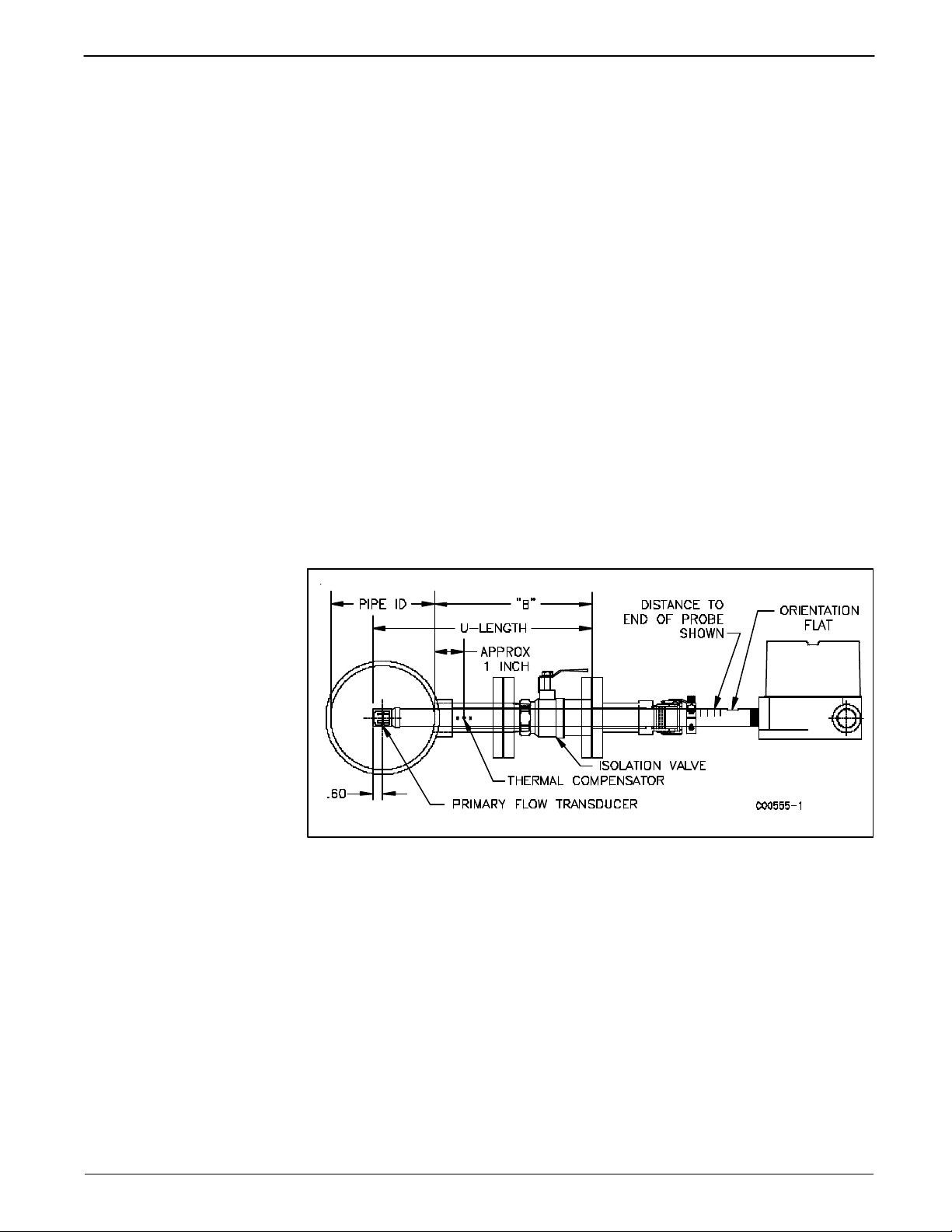
The U-length should be double checked when installing the flow element into the process
media. The U-length is determined at the factory order time and is the distance that places
the flow element head center line in the center line of process media. See Figure 3. The greatest
accuracy is achieved when the flow element is mounted at least 20 diameters downstream and
10 diameters upstream from any bends or interference in the process pipe or duct.
Doc. No. 06EN003352 Rev. B 5 Model GF03 Flow Meter
Page 10

FLUID COMPONENTS INTERNATIONAL LLC http://www.fluidcomponents.com
Verify Serial Numbers
Verify the flow element and flow transmitter have the same serial number, as they are to be
installed as a matched set.
Verify Dimensions
Verify the flow element and flow transmitter dimensions as shown in Appendix A.
Verify Flow Direction for Flow Element Orientation and Placement
Note: Correct flow element placement in the measurement stream is vital for obtaining
accurate flow readings. Before mounting the flow element, check the options
ordered for correct orientation and insertion length at the planned site of installation.
The flow element thermowells must be positioned in the same orientation to the process flow
as they were during calibration (refer to the Instrument Information Sheet). Failing to install
the flow element correctly may reduce the accuracy of the flowmeter. Be sure the flow arrow
points in the direction of flow.
The flow element thermowells are to be placed as shown in Figure 3, with the end of the
shroud 0.6 inches past center line.
There is a flat area machined perpendicular to the thermowell plane. Adjust the flow element during installation so the flat area is parallel, with in ±2°, to the direction of process
media flow.
Adjustable / Retractable
Flow Element Assembly
Caution: Do not over-tighten the flow element. The RTD's can be
dammaged if the flow element is forced into the far wall of the
pipe or vessel.
Select one of the following installation procedures which is applicable to the unit being
installed.
NPT and flange packing gland mounts are available. The valve assembly with appropriate
connections are typically customer supplied. Follow the pipe or flange mounting procedure
below.
NPT Pipe Mounting
w Apply sealant compatible with the process media to male threads. Carefully insert into
process mount. Threads are right-handed. Tighten with an open-end wrench on the
hexagonal surface provided. Rotate until snug.
Figure 3 - NPT Pipe Mount
Model GF03 Flow Meter 6 Doc. No. 06EN003352 Rev. B
Page 11
FLUID COMPONENTS INTERNATIONAL LLC http://www.fluidcomponents.com
Flange Mounting
w Attach the process mating flange with care. The correct orientation of the flow element
must be maintained to ensure the calibrated accuracy.
w Verify that the process media flow is in the same direction as the arrow on the FLAT.
w Apply the appropriate gasket and/or sealant to flange mount as required.
w Mate flow element flange to process mount keeping flat oriented properly.
w Attach with bolt, two flat washers, lock washer and nut for each bolt hole, apply lubricant/
sealant to male threads and torque. Refer to ANISI B16.5 specifications.
General Mounting
w Tighten packing nut until internal packing is tight enough so that the friction fit on the
shaft is adequate to prevent leakage but not prevent the shaft from sliding. Position the
flat horizontal with arrow in direction of process flow.
w Proceed to insert the flow element into process media line. For the medium pressure
packing gland use the adjusting nuts on the all-thread to pull the flow element into proper
predetermined depth position.
w Tighten the opposing lock nuts on the all-threads. Tighten the packing nut another 1/2
to 1 turn until tight (approximately 65 to 85 ft-lbs torque).
w Rotate split ring locking collar to line up with connecting strap welded to packing nut.
Tighten the two 1/4-28 hex socket cap screws on the split ring locking collar. Open valve
- check for process media leakage.
w Reverse these steps for removal.
Figure 4 - Flange Mount
Doc. No. 06EN003352 Rev. B 7 Model GF03 Flow Meter
Page 12

FLUID COMPONENTS INTERNATIONAL LLC http://www.fluidcomponents.com
Install
Transmitter
Warning: Installation of an FCI instrument should only be performed by properly trained
personnel in accordance with the current edition of the National Electrical
Code. Ensure that all power is off. Any instances where power should be
applied to the instrument will be noted in this manual. Where the instructions
call for the use of electrical current, the operator assumes all responsibility for
conformance to safety standards and practices.
Caution: In applications where the flow element is located in an explosive environment,
isolate the conduit before it leaves the environment. A potting "Y" may be used
to provide the isolation.
Remote Hardware
See Appendix A for the remote enclosure along with the physical dimensions so the flow
transmitter can be properly mounted.
Note: The factory recommends removal of the transmitter while pulling the necessary
cables; this will prevent damaging the circuit boards or their components. To
remove the transmitter unbolt the four outermost screws on the transmitter
mounting plate.
Power Connection Information
Conduit Routing
All electrical connections are to be made through the female NPT openings in the flow
transmitter's enclosure. FCI strongly recommends that all electrical cables be run through an
appropriate conduit for the protection of the instrument and personnel. Refer to the
appropriate wiring diagram.
Protection of the electronics from moisture is an important consideration. Keep the entry of
the conduit into the enclosures in the downward direction so condensed moisture that collects
in the conduit will not drain into the enclosure. In addition, FCI recommends sealing off the
conduit with a potting Y or other sealing method to prevent moisture from entering the
enclosure.
Minimum Wire Size
Table 1 shows the smallest (maximum AWG number) copper wire which should be used
in the electrical cables. Use a lower gauge of wire for less of a voltage drop. Contact FCI
concerning greater distances than those listed in the chart.
Connection
AC Power 22 22 22 20 18 16
Relay
(2A at 220 VAC)
Relay
(10A at 120VAC or 24
VDC)
Flow Element Wires for
Remote Option *
Pressure Transducer 24 24 24 22 22 18
10 ft.
(3 m)
24 22 20 16 12
22 16 12 Not Recommended
24 24 24 22 22 18
50 ft.
(15 m)
Maximum Distance for AWG
100 ft.
(31 m)
250 ft.
(76 m)
500 ft.
(152 m)
1000 ft.
(305 m)
Not
Recommended
Table 1 - Interconnecting Wire Size
* Requires two 8 conductor shielded cables. The shield is connected to the GND pin of
JP3 of the flow transmitter. The other end of the shield is left floating (no connection
to the terminal block).
Model GF03 Flow Meter 8 Doc. No. 06EN003352 Rev. B
Page 13

FLUID COMPONENTS INTERNATIONAL LLC http://www.fluidcomponents.com
Input Power
The flow transmitter is powered by 115 VAC, 230 VAC or 24VDC (only one power source
is needed). If 115 VAC is used, wire it directly to JP8 and position switch S1 to be in the 115V
position. If 230 VAC is used, position switch S1 to be in the 230V position and then wire the
power directly to JP8. If 24 VDC is used, it is wired directly to JP8 as shown on the wiring
diagram.
The installation of an AC line disconnect switch (and possibly a fuse) between the power
source and the flowmeter is strongly recommended. This facilitates easy power disconnection
during calibration and maintenance procedures as well as an added safety feature.
Remote Transmitter
Route all interconnecting wiring into the remote transmitter enclosure. Ensure wires are
long enough with sufficient service loops to eliminate excessive strain on the terminal
connections. Connect Flow and Analyzer element cables as shown on wiring diagram.
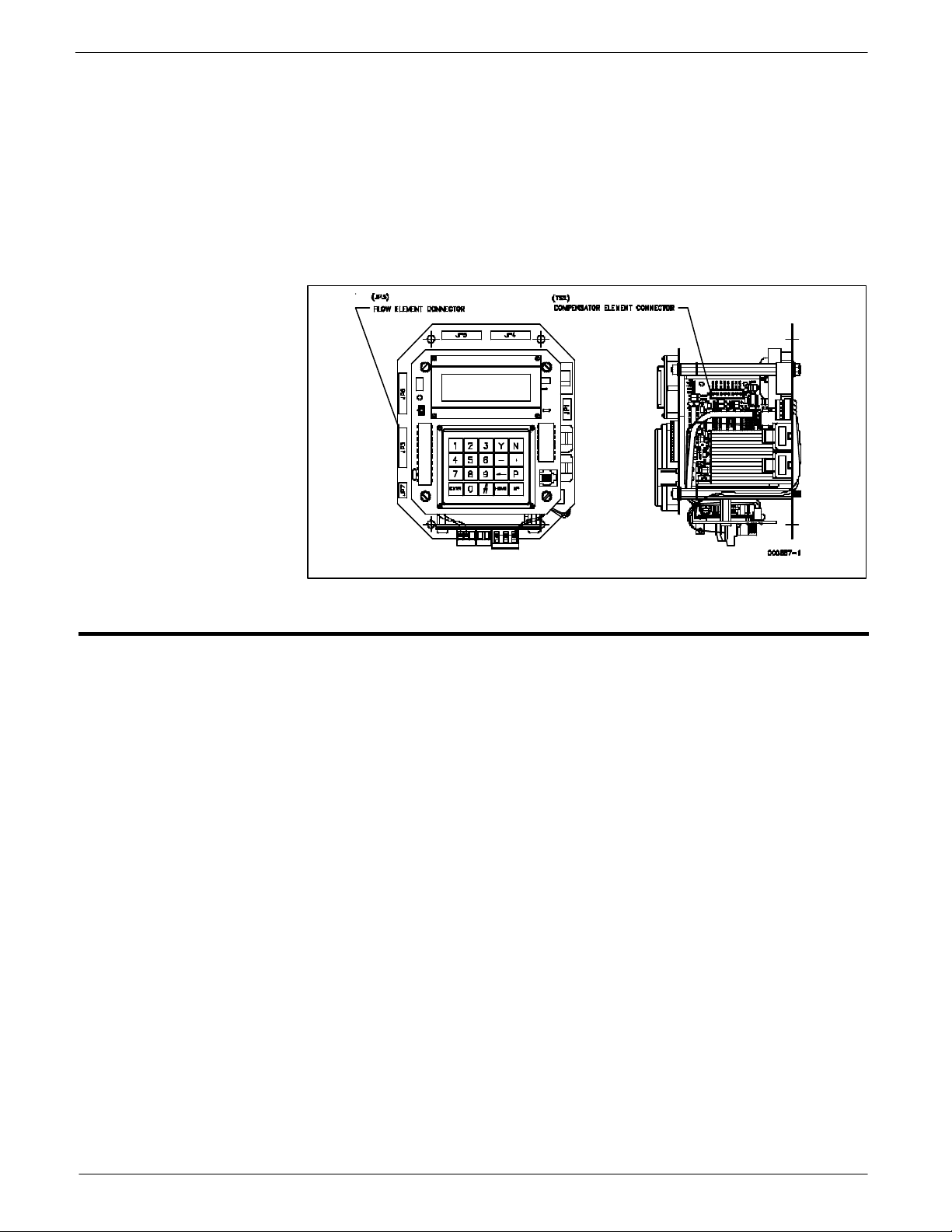
The display orientation varies for different transmitter configurations, but the termination
block for the element connection remains the same. If the Veri-Cal option was ordered,
wire the pressure transducer as shown on the wiring diagram.
Figure 5 - Electronics Assembly
Customer Wiring
Jacks JP3 (top circuit board), JP4, JP5, JP6 and JP7 are for customer use and are
described in Table 2.
JACK / NOMENCLATURE DESCRIPTION
JP3 (top circuit board)
RS-232 (EIA-232) Serial Port
JP4 Relay Output 1
and
JP5 Relay Output 2
JP6 Analog Output
Doc. No. 06EN003352 Rev. B 9 Model GF03 Flow Meter
Table 2 - Customer Wiring
Used in conjunction with equipment compatible
with an RS-232 (EIA-232) serial port. See Chapter
3 for more details.
Factory pre -programmable relay contacts. Two
normally closed contacts are available (double pole,
single throw relay) per jack. External relays can be
connected to the +EXT and -EXT pins in each jack.
Recommended relays are 18Vdc, 0.1A. max at 180
or more ohms pull i n current.
There are two factory pre -programmable signals
which are voltage and/or current. The 1 AUX and
+20V pin is a customer option for the use as a
dynamic correction factor. See Chapter 3 for more
information.
Page 14
FLUID COMPONENTS INTERNATIONAL LLC http://www.fluidcomponents.com
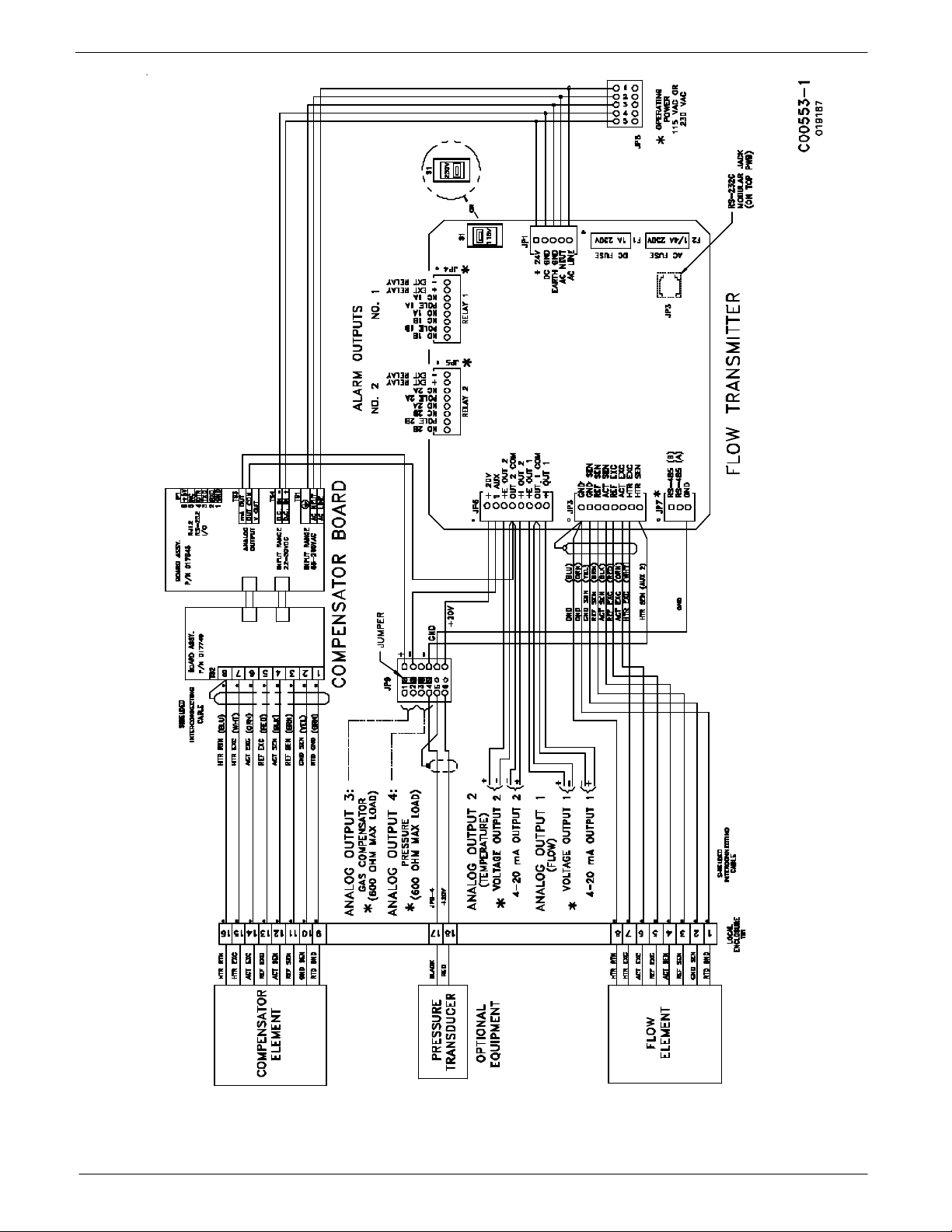
Figure 6 - Wiring Diagram, Remote with Veri-Cal
Model GF03 Flow Meter 10 Doc. No. 06EN003352 Rev. B
Page 15

FLUID COMPONENTS INTERNATIONAL LLC http://www.fluidcomponents.com
Figure 7 - Wiring Diagram, Remote
Doc. No. 06EN003352 Rev. B 11 Model GF03 Flow Meter
Page 16

FLUID COMPONENTS INTERNATIONAL LLC http://www.fluidcomponents.com
THIS PAGE INTENTIONALLY LEFT BLANK
Model GF03 Flow Meter 12 Doc. No. 06EN003352 Rev. B
Page 17

FLUID COMPONENTS INTERNATIONAL LLC http://www.fluidcomponents.com
3. Operation
Introduction
Start Up Procedure
Operation
The flowmeter has been configured and calibrated to custom specifications. Each flowmeter
contains distinct operating limits and units of measurement. This chapter will show how to
determine and manipulate the configuration of the flowmeter.
1. After the wiring has been verified, apply power to the flowmeter. (No special instructions
for instrument shutdown; turn operating power off.)
2. Then wait 10 minutes for warm-up. During this period the flowmeter may indicate high
flow.
3. After power up the instrument automatically enters the flow metering mode and the
display sets to normal operation.
Display
The flowmeter contains a 4 x 20 character LCD display. Flow rate, temperature, and system
status are all accessible through the display.
Initialization Window
When power is applied to the flowmeter the display will briefly show the initialization
window. See Figure 8.
FCI GF03
Initializing
Wait, Please
V1.00 Dec 16, 2003
Version Number and
Revision Date
C00549-1
Figure 8 - Initialization Window
Normal Mode Window
The flowmeter upon power up defaults to the normal mode of operation and begins to display
the flow rate, the temperature, the total flow (if enabled ) and the current system status. The
Normal Operation display is shown in Figure 9.
Flow Units
Temperature
Totalizer
Sample
Rate
ModeRelay
C00239-2
Output
Channel #
Flow Rate
CH1: 5056.3 SCFM
CH2: 71.2 °F
435226 SCF
Σ =
(grp1)(ed)(norm)(m)
Group #
Status
Figure 9 - Normal Operation Display
Doc. No. 06EN003352 Rev. B 13 Model GF03 Flow Meter
Page 18

FLUID COMPONENTS INTERNATIONAL LLC http://www.fluidcomponents.com
Menu Window
The menu is made up of 4 components. They are the menu level, title, selections, and prompt
line. These components are illustrated in Figure 10. The top line displays a menu code and
title. Lines 2 and 3 are used to scroll through the available selections. The prompt line
indicates which menu commands are appropriate.
Title
Menu
Level
2.1 ANALOG SETUP
1=Setup Port 1
2=Setup Port 2
UP HOME
Available
Selections
Prompt
Line
C00435-1
Figure 10 - Menu Window
The menu code is a numeric reference that identifies each window of the menu
structure. The menu code in Figure 10 indicates that the user is two levels deep
(Level 2, sublevel 1). The menu structure will be explained further in Menu
Organization.
The title gives the user a better idea of where the system is within the menu structure. Some
titles are informative enough to completely describe the menu function, while other titles are
ambiguous unless there is knowledge of the parent menus.
The middle two lines display the available selection. The number of choices is often more than
the two displayed. Pressing the N (next) or P (previous) keys on the keypad will scroll the
selections up or down. To choose a function from the available selections press the
corresponding number on the keypad.
The prompt line displays appropriate menu control key strokes for that menu level. Pressing
N, the (N)ext key, will scroll the display down. Pressing P, the (P)rv or Previous key, will
scroll the display up. Pressing the UP key shifts the current menu level up one. Pressing the
HOME key goes straight to the 0.0 MAIN MENU.
Other Window Types
Another common window encountered is shown in Figure 11. The window is similar to the
Menu Window except that it does not scroll and all choices are contained within the window.
The current selection (if there is one) is also contained in the parenthesis to the left of the
question mark.
Press the corresponding number in the Available Sections for the choice of display.
Menu Level
Current
Selection
Title
3.1.2 STD VOLUME
1 = Cu feet 2 - Cu meter
3 = Liters
(CF)s ?
C00241-1
Available
Selections
Prompt
Line
Figure 11 - Non-Scrolling Menu Window
Model GF03 Flow Meter 14 Doc. No. 06EN003352 Rev. B
Page 19
FLUID COMPONENTS INTERNATIONAL LLC http://www.fluidcomponents.com
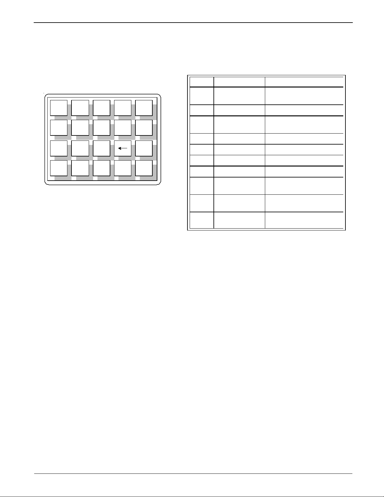
Menu Control
The prompt line displays appropriate key strokes for that menu level. If a key is pressed that
is not valid for that menu, Invalid Response will flash briefly across the prompt line. The key
pad layout is shown in Figure 12.
Key Key Name Action
1 2 3 Y N
4 5 6
7 8 9 P
ENTR
0 #
_
HOME
Figure 12 - Key Pad
See Table 3 for key pad assignments. At any time, the HOME key can be pressed and the main
menu will display. HOME can be used to escape from most routines, restart a progression into
the menu structure, or quickly change from one area of the menu to another.
When (N)ext is displayed on the prompt line, more than two menu selections are available.
Press N to scroll through all the selections.
The UP key, will back-out of a menu level. The menu moves back one level each time the UP
key is pressed. The UP key only functions when UP is displayed on the prompt line.
To make a selection, press the numeric key associated with the desired menu selection. The
selection does not have to be displayed, but it must be one of the available selections.
Every path through the menu will eventually cause control to pass from the menu structure
to a routine that performs a task such as change a parameter value, initiate a test, or calibrate
the system hardware. When the system is operating outside the menu structure, there are
subtle differences in the user interface. For example, the UP key may have no affect or the
prompt line won't appear.
.
UP
C00220-1
0 - 9 Numeric
Y Yes Enter a yes response
N No or (N)ext
- Minus Enter a minus sign
Decimal Point Enter a decimal point
Back Space Moves cursor back one space
P (P)rv or Previous Scrolls to the previous screen
ENTR Enter
HOME Home
UP Up
Selects options and enters
numbers
Enter a no response or scrolls
to the next screen
Enters a numeric value or
response
Returns to the Main Menu or
escapes from routines
Move current menu up one
level
Table 3 - Key Assignments for the GF Series Key Pad
Doc. No. 06EN003352 Rev. B 15 Model GF03 Flow Meter
Page 20

FLUID COMPONENTS INTERNATIONAL LLC http://www.fluidcomponents.com
Menu Organization
The menu structure is divided into 8 major groups. The first menu option places the flow
transmitter's display into the Normal Display mode. When the system is in this mode, flow
and temperature measurements are displayed. While in the Normal Display mode, pressing
any key will cause the main menu to display. Figure 13 shows the entire menu structure.
Menu selections two through eight allow the configuration of the flowmeter to be checked
and manipulated. Table 4 summarizes the functions contained in each menu group.
Group Name Function
2.0 Port Setup
Sets analog outputs, set relay switch point and
configure the auxiliary input.
Sets the units of measure for the displayed flow
3.0 Display Setup
rate, temperature and total flow. Sets the sample
rate.
4.0 Miscellaneous
Sets the current calibration group. Configures
the Corrector. Sets the user password.
5.0 Verify Displays system variables to the screen.
6.0 Diagnostics Factory use only.
7.0 Calibration Displays Delta R in ohms.
8.0 Normalize Board Factory use only.
The Port Setup, Display Setup and Miscellaneous groups is where most activity is concentrated.
The Verify, Diagnostics, Calibration and Normalize Board groups are used primarily for
diagnostics and factory calibration.
Normal Operation
The flowmeter upon power up defaults to this mode. During normal operation the flow rate
and the temperature is displayed. The total flow is displayed if it is enabled and few system
configuration parameters are shown. Figure 9 is the Normal Operation display.
The first and second lines contain the current flow rate and temperature. The total flow is
displayed on the third line only if it is enabled. The last line contains the current Group
number (see the Multiple Groups section in Advanced Features), the relay status, the mode
of operation and the sample rate.
The relays status shows either e (energized) or d (de-energized). The letters correspond to
the first and second relays, respectively. The mode of operation is norm for normal, auto for
Auto-Select or link for Link Groups. (See Advanced Features for explanation of these
modes). The sample rate is slow (s), medium (m) or fast (f).
Table 4 - Menu Functions
Model GF03 Flow Meter 16 Doc. No. 06EN003352 Rev. B
Page 21

FLUID COMPONENTS INTERNATIONAL LLC http://www.fluidcomponents.com
0.0 MAIN MENU
1 = Normal Operation
2 = Port Setup
3 = Display Setup
4 = Miscellaneous
5 = Verify
6 = Diagnostics
7 = Calibration
8 = Normalize Board
2.0 PORT SETUP
1 = Analog Output
2 = Relays
3 = Comm Output
4 = Aux Input
3.0 DISPLAY SETUP
1 = Flow Setup
2 = Temperature Setup
3 = Totalizer Setup
4 = Sample Rate
4.0 MISCELLANEOUS
1 = Set Group
2 = Corrector Setup
3 = Password Setup
5.0 VERIFY
1 = All
2 = Flow
3 = Totalizer
4 = Area
5 = Temperature
6 = Ports
7 = Relay
8 = Calibration
9 = Corrector
2.1 ANALOG SETUP
1 = Setup Port 1
2 = Setup Port 2
2.2 RELAY SETUP
1 = Setup Relay 1
2 = Setup Relay 2
3 = Test Relays
2.3 COMM PORT OUTPUT
1 = Set PC/Handheld
2 = Set 485 Address
2.4 AUX INPUT
1 = Enable/Disable
2 = Enter Aux.
3 = Test Input
4.1 SET GROUP
1 = Set Group
2 = Set Auto-Select
3 = Enable Auto-Select
4.2 CORRECTOR SETUP
1 = Enable/Disable
2 = Enter Corr
3 = Verify Corr
4.3 PASSWORD SETUP
1 = Enable/Disable
2 = Edit Password
CH1: 5056.3 SFCM
CH2: 71.2 F
Σ = 435226 SCF
(grp1) (dd) (mode N) (m)
Normal Operation
3.1 FLOW SETUP
1 = Mass
2 = Std Volume
3 = Velocity
3.2 TEMP SETUP
1 = Set Temp Units
2 = Set TCal Add
3 = Set TCal Mult
4 = Verify
3.3 TOTALIZER SETUP
1 = Enable/Disable
2 = Flow Units
3 = Reset
4 = Verify
5 = Totalizer Prescale
6 = Display Group Summ
7 = Aggregate Tot Mode
6.0 DIAGNOSTICS
1 = Output Tests
2 = Circuit Tests
7.0 CALIBRATION
1 = Show Delta R
2 = Show Raw Data
3 = Set Calibration
4 = Veri-Cal
8.0 NORMALIZE BOARD *
1 = Set Heater
2 = Set ACT/REF
3 = Set Outputs
4 = Board Version
5 = Set Defaults
* Requires Factory Password
7.3 SET CALIBRATION
1 = Set Coeff Group
2 = Set Sensor Type
3 = Set Flow Coeff's
4 = Set Temp Coeff's
5 = Standard Density
6 = Set Limits
7 = Link Groups
8 = Verify
6.2 CIRCUIT TESTS
1 = Gain
2 = Temp
3 = TA/D Mode
4 = Switches
5 = Heater Current
8.3 SET OUTPUTS
1 = Calibrate Outputs
2 = Test Outputs
MENU 11-17-03.VSD
Figure13 - Menu Structure
Doc. No. 06EN003352 Rev. B 17 Model GF03 Flow Meter
Page 22

FLUID COMPONENTS INTERNATIONAL LLC http://www.fluidcomponents.com
Quick Operation Procedure
Input power is the only thing needed to operate the instrument. If a modification to the factory
setup is needed then continue with this section.
In order to use Table 5, an assumption has been made that the password is enabled (this is the
factory preset condition).
For proper operation of the flowmeter all the information in the Analog Output category needs
to be entered as a group, also all of the information in the Flow Rate Units category needs to
be entered (do not skip steps).
If mistakes in data entry are made, press the back arrow key to correct the mistake.
Table 5 - Quick Operation Procedure
Function Desired * Keys to Press ** Comments
Main Menu Press any key
Main Menu Press OME THEN 1
(1) NORMAL
OPERATION
SET PASSWORD
(1) Enable / Disable
Press HOME then 1 To get the normal display.
Press HOME, 4, 3, 1. Then
enter user password. Then press
ENTR, HOME
To get from the normal display to the
main menu.
To get from other menus to the main
menu in most cases. In some cases
(when shown) press ENTR. Then
HOME.
The factory recommends that the
password be disabled before any
information is entered to speed up the
process. (Default password: 123)
PORT 1: MODE
(1) 4-20mA (2) 0-5V
(3) 1-10V (4) 1-5V
PORT 1: UNIT
(1) FLOW (2)
TEMP
PORT 1: F.S.
PORT 1: ZERO
PORT 2: MODE
(1) 4-20mA (2) 0-5V
(3) 1-10V (4) 1-5V
PORT 2: UNIT
(1) FLOW (2)
TEMP
ANALOG OUTPUTS
Press HOME, 2, 1, 1, 1. Then 1
or 2 or 3 or 4 or ENTR. Then 5,
Y or N. HOME
Press HOME, 2, 1, 1, 2. Then 1
or 2. Then 5, Y or N, HOME
Press HOME, 2, 1, 1, 3. Then
press in a numeric value. Then
press ENTR, 5, Y or N, HOME
Press HOME, 2, 1, 1, 4. Then
press in a numeric value. Then
press ENTR, 5, Y or N, HOME
Press HOME, 2, 1, 2, 1. Then 1
or 2 or 3 or 4 or ENTR. Then 5,
Y or N. HOME
Press HOME, 2, 1, 2, 2. Then 1
or 2. Then 5, Y or N, HOME
Press the key that best matches the
analog input to the peripherals from
Jack JP6 of the Flow Transmitter. Press
ENTR only if previous values are
correct.
Press the key that matches the
condition to be measured.
Enter the numeric full-scale value that
is expected to occur. The value needs
to be between the values shown on the
second and third lines of the display.
Press ENTR without inputting a
numeric value only if previous values
are correct.
Enter the numeric zero scale value that
is expected to occur. The value needs
to be between the values shown on the
second and third lines of the display.
Press ENTR without inputting a
numeric value only if previous values
are correct.
Press the key that best matches the
analog to the peripherals from Jack JP6
of the Flow Transmitter. Press ENTR
only if previous values are correct.
Press the key that matches the
condition to be measured.
Model GF03 Flow Meter 18 Doc. No. 06EN003352 Rev. B
Page 23

FLUID COMPONENTS INTERNATIONAL LLC http://www.fluidcomponents.com
Table 5 - Quick Operation Procedure
Function Desired * Keys to Press ** Comments
Enter the numeric full-scale value
that is expected to occur. The value
needs to be between the values
shown on the second and third lines
of the display. Press ENTR without
inputting a numeric value only if
previous values are correct.
Enter the numeric zero scale value
that is expected to occur. The value
needs to be between the values
shown on the second and third lines
of the display. Press ENTR without
inputting a numeric value only if
previous values are correct.
PORT 2: F.S.
PORT 2: ZERO
Press HOME, 2, 1, 2, 3. Then
press in a numeric value. Then
press ENTR, 5, Y or N, HOME
Press HOME, 2, 1, 2, 4. Then
press in a numeric value. Then
press ENTR, 5, Y or N, HOME
FLOW RATE UNITS
MASS UNITS
(1) LB (2) KG
(3) TNS
Std Volume
(1) Cu Feet (2) Cu Meter
(3) Liters
Std Velocity
SET PASSWORD
(1) Enable / Disable
* NUMBERS IN PARENTHESIS ARE KEYS TO BE PRESSED
** Y = SAVE PERMANENTLY OR N = DO NOT SAVE
Press HOME, 3, 1, 1. Then 1 or 2
or 3, then in the TIME UNITS
menu press 1 or 2 or 3 or 4, then
in the AREA menu press 1 or 2,
then 1 or 2 or 3 or 4. Then enter a
numeric value. Press ENTR, any
key, any key, Y or N, HOME.
Press HOME, 3, 1, 2. Then 1 or 2
or 3, then in the TIME UNITS
menu press 1 or 2 or 3 or 4, then
in the AREA menu press 1 or 2,
then 1 or 2 or 3 or 4. Then enter a
numeric value. Press ENTR, any
key, any key, Y or N, HOME.
Press HOME, 3, 1, 3. Then in the
LENGTH UNITS menu press 1
or 2. In the TIME UNITS menu
press 1 or 2 or 3 or 4, then any
key, Y or N, HOME.
Press HOME, 4, 3, 1 then HOME
Enter the flow rate, using the
necessary mass units needed along
with the units per time and the pipe
diameter or area. ENTR can be
used if the values are already
correct.
Enter the standard volume in Cubic
Feet, Cubic Meters, or Liters along
with the units per time and the pipe
diameter or area. ENTR can be
used if the values are already
correct.
Enter the standard velocity in feet
or meters per unit time.
The factory recommends the
password be enabled with this step
after the above information has
been completed.
Doc. No. 06EN003352 Rev. B 19 Model GF03 Flow Meter
Page 24

FLUID COMPONENTS INTERNATIONAL LLC http://www.fluidcomponents.com
Configuring the
Flowmeter
There are several parameters that can be modified to customize the system. This section
describes how the flowmeter can be customized to best fit requirements.
Password Protection
Before the flowmeter configuration is customized, access to the system parameters must be
gained. Two levels of password protection affect access to these parameters.
w Factory Level
The highest level of protection requires a system password for access. This password
prevents the user from inadvertently changing variables associated with the system
calibration or other parameters that require factory resources to properly set.
w User Level
The second level of protection requires a user password for access. This password
provides the user with the ability to limit access to parameters that affect the way the
system operates. The default user password is 123 and can be changed to any combination
of up to 12 characters in length.
Both levels of password protection can be enabled or disabled. When the system leaves the
factory, the factory level and user passwords are enabled. No password is required to enable
a level of protection, but the appropriate password is required to disable protection.
NOTE:
w To edit the user password:
1. From the Main Menu press 4. The 4.0 MISCELLANEOUS menu title will appear.
2. Press 3, Password Setup.
3. Press 2, Edit Password.
4. If password protection is enabled enter the current password.
5. Enter the new password of up to 12 characters.
6. When prompted to Save Permanently enter Y for yes.
The user password is set to 123 when the system is shipped.
Selecting
Units of Measure
w To enable and disable the password protection:
1. From the Main Menu press 4. The 4.0 MISCELLANEOUS menu title will appear.
2. Press 3, Password Setup.
3. Press 1, Enable/Disable Password.
4. Enter the user password if prompted to do so.
5. The password protection will be toggled on or off depending on its previous state.
The flowmeter measures the flow rate and stream temperature of the process media. The
display can be set to present the flow rate and temperature in a variety of units. The factory
will set the units of measure to those specified at order entry time. There are other units of
measure that can be chosen. Two units that will appear are m and mm. The letter m stands for
1000 and mm stands for 10,000. Menu level 3.1 provides the options for changing the output
units of measure. The units of measure can be selected for temperature at menu level 3.2. The
units of measure for the totalizer are available at menu level 3.3.
NOTE:
By answering the prompt, Save permanently?, with a N or by pressing the HOME
key, the flowmeter will revert to the previously saved units of measure when the
power is cycled.
Model GF03 Flow Meter 20 Doc. No. 06EN003352 Rev. B
Page 25

FLUID COMPONENTS INTERNATIONAL LLC http://www.fluidcomponents.com
w To choose a new unit of measure for flow rate:
1. From the Main menu press 3. The 3.0 DISPLAY SETUP menu title will appear.
2. Press 1, the Flow Setup option.
3. At this point there are three choices, Mass, Std Volume and Std Velocity. Table 6
summarizes the choices contained in Mass, Std Volume and Std Velocity.
4. By pressing 1, 2, or 3, the display will prompt the user to enter the user password (if it is
enabled) and then the respective mass, volume or length units from Table 6. Enter the
desired measurement type. For example, pressing 1 will show the following display:
1=LB, 2=KG or 3=TNS.
5. Enter the desired time units, seconds, minutes, hours or days.
6. If Mass or Std Volumetric units have been selected, enter the pipe cross-sectional area.
There is the option of entering the area directly or, for circular pipes, entering the inside
diameter.
7. Enter the desired area units.
8. Enter the pipe area or the pipe inside diameter. Press any key twice.
9. When prompted to Save permanently enter Y for yes.
NOTE:
The term Std refers to standard or standard conditions. Standard volume refers to
the space a gas occupies at a defined pressure and temperature. The factory uses
14.7 psia and 70°F as its standard conditions. Std Velocity is defined as the
standard volumetric flow rate divided by the pipe cross-sectional area.
Table 6 - Flow Rate Units of Measure
Selection Units Description
LB/Time
Mass
Std Volume
Std Velocity
w To choose a new unit of measure for temperature:
KG/Time
TNS/Time
SCF/Time
NCM/Time
NL/Time
SF/Time
NM/Time
Pounds per Unit time. Time units are seconds, minutes, hours or days.
Kilograms per unit time.
Metric Tonnes (1000 Kilograms) per unit time.
Standard Cubic Feet per unit time.
Normal Cubic meters per unit time.
(Normal is the metric equivalent of Standard.)
Normal liters per unit time.
Standard feet per unit time.
Normal meters per unit time.
1. From the Main menu press 3. The 3.0 DISPLAY SETUP menu title will appear.
2. Press 2, the Temperature Setup option.
3. Press 1 to change the units for temperature.
4. After entering the user password (if it is enabled) there will be 4 choices: (°F) degrees
Fahrenheit, (°C) degrees Celsius, (K) Kelvin and (R) Rankine. Press the appropriate
number corresponding to the desired temperature units.
5. When prompted to Save permanently enter Y for yes.
Doc. No. 06EN003352 Rev. B 21 Model GF03 Flow Meter
Page 26

FLUID COMPONENTS INTERNATIONAL LLC http://www.fluidcomponents.com
w To choose a new unit of measure for total flow:
1. From the Main menu press 3. The 3.0 DISPLAY SETUP menu title will appear.
2. Press 3, the Totalizer Setup option.
3. Press 2, Flow Units, to change the units for total flow.
4. There is the option of standard volumetric units or mass units. See Table 6 for a
description of the available choices. Press 1 or 2.
5. After entering the user password (if it is enabled) the user will be prompted with
standard volumetric or mass units. Enter the desired total flow units.
6. The user will be prompted to enter the pipe cross-sectional area. The user has the
option of entering the area directly or, for circular pipes, entering the inside
diameter. Enter the method desired.
7. Enter the desired area units.
8. Enter the value of the pipe area or the pipe inside diameter. Press any key twice.
9. When prompted to Save permanently enter Y for yes.
w To choose Totalizer Prescaler for total flow:
1. From the Main menu press 3. The 3.0 DISPLAY SETUP menu title will appear.
2. Press 3, the Totalizer Setup option.
3. Press 7, Totalizer Prescaler, to change between prescale values of 0, .001 or 1000.
4. Press 0 for no prescale, or press 1 for a prescale value of .001, or press 2 for a prescale
value of 1000.
In this mode the totalizer will be displayed with a fixed decimal place.
w To choose Display Group Sum for total flow:
1. From the Main menu press 3. The 3.0 DISPLAY SETUP menu title will appear.
2. Press 3, the Totalizer Setup option.
3. Press 8, the Display Group Sum.
The totalized flow for the first group will be displayed. Pressing any key will display
the totalized flow for the second group if the second group is enabled. Pressing any
key will display the totalized flow for the third group if the third group is enabled.
The group totals will be displayed regardless if they have been initialized. These
values can be reset by switching to each group and individually resetting each one or
doing a reset all from menu 3.3.3.
w To choose Aggregate Tot Mode for total flow:
1. From the Main menu press 3. The 3.0 DISPLAY SETUP menu title will appear.
2. Press 3, the Totalizer Setup option.
3. Press 9, Aggregate Tot Mode, to turn on or off the aggregate total mode.
This setting is saved in EEPROM and recalled when the system is reset. When the
aggregate mode is enabled, the following parameters must be the same for all the
groups that are linked; totalizer prescale, and the totalizer units. If all the parameters
do not match, the totalizer display will show "AGGREGATE TOT ERROR".
Model GF03 Flow Meter 22 Doc. No. 06EN003352 Rev. B
Page 27

FLUID COMPONENTS INTERNATIONAL LLC http://www.fluidcomponents.com
Setting Analog Outputs
The flowmeter has two, independent analog signal outputs. The outputs can be set to represent
flow rate or temperature. The flowmeter signal outputs have been configured according to the
application information supplied to the factory at the time of order. However, the outputs can
be re-scaled anywhere within the calibrated flow range. The ouputs can be independently set
to one of the four ranges: 4 to 20 mA, 0 to 5 V, 0 to 10 V, or 1 to 5 V. A typical configuration
is presented in Table 7.
The signal range varies linearly with change in flow rate as shown in Figure 14. Minimum
Port No. Mode Type Zero Full-Scale (F.S.)
1 4 to 20mA Flow 0 SF/S 150 SF/S
2 4 to 20mA Temp -50°F 150°F
Table 7 - Typical Signal Output Configuration
signal output can be set to indicate a flow of zero. This is often referred to as a zero-based
signal output. A minimum signal that represents a value greater than zero is referred to as nonzero based.
Figure 14 - Signal Output versus Flow Rate
NOTE: The flowmeter inherently has a minimum, non-zero flow rate that it is able to
detect. Therefore, setting the minimum signal output (referred to as Zero in Menu
2.1.1) to zero will create a step in the output. This step corresponds to the flow
where the flowmeter begins accurate measurement. Turndown ratios ( turndown
is defined as the maximum flow rate divided by the minimum flow rate) smaller
than 10:1 will have a large step change thus reducing the usable signal range.
Doc. No. 06EN003352 Rev. B 23 Model GF03 Flow Meter
Page 28

FLUID COMPONENTS INTERNATIONAL LLC http://www.fluidcomponents.com
w To re-scale the signal outputs:
1. From the Main menu press 2. The 2.0 PORT SETUP menu title will appear.
2. Press 1, the Analog Output option.
3. Press 1 or 2, corresponding to the analog port to be re-scaled.
4. After entering the user password (if it is enabled), press 1 to change the analog
output mode. Select the signal mode. (The current selection is shown in
parenthesis to the left of the question mark.)
5. Press 2 to change the analog output type. Press 1 for an output signal based on
flow. Press 2 for an output signal based on temperature.
6. Press 3 to change the maximum or Full Scale (F.S.) flow rate. Enter a maximum
flow rate value within the specified range.
7. Press 4 to change the zero flow rate. Enter a minimum flow rate value within
the specified range. A value of zero is valid.
8. Press 5 to save and exit to the previous menu level. Press Y when asked to save
permanently.
There are two double pole, double throw relays on the flowmeter. They can be set to
respond to changing flow rates or changing temperatures.
There are four types of switching schemes to choose from. These are referred to as Above,
Below, Outside, and Inside. Each switch point can be set to have hysteresis and a time delay.
Figure 15 illustrates the four switch point schemes with arbitrary hysteresis assigned.
Switching schemes, Above and Below change relay states when the flow or temperature
Setting the Relays
crosses the switch point value. The outside and inside schemes contain a range wherein the
relay changes states.
Flow
or
Temperature
ON
OFF
Above
Switch point
Deactivation
OFF
Below
ON
OFF
Outside
}
ON
Hysterisis
Figure 15 - Relay Switch Point Schemes
OFF
ON
Inside
C00225-2
Model GF03 Flow Meter 24 Doc. No. 06EN003352 Rev. B
Page 29

FLUID COMPONENTS INTERNATIONAL LLC http://www.fluidcomponents.com
w To set the relays:
1. From the Main menu press 2. The 2.0 PORT SETUP menu title will appear.
2. Press 2, the Relay Setup option.
3. Press 1 or 2, corresponding to the relay to be set.
4. After entering the user password (if it is enabled), press 1, Unit, to select the
switching parameter. Press 1 to switch on flow rate or press 2 to switch on
temperature. (The current selection is shown in parenthesis to the left of the question
mark.)
5. Press 2, Activate On, to select the switching scheme desired (See Figure 13). Press
1 for an Above, press 2 for Below, press 3 for Inside or press 4 for Outside.
Depending on the choice made, enter 1 or 2 switch point values. For example, if
Inside has been chosen, the user will then be prompted to enter a low range switch
point and a high range switch point. The values entered must be within the displayed
allowable range.
6. Press 3 to change the switch delay. Delay pauses the change in relay state when a
switch point is crossed. The value entered is approximately equal to seconds.
7. Press 4 to change the dead band or hysteresis of the switch point (See Figure 13). The
dead band or hysteresis has a value of flow rate or temperature depending on whether
switch on changes in flow rate or temperature have been chosen.
8. Press 5 to save and exit to the previous menu level. Press Y when asked to save
permanently.
Testing the Relays
Checking the
Current Setup
From the keypad, the relay state can be switched. This can be used to test the interface with
relays. This is also described in Chapter 5 Troubleshooting.
w To test the relays:
1. From the Main menu press 2. The 2.0 PORT SETUP menu title will appear.
2. Press 2, the Relay Setup option.
3. Press 3, for the Test Relays option.
4. Pressing 1 or 2 will toggle the states of the respective relays. The present state of the
relays are displayed in parenthesis.
The functions within menu level 5.0 provides a quick means of displaying the current
system parameters for the flowmeter. The flow rate and temperature units of measure, the
state of the analog outputs and relays or other critical information can be viewed from this
menu.
w To view the flow range, the flow rate units of measure and the area:
1. From the Main menu press 5. The 5.0 VERIFY menu title will appear.
2. Press 2, the Flow option. The sequence of information will be displayed to the screen
as shown in Figure 14. Press Enter twice to proceed. The first line of screen 1 is the
window title. Line 2, the Flow Factor is the conversion factor from the internal units
of measure (SF/S) to the desired units. Lines 3 and 4 show the flow range and the
current flow units. Screen 2 shows the standard density of the flow stream.
3. Press 4, the Area option. Screen 3, shown in Figure 14 will appear. The second line
shows the pipe area and units. The third line is the inside diameter of the pipe. (The
third line will appear only if the pipe I.D. is entered. If Std Velocity flow units are
used the Area option is not available.)
Doc. No. 06EN003352 Rev. B 25 Model GF03 Flow Meter
Page 30

FLUID COMPONENTS INTERNATIONAL LLC http://www.fluidcomponents.com
FLOW
Flow Factor: 5.30
0.530 to 1591
SCFM
Window 1 Window 2
Figure 16 - Flow and Area Verification
NOTE: The flowmeter does not measure standard density. This number is entered through
menu level 7.3.5. The standard density displayed in menu 5.2 must be equivalent
to the standard density of the process media. The factory has entered the process
standard density supplied at the time of order. The standard density factor is only
used when calculation mass flow units.
w To view the temperature and totalizer units of measure:
1. From the Main menu press 5. The 5.0 VERIFY menu title will appear.
2. Press 5 to view the current units for temperature. Press 3 to view the current units for
the total flow. (If the totalizer is disabled the display will only show No Totalizer.)
The information will be displayed to the screen as shown in Figure 17.
TEMPERATURE:
Temp units: °F
FLOW
Standard Density:
0.07497 LBM/FT3
SCF
AREA/PIPE I.D.
Area = 12.73 sq in
I.D.=4.026 in
HIT anykey to EXIT
Window 3
C00243-1
Totalizer Units:
Tcal Add = 0.000
Tcal Mult = 1.000
HIT any key to EXIT
Window 1 Window 2
C00244-1
Figure 17 - Temperature, Totalizer Verification Display
Line 2 of screen 1 shows the current units for temperature. Lines 3 and 4 display the offset
and multiplier to the measured temperature. See Advanced Features for a detailed explanation.
Screen 2 shows the total flow units.
w To view the analog output parameters:
1. From the Main menu press 5. The 5.0 VERIFY menu title will appear.
2. Press 6, the Ports option. The two screens in Figure 18 are identical except for the
port number. Line 2 is the current signal output mode. Line 3 shows the full scale
flow rate or temperature value and the appropriate units. Line 4 is the zero value.
Press any key for screen 2.
PORT 1
Mode: 4-20 mA
F.S. : 1591 SCFM
ZERO: 0.00 SCFM
Mode: 4-20 mA
F.S. : 150 °F
ZERO: -50 °F
Window 1 Window 2
Figure 18 - Analog Output Verification
PORT 2
C00245-1
Model GF03 Flow Meter 26 Doc. No. 06EN003352 Rev. B
Page 31

FLUID COMPONENTS INTERNATIONAL LLC http://www.fluidcomponents.com
w To view the relay switching parameters:
1. From the Main menu press 5. The 5.0 VERIFY menu title will appear.
2. Press 7, the Relay option. The two screens in Figure 19 describe how the two relays
will react to changes in flow rate or temperature. Screen 1, line 1 is the current status
of relay 1. Line 2 shows that the relay will change states when the flow rate exceeds
100 SCFM. The last line displays a hysteresis (H) of 5 SCFM and a delay of about
3 seconds. Screen 2, line 1 is the current status of relay 2. Line 2 and 3 shows that
the relay will switch states on changes in temperature (°F). The state of the relay will
change when the temperature is inside the temperature range of -50 to 150 °F. The
last line displays a hysteresis (H) of 2 °F and a delay of about 1 second.
Advanced Features
RELAY 1: OFF
Above 100 SCFM
RELAY 2: ON
°F (Inside)
-50 to 150
H: 5.00 D: 3.00
Window 1 Window 2
Figure 19 - Relay Staus Verification Display
The remainder of this chapter contains topics that may not be applicable to every user of the
flowmeter. In most cases the flowmeter will be ready for use straight out of the box. However,
there may be an application where the advanced features of the flowmeter may be needed.
This section discusses how to correct for bias errors due to non-ideal installations, how to
communicate with the flowmeter through the serial port, and how to use the multiple
calibration options.
Flow Rate Correction Equation
The flow rate correction equation or corrector is used to bias the flow rate output. The
correction equation contained in the flowmeter allows the user to correct for bias errors due
to non-ideal installation effects. The correction equation is applied to the measured flow rate
and then this corrected flow rate is used to drive the analog outputs and manipulate the relays.
The flow rate shown on the display is also the corrected value. Figure 20 describes how the
correction equation is applied.
The correction equation for the flowmeter is shown below.
H: 2.00 D: 1.00
C00246-1
m
= F1 + (F2 x mo )+ (F3 x m
new
2
)+( F4 x m
o
3
)
o
where mo = Measured Flow Rate
Fi = Correction Equation Coefficients (
m
= Corrected Flow Rate
new
Doc. No. 06EN003352 Rev. B 27 Model GF03 Flow Meter
= 1 through 4 )
i
Page 32

FLUID COMPONENTS INTERNATIONAL LLC http://www.fluidcomponents.com
C00248-1
Measured flow
rate
Is the
correction
equation
Yes
Apply correction
equation
enabled?
NO
Corrected flow rate
Apply other
corrections (see
Aux. Input)
Manipulate
analog outputs
and relays
C00247-2
Figure 20 - Correction Factor
Application fo the correction equation will be illustrated in the following example. Through
analysis of the process flow stream it is determined that the flow rate must be multiplied by
1.056 to output the desired value.
The correction equation takes the following form:
m
= 0 + (1.056 x mo) + (0 x m
new
Therefore m
= 1.056 x m
new
o
o
2
)+ (0 x m
3
)
o
Where F1 = 0
F2 = 1.056
F3 = 0
F4 = 0
A more complicated situation would be where the multiplication factor varies with flow rate.
Figure 21 shows the variation of desired flow rate versus the measured flow rate.
50
40
Desired
Flow Rate
30
20
10
0
0 20 40 60
Measured Flow Rate
Figure 21 - Desired Flow Rate versus Measured Flow Rate
Model GF03 Flow Meter 28 Doc. No. 06EN003352 Rev. B
Page 33

FLUID COMPONENTS INTERNATIONAL LLC http://www.fluidcomponents.com
The relationship between the measured and the desired flow rates was determined through a
least squares analysis. The coefficients for the above relation are:
F1 = -7.5672 F2 = 2.09253
F3 = -0.037082 F4 = 0.0003505
w To enter the correction equation coefficients and to enable it:
1. From the Main menu press 4. The 4.0 MISCELLANEOUS menu title will appear.
2. Press 2, the Corrector Setup option.
3. Press 2, the Enter Corr option, to enter the Correction Equation coefficients
4. Enter the user password (if it is enabled). Press 1 to enter the coefficient F1. Press
2 for F2 and so on to F4. Press 5 to verify the entries.
5. Press 6 to exit.
6. Press 1 to enable to Corrector. (To disable the Corrector press 1 again.)
The Auxiliary Input
The flowmeter has one analog signal input port that can be used to directly manipulate the flow
rate output. This signal input port is called the auxiliary input. The signal measured by the
flowmeter allows for the correction of errors that may be caused by changes such as process
composition. The factory has determined from the application data supplied at the time of
order whether the flowmeter would benefit from using the auxiliary input. If the auxiliary
input is not used in the flowmeter the following section can be skipped. If the auxiliary input
is used, all the internal settings necessary have been entered into the flowmeter. The following
is a description of the internal and external workings of the auxiliary input.
w To determine if the flowmeter is set to use the auxiliary input:
1. From the Main menu press 2. The 2.0 PORT SETUP menu title will appear.
2. Press 4, the Aux Input option.
3. Press 2, the Enter Aux option. Enter the user password (if it is enabled).
4. Press 5, the Verify option. The variables AUX 1, 2 and 3 will appear.
5. Press ENTR and DISABLED or ENABLED will be on the third line. If ENABLED
is displayed then the flowmeter has been configured to use the auxiliary input.
The auxiliary input is accessed at terminal JP6 located on the lower circuit board. Figure 22
illustrates the auxiliary input connected to a current source. If OUT 1 COM is not easily
accessible then use JP6 OUT 2 COM, JP7 GND, JP1 DC GND OR JP3 GND. They are
electrically the same signal ground point. The range of this source is most likely 4-20mA.
+20V
JP6
1 AUX
+E OUT 2
OUT 2 COM
+I OUT 2
+E OUT 1
OUT 1 COM
+I OUT 1
C00249-1
Figure 22 - Auxiliary Input Wiring Diagram
Doc. No. 06EN003352 Rev. B 29 Model GF03 Flow Meter
Page 34

FLUID COMPONENTS INTERNATIONAL LLC http://www.fluidcomponents.com
The flowmeter measures the applied current input, converts it to a digital value and makes a
correction to the measured flow rate. The corrected flow rate is used to drive the analog
outputs and manipulate the relays. The flow rate shown on the display is also the corrected
value. Figure 23 charts the process.
The auxiliary input port monitors the signal input level and converts it to a digital value. This
digital value can be displayed from menu level 2.4.3, the Auxiliary Test Input function.
DR
Aux Input
Enb
NO
DR
= DR
corr
Flow = f (DR
YES
) Aux Input
corr
Mode = DR?
NO
Enb
NO
Flow corr = Flow
Output
Flow
corr
DR
YES
YES
= KA DR
corr
NO
Mode = Flow ?
Flow corr = K
C00548-1
YES
A
Flow
Figure 23 - Auxiliary Input Process
w To view the digital representation of the current input:
1. Apply a current to the auxiliary input as shown in Figure 22.
2. From the Main menu press 2. The 2.0 PORT SETUP menu title will appear.
3. Press 4, the Aux Input option.
4. Press 3, the Test Input option. The digital representation of the current input is
displayed on the second line.
The approximate relationship between current input and the digital value displayed in menu
level 2.4.3 is:
Digital Value = Current Input x 51.1
The digital value is used to manipulate the measured flow rate. This digital value is used to
calculate a factor that is multiplied by the measured flow rate. The factor is calculated using
the following relationship:
KA = A1 + (A2 x s) + (A3 s2) + (A4 x s)
where s = Digital Value
Ai = Correction Factor Coefficients ( i = 1 through 4 )
KA = Correction Factor
NOTE: Ai is used for clarity in the manual. The flowmeter uses Fj as the Correction Factor
Coefficient.
The Auxiliary Input Equation coefficients are determined by the factory from the data
supplied at the time of order entry.
Model GF03 Flow Meter 30 Doc. No. 06EN003352 Rev. B
Page 35

FLUID COMPONENTS INTERNATIONAL LLC http://www.fluidcomponents.com
Serial
Communications
The flowmeter has one RS-232 port. The data stream is sent at a rate of 9600 baud with no
parity, 8 bit characters and 1 stop bit. The baud rate is fixed and cannot be changed. All
operations accessible through the keypad are also available through the serial port. The serial
port, designated as JP3, is located on the lower right corner of the upper circuit board. The
connection is a RJ-11 phone jack. Figure 24 represents the connection between the serial port
and the host device.
A serial communications kit containing adapter plugs are available from FCI for both the DB9 and DB-25 connectors which allow the use of standard 6 wire phone line cord between the
RJ-11 serial port and the host device. The order number for the DB-9 Connector kit is 014108-
01. Serial communication software is provided with each connector.
NOTE: The standard phone line used must be a reversing type and not a straight-through
type of cable.
GF Series Serial Port
RJ-11 Phone Jack
6
5
4
3
2
1
+5V
NC
DTR
TXD
RXD
GND
RJ-11 Pin
Description
1
2
3
4
5
6
RJ-11 Pin
Description
IBM PC
DB-9 Connector
DCD
DTR
TXD
RXD
GND
IBM PC
DB-25 Connector
1
4
3
2
5
Data Carrier Detect
Data Termial Ready
Transmit Data
Receive Data
Ground
+5V
NC
DTR
TXD
RXD
GND
1
2
3
4
5
6
DCD
DTR
TXD
RXD
GND
Data Carrier Detect
20
Data Termial Ready
8
Transmit Data
3
Receive Data
2
Ground
7
C00251-1
Figure 24 - Wiring Diagram, DB-9 an DB-25 PC Connectors
The serial port input/output stream duplicates the actions of the keypad and the LCD display.
Commands sent through the serial port to manipulate the flowmeter are exactly equivalent to
the keypad sequences. Data coming out of the serial port is equivalent to the data sent to the
display. Remote communication with the flowmeter consists of character sequences that
duplicate actions taken at the keypad. For example, the string H 2 4 2 5 produces the same
results as pressing HOME, 2, 4, 2, 5 from the keypad. Figure 25 is an example of code written
in Quick Basic that extracts the flow rate and the temperature through the serial port.
A common communication problem is over writing flowmeter serial buffer. If the buffer is
overwritten the last characters sent are lost. If the flowmeter does not respond as expected
to a command, slow down the data flow from the user PC or control device.
Doc. No. 06EN003352 Rev. B 31 Model GF03 Flow Meter
Page 36

FLUID COMPONENTS INTERNATIONAL LLC http://www.fluidcomponents.com
' Serial Communication example
' Fluid Components Intl
' This program places the flowmeter into normal
' operation and displays the current flow rate and
' temperature.
DEFINT A-Z
ON ERROR GOTO error.trap
COLOR 7, 1 ' Set screen color.
CLS
Quit$ = CHR$(0) + CHRS$(16) ' Value returned by INKEY$
' when ALT+q is
pressed.
' Set up screen and turn cursor off.
LOCATE 24, 1, 0
PRINT STRING$(80, "_");
LOCATE 25, 1
PRINT TAB(30); "Press ALT+q to quit";
VIEW PRINT 1 TO 23 ' Print between lines 1 & 23.
' Open communications (9600 baud, no parity, 8-bit data,
' 1 stop bit, 256-byte input buffer):
OPEN "COM1:9600,N,8,1,RS,CS,DS,CD,OP10000,RB2000" FOR RANDOM AS
#1 LEN =512
PRINT#1, "H"; ' Send a HOME command.
(Send ' another
also.)
x! = TIMER ' Wait for response. (A long
DO UNTIL TIMER - x! 3 ' wait is not necessary after
LOOP ' most commands.)
PRINT #1, "H"; ' Send another HOME
command
x! = TIMER ' Wait again
DO UNTIL TIMER - x! 3
LOOP
PRINT #1, "1"; ' Normal Operation
DO ' Main communications loop.
KeyInput$ = INKEY$ ' Check the keyboard.
IF KeyInput$ = Quit$ THEN ' Exit the loop if the user
EXIT DO ' PRESSED alt+q.
END IF
GFINPUT$ = "" ' Empty the two working
moreGFInput$ = "" 'strings
Figure 25 - Series Serial Communication Code Example
Model GF03 Flow Meter 32 Doc. No. 06EN003352 Rev. B
Page 37

FLUID COMPONENTS INTERNATIONAL LLC http://www.fluidcomponents.com
IF NOT EOF(1) THEN
' LOC(1) gives the number of characters waiting.
GFInput$ = GFInput$ + INPUT$ (LOC(1), #1)
' Gather at least one full display of information
IF INSTR(GFInput$, "CH1:") THEN
DO UNTIL INSTR(more GFInput$, "CH:")
moreGFInput$ = moreGFInput$ + INPUT$(LOC(1), #1)
LOOP
GFInput$ = GFInput$ + moreGFInput$
' Parse and print the flow rate and temperature
n% = INSTR(GFInput$, "CH:")
FlowRate! = VAL(MID$(GFInput$, n% +5))
n% = INSTR(GFInput$, "CH2:")
Temperature! = Val(MID$(GFInput$, n% + 5))
PRINT FlowRate!, Temperature!
END IF
Multiple Groups
END IF
LOOP
CLOSE ' End communications.
END
error.trap:
RESUME NEXT
Figure 25 - Series Serial Communication Code Example Cont’d
The flowmeter is calibrated at the factory in a test stand that duplicates or models the
customer application. The calibration process produces the information needed to relate
RTD signal to an actual mass flow rate. That calibration information is entered into the
flowmeter. Information about the customer's process such as pipe inside diameter and the
process standard density is also entered. Situations exist where a pipe or duct may have two
or more distinct process flow streams or the flowmeter needs to be used in more than one
installation. The flowmeter can accommodate three sets of calibration information, therefore
it can be used to monitor multiple flow streams or used in multiple installations. Each set of
calibration information is called a Group. The factory has determined from the application
data supplied at the time of order whether the flowmeter would benefit from using multiple
Groups . If multiple Groups are not used in the flowmeter the following section can be
skipped. If multiple Groups are used, all the information necessary has been entered into the
flowmeter. However, the method and conditions that determine the current Group can be
altered.
w To determine if the flowmeter is set to use the Multiple Groups:
From the Main menu press 1. The flowmeter will enter the normal mode of operation. If the
mode on the last line of the window (see Figure 9) is Auto, or Link then the flowmeter
contains multiple calibration groups.
If the mode is normal or Norm is displayed in the normal operation window, the flowmeter
may still contain multiple calibration groups.
Doc. No. 06EN003352 Rev. B 33 Model GF03 Flow Meter
Page 38

FLUID COMPONENTS INTERNATIONAL LLC http://www.fluidcomponents.com
w To determine if the flowmeter is set to use the Multiple Groups in Normal
mode:
1. Press 4, the Miscellaneous option.
2. Press 1, the Set Group option.
2. Press 1 again, the Set Group option. Enter the user password (if it is enabled).
3. Press 2, to change the current group to Group 2.
4. Press HOME, 7, 3 and 8. Scroll the display to show C1 to C5. If the coefficients
C1 through C5 are non-zero values, the Flowmeter has been set to use multiple
groups.
5. Change the current group in Set Group back to group 1.
Switching Groups
Through the Keypad
Switching Groups
Through the Serial Port
Switching Groups by
Temperature - Auto
Selecting
The current calibration group that the flowmeter uses can be changed from the keypad. This
may be the most desirable method of changing groups for a flowmeter that has been
configured for multiple installations.
w To change the current group from the keypad:
1. Press 4, the Set Group option.
2. Press 1, the Set Group option. Enter the user password (if it is enabled).
3. Enter the desired group number, 1, 2 or 3. The flowmeter is now set to use that group
of calibration information.
The current calibration group can be changed remotely through the serial port. The sequence
of commands sent through the serial port is equivalent to the sequence taken at the keypad.
The command string should include sufficient time delays to allow the flowmeter to respond.
One possible command string is "H H 4 1 1" + (desired group number) + "H 1". The command
string sends to HOME (H) characters, sets the menu level to 4.1.1, enters the desired group
number and returns the flowmeter to normal operation. Remember to insert a time delay after
sending each character. (See Figure 25 for an serial communication example.)
The flowmeter has the ability to switch groups on changes in process temperature or changes
in signal into the auxiliary port. To use the auto-select option, the flowmeter must be
configured by the factory. Use the procedure described in the section Multiple Groups to
determine if the flowmeter has been configured to use multiple groups. In Auto-Select mode
the user can program the flowmeter to switch on temperature. One temperature switch point
is used for switching between two groups and two switch points are used for three groups. The
switch points have a 2.5% hysteresis and cannot be changed. A typical application that would
benefit from using auto-selecting by temperature is described in Figure 26.
Nitrogen Purge
@ 70°F
Process Gas
@ 250 °F
Figure 26 - Auto Select by Temperature Application
Model GF03 Flow Meter 34 Doc. No. 06EN003352 Rev. B
Check
Valve
Check
Valve
FCI
C00252-1
Page 39

FLUID COMPONENTS INTERNATIONAL LLC http://www.fluidcomponents.com
The flowmeter would be calibrated in both nitrogen and the process gas, then the information
would be stored in Group 1 and 2. An auto-select temperature switch point of 150 °F would
allow the flowmeter to toggle automatically between nitrogen and the process gas when the
switch point is crossed. If requested, the factory, will configure the flowmeter for the AutoSelect mode from the application information supplied at the time of the order. Generally,
there will be no need to change the settings, however, the switch point values can be adjusted
if necessary.
w To enter a new temperature switch point(s) for the Auto-Select mode:
1. Press 4, the Miscellaneous option.
2. Press 1, the Set Group option.
2. Press 2, the Set Auto-Select option.
3. Press 2, the By Temperature option. Enter the user password (if it is enabled).
4. Enter the number groups involved in the Auto-Selecting. (Zero to disable.)
5. Enter the switch point temperature(s).
NOTE: The minimum and maximum temperatures for adjacent Groups must be
separated by a least 20°F (11°C).
w To enable or disable the Auto-Select mode:
1. Press 4, the Miscellaneous option.
2. Press 1, the Set Group option.
3. Press 3, the Enable Auto-Select option. Auto-Select will toggle on or off
depending on its previous state. Enter the user password (if it is enabled).
Link Groups
(Extended Range
Emulation)
NOTE: When changing system parameters such as flow rate units the Auto-Select
mode must be turned off.
The Link Groups option enables the flowmeter to measure flow ranges of greater than 100:1
to up to 1000:1. (Turndown is defined as the maximum flow rate divided by the minimum flow
rate.) This function is similar to the LT Series Extended Range. Links Groups can only be set
by the factory. The Link Groups mode operates transparently (as if the flowmeter were
operating in normal mode), although, when changing system parameters there are a few extra
steps that need to be taken.
w To determine if the flowmeter is in Link Groups mode:
Press 1, the Normal Operation option. The mode of operation is displayed on the last line.
Link is displayed if the link groups option is enabled.
If the flowmeter's link groups option is enabled, then changes in system parameters must be
made for each group. For instance, if the flow rate units are changed, the flow rate units for
each linked group must be changed.
w To change system parameters in Link Groups mode:
1. Press 5, the Verify option.
2. Press 8. Scroll the display to the fourth window. The Link Groups mode is displayed
on the third line.
3. Press Home, 7, 3 and 7, the Link Groups option. Enter 9 4 2 to enable the function.
4. Press 4 to disable the Link Groups option.
5. Make the parameter changes for all groups, switching between groups using the Set
Group option, 4.1.1.
6. Re-Link Groups from menu level 7.3.7 by repeating step 3. Reset the link to the prior
setting.
NOTE: The link groups (extended range) and auto-select modes cannot be used
simultaneously.
Doc. No. 06EN003352 Rev. B 35 Model GF03 Flow Meter
Page 40

FLUID COMPONENTS INTERNATIONAL LLC http://www.fluidcomponents.com
Calibration Functions
Menu 7.0
Veri-Cal
In-Situ Calibration
Verification
The calibration functions of the flowmeter are contained in menu level 7.0. These functions
are not needed for general operation and setup of the flowmeter. With the exception of 7.1,
Show Delta R, these functions should be used only after consultation with a factory service
representative. Menu level 7.1 displays the RTD resistances and can be compared to
calibration resistances. This is useful for troubleshooting problems and is addressed in
Chapter 5, Troubleshooting.
w To view RTD resistance values:
1. Press 7, the Calibration option.
2. Press 1, the Show Delta R option.
The GF03 has an optional Veri-Cal system that allows the user to check, or verify, the instruments
calibration without removing the flow element from the process installation. The diagram below
shows the Veri-Cal system.
Figure 28 - Veri-Cal System
The system consists of the Transmitter assembly, GF03 flow element with internal Veri-Cal
flow system, the Veri-Cal regulator assembly and interconnecting hose.
The Veri-cal flow system delivers a repeatable flow through a nozzle across the primary flow
element thermowells. This is done while the flow element is retracted out of the process flow
stream into the insertion packing gland assembly. The flow element orientation is leveled. An
inert gas controlled through a precision regulator on the inlet side of a sonic nozzle is then
injected across the thermowells. The factory calibration gas is typically Nitrogen, but other
gases maybe used.
Validation Check Procedure:
FCI recommends that this procedure be run at the Instruments commissioning to determine an
initial installed baseline verification calibration, and to record any installed offset from the factory
Veri-cal Basline.
1. Loosen the packing nut assembly until the internal packing is lose enough to allow the
probe assembly to be retracted completly back into the insertion pipe assembly.
2. Level orientation flat and tighten packing nut so probe assembly is secure.
Model GF03 Flow Meter 36 Doc. No. 06EN003352 Rev. B
Page 41

FLUID COMPONENTS INTERNATIONAL LLC http://www.fluidcomponents.com
3. Verify that the ball valve on the probe assembly is closed. Remove the end cap and
attach the interconnecting hose and regulator assembly.
4. Attach the calibration gas source to the inlet side of the regulator assembly.
5. Slowly open the gas source regulator until the analog gauge in the Veri-cal regulator
assembly reads 125 psig, no gas should be flowing through the instrument at this time.
6. Verify that the system is leak free.
7. Obtain local atmospheric pressure. Look at the GF03 Veri-Cal calibration sheet and
calculate the pressure offset from the local atmospheric pressure and calibrated
atmospheric pressure.
Calibrated atm press – Local atm press = pressure offset
Add this offset to the Veri-Cal Baseline indicated pressure values in column 1 on the
calibration sheet to determine verification indicated pressure check values.
For example, if the calculated pressure offset is 1.40 psi and the first baseline indicated
pressure is 100 psig. The first verification check value of 101.40 should be dialed into
the Pressure displayed on the Transmitter display.
8. Enter the Veri-cal menu on the Transmitter assembly (menu 7.4) Flow, Temperature and
Pressure will be displayed.
9. Open the ball valve on the probe assembly and adjust the regulator so that the Pressure
display on the Transmitter display equals the first verification check value (101.40 in
the example).
10. Sustain this flow rate for 5 minutes to allow the instrument to come to thermal equilibrium.
11. Record the Indicated Flow, Temperature and Pressure.
12. Repeat this procedure for the remaining 3 indicated pressure check values. A consistent
flow across the thermowell should be held for a minimum of 5 minutes before values
are recorded.
13. Record all values on the Veri-cal calibration sheet for reference and comparison during
the next in-situ verification check. An example of the calibration sheet is shown below.
Fluid
Nitrogen AMBIENT
Indicated
Pressure, psig
100 14.64 114.64 27.64 70.59 5.00
75 14.64 89.64 21.54 70.73 4.00
50.02 14.64 64.66 14.95 74.03 3.00
24.97 14.64 39.61 8.62 74.35 2.00
Indicated
Pressure, psig
Atmospheric
pressure,
psia
Field Check 1 Date:
Atmospheric
pressure, psia
Total
pressure,
psia
Total
pressure,
psia
Temp
Indicated
(SFPS)
Veri-Cal Flow
Indicated
(SFPS)
Veri-Cal Flow
Indicated
Temp
Indicated
Temp.
Test
Tech
VDC, Pressure
Output
L. Sales
VDC “Raw”
Pressure
Output
Table 13 - Example of GF03 Calibration Sheet
Doc. No. 06EN003352 Rev. B 37 Model GF03 Flow Meter
Page 42

FLUID COMPONENTS INTERNATIONAL LLC http://www.fluidcomponents.com
THIS PAGE INTENTIONALLY LEFT BLANK
Model GF03 Flow Meter 38 Doc. No. 06EN003352 Rev. B
Page 43

FLUID COMPONENTS INTERNATIONAL LLC http://www.fluidcomponents.com
4. Maintenance
Warning: To avoid hazards to personnel, ensure that all environmental isolation seals are
properly maintained.
Introduction
Maintenance
The flowmeter needs very little maintenance. There are no moving parts or mechanical parts
subject to wear in the flowmeter. The flow element that is exposed to the process media is all
stainless steel construction with nickel braze. The flow element is only subject to chemical
attack based on the corrosion relationship between the flow element sensing point material and
process media.
No specific maintenance steps are made for inspecting, cleaning, or testing procedures
without detailed knowledge of the process media components. However, shown below are
some general guidelines for maintenance. Use operating experience to set the frequency for
each type of maintenance.
Calibration - Every 18 months as a minimum, verify the calibration of the flowmeter and recalibrate if necessary (contact the factory).
Electrical Connections - Periodically inspect the cable connections, the terminal strips and
the terminal blocks for good connections. Verify that terminal connections are tight and
physically sound with no sign of corrosion.
Enclosures - Verify that the moisture barriers and seals that protect the local and remote
enclosures are in tact.
Electrical Cables - Periodically inspect the power cable, flow element cable(s) and output
cable. Check for deterioration of the cable's insulation.
Flow Element Mounting Connections - Verify that all seals are performing properly and
that there is no leakage of the process media. Check for deterioration of the gaskets and
environmental seals used.
Flow Element Assembly - Periodically remove the flow element for inspection based on
historical evidence of debris, foreign matter, or scale build-up. Also the flow element can
be removed at appropriate plant shutdown schedules. Check for corrosion, stress cracking,
and/or build-up of oxides, salts, or foreign substances. The thermowells must be free of
excessive contaminants and be physically intact. Any build-up could cause faulty readings.
Clean the flow element as needed with a soft brush and available solvents (compatible with
stainless steel).
Doc. No. 06EN003352 Rev. B 39 Model GF03 Flow Meter
Page 44

FLUID COMPONENTS INTERNATIONAL LLC http://www.fluidcomponents.com
THIS PAGE INTENTIONALLY LEFT BLANK
Model GF03 Flow Meter 40 Doc. No. 06EN003352 Rev. B
Page 45

FLUID COMPONENTS INTERNATIONAL LLC http://www.fluidcomponents.com
5. Troubleshooting
Introduction
Warning:
Only qualified personnel should attempt to test this instrument. The
operator assumes all responsibilities for safe practices while
troubleshooting.
Caution:
The flow transmitter contains electrostatic discharge (ESD) sensitive
devices. Use standard ESD precautions when handling the flow
transmitter. See Chapter 2, Installation, for ESD details.
In new or re-calibrated instruments, operating problems are most often caused by an improper
installation. Review the information on instrument installation in Chapter 2 to verify correct
mechanical and electrical installation.
Troubleshooting is more effective if the operation of the equipment is understood before
trying to solve the equipment problems. Be familiar with the way the instrument operates
(Chapter 3) before troubleshooting an instrument that does not function properly.
Replacement parts must be of the same part type and number. Therefore, contact the FCI
Customer Service Department for the correct replacement parts.
Damage to the equipment due to negligence or lack of technician skill is not covered by the
warranty, or is damage to flow transmitter caused by part replacement in the field. When parts
are replaced, the verification and calibration procedures should be performed by a qualified
technician to ensure the accuracy and calibration of the instrument.
Troubleshooting
Equipment
Quick Check
Troubleshooting
Digital Multi-Meter (DMM) (at least 4 1/2 digits resolution recommended) capable of
measuring ohms, milliamperes, and volts AC and DC.
Precision decade resistance boxes (two needed, however they are optional).
At this point simply observe the system setup to verify operation. Use Table 8 as a quick check
of problems and solutions. More in-depth discussions follow this table.
Problem Solution
1) Check the fuses.
2) Verify that S1 is switched to the correct input voltage
No Display
No Display or Dim Display
Display is Locked Up
Readings Seem Incorrect
3) Verify correct power is applied.
4) Verify the ribbon cable between the upper and lower
circuit boards is solidly connected and the red stripe is at
pin 1.
Adjust potentiometer R1 on the top circuit card. If there is no
change in the display return the potentiometer to the original
setting.
Press HOME and then 1 to return to normal operation. Reset
the flowmeter by cycling the power.
Verify the serial number of the flow element and the flow
transmitter are the same number.
Verify the flat on the flow element is parallel to the pipe and
the flow arrow is pointed in the direction of the flow stream.
S2 switches should all be closed for an integral (local)
instrument and all open for a remote instrument.
Verify all jacks and plugs are firmly seated and the wiring to
them is secure.
If the above solutions do not correct the problem, continue to use the rest of this chapter to
troubleshoot.
Table 8 - Quick Check Troubleshooting
Doc. No. 06EN003352 Rev. B 41 Model GF03 Flow Meter
Page 46

FLUID COMPONENTS INTERNATIONAL LLC http://www.fluidcomponents.com
In-Depth
Troubleshooting
The Flow Element
Check Serial Numbers
Verify that the serial number of the flow element and the flow transmitter are the same. The
flow element and the flow transmitter are a matched set and cannot be operated independently
of each other. The only exception is when the flow transmitter has been specifically
configured to be a replacement.
Check the Resistance of the Flow Element
Use Tables 9 and 10 to determine if the flow element is wired incorrectly or has failed. Turn
off the input power to the transmitter. Unplug the flow element at JP3 located on the lower
board and measure resistances described below by touching the DMM test leads to the JP3
terminal screws. (Remember to reconnect JP3 back to the flow transmitter when finished.)
Repeat resistance check on TS2.
NOTE: If the system does not allow the disconnection of the flowmeter power, or
unplugging the flow element, then proceed to the section, "In-Depth
Troubleshooting - The Flow Transmitter".
All resistances in Tables 9 and 10 are based on a temperature of 32°F (0 °C). Resistances
acrosst the ACT and the REF RTD’s are approximately 1080 ohms* at 70 °F ( 21 °C ). The
resistances will continue to increase for higher temperatures at the flow element. Check
resistance from each pin in the local/remote enclosure to case ground. There should be an
infinite resistance.
Pin Number Approximate Resistance
1 to 2 0 Ohms
2 to 3 1000 Ohms
2 to 4 1000 Ohms
2 to 5 1000 Ohms
2 to 6 1000 Ohms
2 to 7 115 Ohms
Table 9 - Resistance at JP3
Terminal Plug
Pin Number Approximate Resistance
1 to 2 0 Ohms
2 to 3 1000 Ohms
2 to 4 1000 Ohms
3 to 4 2000 Ohms
4 to 6 , 3 to 5 0 Ohms
7 to 8 110 – 118 Ohms
Table 10 - Resistance at TS2
Compensator Elemenet
Primary Flow Element
If the measured resistances do not correspond to Tables 9 and 10 then the flow element is
functioning properly. The problem lies else where. Skip the rest of this section and proceed
with the section, In-Depth Troubleshooting - The flow transmitter. If the measured values do
not correspond to Table 5-2 then a problem exists in the flow element. For remote instruments,
with a cable between the flow element and the flow transmitter, the cable could be shorted or
open. To isolate a problem with the cable, check the flow element resistances at the terminal
block located within the flow element (local) enclosure. Disconnect the wires from the
terminal block and measure resistances described below by touching the DMM test leads to
the terminal block screws. The measured resistances should correspond approximately to the
values in Table 5-3.
If the measured resistances correspond to Table 5-3 then the cable or wiring is defective.
Contact customer service for details on how to obtain another cable or flow element.
Model GF03 Flow Meter 42 Doc. No. 06EN003352 Rev. B
Page 47

FLUID COMPONENTS INTERNATIONAL LLC http://www.fluidcomponents.com
In-Depth
Troubleshooting
The Flow Transmitter
Check the Voltages Across the RTD Leads
This is done without disconnecting any flow element wires. Voltage measurements can be
made at JP3 located on the lower circuit board. Measure voltages described below by touching
the DMM test leads to the terminal screws. The expected voltages are given in Table 12.
Table 12
Voltage Readings in Volts DC at JP3
Pin Number Approximate Voltage
1 to 2 0
2 to 3 1.1
2 to 4 1.2
2 to 5 1.1
2 to 6 1.2
2 to 7 16.5
If the measured voltages correspond to Table 12 then the power supplied to and the signals
returning from the flow element are correct. The problem is most likely a corrupted calibration
parameter. Continue troubleshooting at the next section. If the measured values do not
correspond to Table 12 and the flow element was proven to function correctly (see previous
section), then the flow transmitter is defective. If the previous section checks were not
possible and the above values did not correspond, then the problem could be in the flow
element or the flow transmitter. Contact Customer Service for details on how to obtain
replacements.
Verify the Calibration Parameters
The flowmeter uses a set of predetermined calibration parameters. Most of these parameters
cannot change. A “Delta R Data Sheet" is located in the data package. It contains the
calibration parameters set in the flow transmitter at the factory. (See the Appendix for a
description of these parameters.) Verify that these parameters have not changed using the
steps describe below.
1. Identify the appropriate "Delta R" data sheet by serial number. Determine the current
group number the flow transmitter by viewing the "Normal Operation" display window.
Make sure the current group number corresponds to the group number on the data sheet.
2. Press Home, 5, 1 to enter the "Verify All" function. Verify all calibration parameters
listed in the first two columns on the data sheet. Note any differences in values.
3. Press Home, 5, 8 to enter the "Verify Calibration" function. Verify all calibration
parameters listed in the second two columns on the data sheet. Note any differences in
values.
If any of the parameters have changed, please contact Customer Service. If the parameters
have not changed the problem lies elsewhere. Continue with the next section.
Doc. No. 06EN003352 Rev. B 43 Model GF03 Flow Meter
Page 48

FLUID COMPONENTS INTERNATIONAL LLC http://www.fluidcomponents.com
In-Depth
Troubleshooting
The Installation
In-Depth
Troubleshooting
The Process
Verify Proper Orientation
The flow element must be oriented as described on the "Instrument Information Sheet" located
in the back of this manual. Verify that the flat on the flow element is parallel to the pipe and
the flow arrow is pointed in the direction of the flow stream. Improper orientation will cause
an indeterminate amount of error in the flow measurement. See Chapter 2 for instructions on
proper installation.
Verify Proper Insertion Depth
The flow element's thermowells must be located at the center line of the pipe unless the factory
specifies otherwise. Improper insertion depth will cause an indeterminate amount of error in
the flow measurement. See Chapter 2 for instructions on proper installation.
Verify Standard versus Actual Process Conditions
The flowmeter can measure the mass flow rate if mass units of flow are selected. The mass
flow rate is the mass of the gas flowing through a pipe per time. Other flowmeters, such as
an orifice plate or a pitot tube, measure the volumetric flow rate. The volumetric flow rate is
the volume of gas per time. If the readings displayed by the GF series flowmeters do not agree
with another instrument, some calculations may be necessary before comparing them. To
calculate the mass flow rate, the volumetric flow rate, and the pressure and temperature at the
point of measurement must be known. Use the following equation to calculate the mass flow
rate (standard volumetric flow rate) for the other instrument.
Equation:
P
T
A
Q Q
= × ×
S A
T
S
P
A
S
Where:
QA= Volumetric Flow QS= Standard Volumetric Flow
PA= Actual Pressure TA= Actual Temperature
PS= Standard Pressure TS= Standard Temperature
Pressure and Temperature are in absolute units.
Example:
QA= 1212.7 ACFM QS= 1485 SCFM
PA= 19.7 PSIA TA= 120°F (580°R)
PS= 14.7 PSIA TS= 70°F (530°R)
ACFM 1212.7
1
PSIA 19.7
R580
°
R530
°
PSIA 14.7
SCFM 1485
=
NOTE: The rated outputs of fans, blowers or compressors cannot be accurately compared
to the flow rate output of the GF series flowmeter.
Swirling Flow and the Length of the Meter Section
The GF series flowmeter is calibrated in a non-rotating flow stream with the streamline
parallel to the pipe walls. Rotation of the flow stream or a flow stream that is not parallel to
the pipe walls may cause flow measurement errors. A straight pipe run of 20 pipe diameters
upstream and 10 pipe diameters downstream generally produces a desirable flow stream.
Elbows, valves, and other obstructions, located close to the GF Series Flowmeter may cause
an indeterminate error in the flow rate measurement. If a shorter pipe run distance is needed,
a flow conditioner can be installed with the flow element. Contact an FCI representative for
more information.
Model GF03 Flow Meter 44 Doc. No. 06EN003352 Rev. B
Page 49

FLUID COMPONENTS INTERNATIONAL LLC http://www.fluidcomponents.com
Condensation, Pulsing Flow or Transient Flow
If a component of the process media is near its saturation temperature it is probably
condensing on the flow element. Liquid on the flow element will drive the flow measurement
higher than actual. The flow element must be placed somewhere else in the process where the
flow stream temperature is well above the saturation temperature and below the saturation
pressure of any of the process gases.
Pulsing or transient flows will cause the flowmeter measurement to be higher than actual.
Compressors, fans, blowers, etc. commonly induce pulsation within the flow stream. The
flow element should be located at least 20 diameters downstream and 10 diameters upstream
of any compressor, fan or blower.
Transient flow (quick increases or decrease flow rate) may cause an indeterminate amount of
error in the flow measurement. The flow rate measurements made during quick changes in
flow rate should be discarded.
Natural Convection in Vertical Pipes and Ducts
A long, vertical stand of pipe that has no induced flow may have a circulation of gas caused
by free convection. If the flowmeter was calibrated to measure small flow rates the convection
current may cause a flow reading. If this is undesirable, move the flow element to another
location.
Other
Troubleshooting
Verifying
Delta R’s
The Relays
See Chapter 3 for instructions on setting the relays. From the keypad, the relay state can be
switched. This can be used to test the interface with the GF series relays.
To test the relays:
1. From the Main menu press 2. The "2.0 PORT SETUP" menu title will appear.
2. Press 2, the "Relay Setup" option.
3. Press 3, for the "Test Relays" option.
4. Pressing 1 or 2 will toggle the states of the respective relays. The present state of the relays
are displayed in parenthesis.
The relays toggle between energized and de-energized and the state should be reported in the
status line of the "Normal Operation" window. Changing states also cause an audible click.
NOTE: Be sure to use the ∆R table supplied with this flowmeter. Use two decade
resistance boxes, and or fixed resistors.
A ∆R table is supplied with each flowmeter. The table can be used to verify correct operation
of the transmitter independent of the flow element by simulating the RTDs' input with
precision resistance decade boxes. In order to verify that the flow transmitter is functioning
properly, the inputs from the RTDs may be disconnected and precision resistance of known
value substituted. Then measure the flow transmitter output (voltage, current, or relay logic
switch points) and compare to the Delta R table. Perform the following steps to verify
operation.
1. Verify that the serial number of the flowmeter and the serial number of the Delta R Data
Sheet are the same before proceeding. If the serial numbers do not match, the Delta R
Data Sheet is not applicable. Each flowmeter has a unique Delta R Data Sheet.
2. Verify the Delta R Data Sheet has the appropriate group number.
3. Disconnect JP3 and connect the decade boxes as shown in Figure 27.
Doc. No. 06EN003352 Rev. B 45 Model GF03 Flow Meter
Page 50

FLUID COMPONENTS INTERNATIONAL LLC http://www.fluidcomponents.com
Figure 27 - Decade Box Connections
4. Set the reference decade box to 1000 ohms, depending on type of nominal flow element
resistance.
5. Set the active decade to the same reading as step 3, plus the ∆ R value from the ∆ R table
(i.e. 1000 ohms + 25 ohms = 1025 ohms).
6. For current loop outputs, connect the milliamp meter between the +I OUT (positive lead)
and OUT COM (negative lead) on connector terminal JP6 and select a range appropriate
for your output current. For the voltage output signals, connect a DMM across the
+E OUT and OUT COM on connector terminal JP6.
7. Turn power ON and allow the instrument 10 minutes to stabilize.
8. Be sure the flow transmitter is in the correct group.
9. Increase the decade resistance connected to the active terminal by the value shown in the
∆ R column for the low-limit signal. Set the active decade for a resistance of 1000 ohm
+ the ∆ R value. The meter reading should equal the recorded value within ±1% of the
full signal range.
Example: 4-20 milliampere Output Signal = 1% of 16 milliampere = 0.16 milliampere =
Tolerance.
10. Repeat step 7 for the other flow rates in the Delta R Table for this flowmeter.
11. Compare results of the verification measurements with the output signal values recorded
on the Delta R Data Sheet to determine if the transmitter is functioning properly. Also
verify the display reading matches.
12. Turn power OFF and disconnect the decade resistors. Connect the proper wires from the
flow element to terminal block.
13. Disconnect the milliamp meter. Connect the output load to the appropriate OUT+ and
OUT COM terminals on the lower (I/O/P) board.
14. Close the enclosure, making sure that none of the wires are caught. Ensure that all seals
and gaskets are properly installed. If a custom enclosure exists, be sure it is placed back
into safe operating condition.
If the readings are good, the flow transmitter is good and problem may involve the flow
element. If readings are off, a flow element calibration may be required or the flow transmitter
needs to be setup.
Model GF03 Flow Meter 46 Doc. No. 06EN003352 Rev. B
Page 51

FLUID COMPONENTS INTERNATIONAL LLC http://www.fluidcomponents.com
Repair
Defective Parts
Spares
Storage Information
Note: Any unauthorized repair attempts will void the warranty.
At this time FCI does not consider there to be any field-repairable items with the exception
of the replacement of fuses F1 and F2. Any repair at the component level for either the flow
elements and enclosure or the flow transmitter and attached components is not advised or
recommended by FCI.
Contact the authorized FCI field representative (see list of regional territories and the
respective agents) or FCI (see telephone and FAX numbers in the front of this manual) to
determine the best course of action.
Before returning any equipment to FCI, obtain a return authorization number (see Appendix
C) for authorization, tracking, and repair/replacement instructions. Remove the defective
instrument, replace with a spare, calibrate, and return the defective instrument to FCI freight
prepaid for disposition.
FCI typically recommends a flow element and a flow transmitter assembly, depending on how
critical the monitoring process is.
Spare parts should be kept above grade and indoors. Keep the instrument dry. Add desiccant
and enclose in plastic wrap for extended storage periods. There is no predetermined shelf life;
reinspect at six month intervals.
Customer Service
If problems or questions exist regarding the flowmeter, please contact the regional or country
authorized FCI Field Agent (manufacturer's representative). There is an extensive list of these
representatives at the front of this manual. If additional technical assistance is required,
contact the FCI Customer Service Department at 1 (800) 854-1993 toll free.
Refer to Appendix C for specific customer service policy and procedures.
Doc. No. 06EN003352 Rev. B 47 Model GF03 Flow Meter
Page 52

FLUID COMPONENTS INTERNATIONAL LLC http://www.fluidcomponents.com
THIS PAGE INTENTIONALLY LEFT BLANK
Model GF03 Flow Meter 48 Doc. No. 06EN003352 Rev. B
Page 53

FLUID COMPONENTS INTERNATIONAL LLC http://www.fluidcomponents.com
Appendix A. Drawings
(Aluminum and 300 series stainless steel enclosures shown. Feraloy enclosures are slightly smaller)
Figure 29. Local Enclosure NEMA Type 4X and 7 Hazardous Location
Figure 30. Remote Enclosure NEMA Type 4X (Fiberglass)
Doc. No. 06EN003352 Rev. B 49 Model GF03 Flow Meter
Page 54

FLUID COMPONENTS INTERNATIONAL LLC http://www.fluidcomponents.com
Figure 31 - Outline Dimensional
Model GF03 Flow Meter 50 Doc. No. 06EN003352 Rev. B
Page 55

FLUID COMPONENTS INTERNATIONAL LLC http://www.fluidcomponents.com
Appendix B. Glossary
Abbreviations
DMM
DR
DT The difference between two temperature values.
DV
ESD
EXC
FCI
F.S.
IOP
MSDS
NC
NO
RA
Digital Multi-Meter.
The difference between two resistance values.
The difference between two voltage values.
Electro-Static Discharge.
Excitation wire.
Fluid Components Intl
Full Scale.
Input/Output/Power supply.
Material Safety Data Sheet.
Normally Closed.
Normally Open.
Return Authorization.
Explanation
of Terms
RTD
SEN
STP
DISPLAY MENU / DELTA R DATA SHEET
The terms are shown in the order they are displayed through out the display menu.
Totalizer Setup 3.3
m
mm Abbreviation for million
Verify 5.1
Flow Factor
Units
Resistance Temperature Detector. It operates on the principle
of change in resistance as a function of temperature.
Sense wire.
Standard Temperature and Pressure.
Abbreviation for thousand
The multiplier that converts the internal flow rate to the user
selected flow units
Customers Requested Flow Rate unit
Flow Range
Doc. No. 06EN003352 Rev. B 51 Model GF03 Flow Meter
The minimum and maximum of the measurable flow
Page 56

FLUID COMPONENTS INTERNATIONAL LLC http://www.fluidcomponents.com
Area
Diameter
Temp. Unit
Tcal Add
Tcal Mult
Relay 1
Above, Below,
Inside or Outside
H:
D:
Relay 2
Port 1
Mode
Cross-sectional area of pipe or duct
Inner diameter of pipe
Unit of temperature
A value that is added to measured temperature (default is 0)
A value that is multiplied by the measured
temperature (default is 1)
Current status of Relay 1, energized or de-energized
See Chapter 3 Relays, for the explanation
Hysteresis value (in flow rate units such as 50 SCFM etc.)
Delay in seconds
Current status of Relay 2, energized or de-energized
Channel 1 output signal
Current (4 - 20 mA) or Volts (0 - 5, 0 - 10, etc.) output
F.S.
Zero
Port 2
Corr1
through
Corr4
Menu 5.8
dR gain
R gain
dR Off
Ref off
Full Scale: 100% of flow rate
0.00 for zero based and Min flow for non-zero based
Channel 2 output signal
Correction Factors: Default is Corr 2 = 1 and Corr1, 3, 4 = 0
(Flow) = Corr1 + Corr2(Flow) + Corr3(Flow)2 + Corr4(Flow)
Digital representation of A/D# for ∆R value - derived
during front-end set-up: ∆R = dR Gain X A/D# + dR Off
Digital representation of A/D# for REF RTD value - derived
during front-end setup: REF R = R Gain X A/D# + R Off
Offset value of equation: ∆R = dR Gain X A/D# + dR Off
Offset/constant value for REF RTD derived
during front-end set-up: REF R = R Gain X A/D/# + R Off
3
Offset 1
Slope 1
Offset for equation: REF R = R Gain X A/D# + R Off
Slope for equation: D/A# = current X Slope 1 + Off 1.
Corresponding to current or voltage output
Model GF03 Flow Meter 52 Doc. No. 06EN003352 Rev. B
Page 57

FLUID COMPONENTS INTERNATIONAL LLC http://www.fluidcomponents.com
Offset 2
Slope 2
Offset for equation: REF R = R Gain X A/D# + R Off
Slope for equation: D/A# = current X Slope 2 + Off 2.
Corresponding to current or voltage output
Std. Density
Density of media (customer's original request) at standard conditions
usually at 14.7 PSIA and 70 degrees F: used by firmware for conversion
when a mass flow rate unit is chosen such as LB/HR etc.
Tot. Unit Unit of Totalizer as NCM or SCF
(Note that there is no time unit)
Prt B:
Prt C:
A/D Mode
Boxcar
Port B
Port C
Analog to Digital Mode
A number between 1 - 64 that represents a signal filtering
parameter. See Chapter 3, Sample Rate
Link Mode
Flow Min
Shows if link mode is enabled or disabled
Minimum calibrated Flow Rate in SFPS
Miscellaneous Terms
Flow Max
dR Min
Maximum calibrated Flow Rate in SFPS
dR value low end cutoff. Should be set to approximately
5 ohms less than the lowest dR corresponding to Flow Max
dR Max
dR value high-end cut-off. Should be set to approximately
5 ohms greater than the dR corresponding to Flow Min
C1 - C5 Coefficients for Characteristic Equation; unique to each probe
CAL REF
T1
T2
T3
T4
Full Scale
Ω
Calibration Average Reference Resistance
Temperature Compensation coefficients
Serial number of unit
Shop Order number of unit
Engineering serial number - if any
This is the value that the customer chooses to set
the 20mA (or 10 VDC) output to. The Max Flow value,
by comparison, is the highest flow, in SFPS, that the meter was
calibrated to. This value is in the customers units
Power Isolated
Input AC power terminals are electrically isolated
from all other terminals
Turndown
Doc. No. 06EN003352 Rev. B 53 Model GF03 Flow Meter
This is Full Scale divided by the Min Flow
Page 58

FLUID COMPONENTS INTERNATIONAL LLC http://www.fluidcomponents.com
THIS PAGE INTENTIONALLY LEFT BLANK
Model GF03 Flow Meter 54 Doc. No. 06EN003352 Rev. B
Page 59

FLUID COMPONENTS INTERNATIONAL LLC http://www.fluidcomponents.com
Appendix C. Customer Service
Customer Service and
Technical Support
FCI provides full in-house technical support. Additional technical representation is also
provided by FCI field representatives. Before contacting a field or in-house
representative, please perform the troubleshooting techniques outlined in this document.
By Mail
Fluid Components International LLC
1755 La Costa Meadows Dr.
San Marcos, CA 92078-5115 USA
Attn: Customer Service Department
By Phone
Contact the area FCI regional representative. If a field representative is unable to be
contacted or if a situation is unable to be resolved, contact the FCI Customer Service
Department toll free at 1-800-854-1993.
By Fax
To describe problems in a graphical or pictorial manner, send a fax including a phone
or fax number to the regional representative. Again, FCI is available by facsimile if all
possibilities have been exhausted with the authorized factory representative. Our Fax
number is 1-760-736-6250; it is available 7 days a week, 24 hours a day.
By E-Mail
FCI Customer Service can be contacted by e-mail at: techsupport@fluidcomponents.com.
Describe the problem in detail making sure a telephone number and best time to be
contacted is stated in the e-mail.
Point of Contact
Reference Documents
International Support
For product information or product support outside the contiguous United States, Alaska,
or Hawaii, contact your country’s FCI International Representative or the one nearest to
you.
After Hours Support
For product information visit FCI's Worldwide Web at www.fluidcomponents.com. For
product support call 1-800-854-1993 and follow the prerecorded instructions. A person
from the Technical Support Staff will be paged and promptly return the call.
The point of contact for service, or return of equipment to FCI is an authorized FCI
service representative.
Documents 1 and 2 are included in this appendix.
1. Return Authorization Request/Certificate of Non-Contamination (Document 1)
2. Warranties (Document 2)
Doc. No. 06EN003352 Rev. B 55 Model GF03 Flow Meter
Page 60

FLUID COMPONENTS INTERNATIONAL LLC http://www.fluidcomponents.com
Hardware Return
Procedure
Shipping / Handling
Charges
1. Complete a Return Authorization (RA) Request/Certificate of Non-Contamination form
(Document 1) and mail or fax it to the FCI customer department. After FCI issues you
an RA number, complete the following steps.
2. Thoroughly clean the hardware.
3. Package each instrument with protective packing material similar to the original FCI
shipment cartons indicated below. All damage occurring in transit is the customer’s
responsibility.
a. Instruments weighing less than 25 pounds each are to be covered with protective
wrap, i.e. bubble wrap or surrounded with "popcorn". Instruments weighing greater
than 60 pounds or extending more than four feet should be secured in wooden crates
by bolting the sensing element assembly in place.
b. Protect the sensing element with a cardboard tube or other sturdy wrapping.
c. Do not pack more than four small instruments in each carton.
d. Packages weighing in excess of 70 pounds or with a combined length and girth of
more than 138 inches cannot be shipped by United Parcel Service. Larger packages
or crates should be shipped by carriers who specialize in the transport of industrialized
instrumentation.
e. The RA number should be noted on the packing list and marked clearly on the outside
of the box.
4. Prepay freight to the FCI receiving door.
All Shipping (Warranty and Nonwarranty Repairs or Returns)
The customer prepays all shipping, freight, duty/entry and handling charges from the
customer site to the FCI door. If the customer does not prepay, FCI will invoice the customer
for the charges that appear on the freight bill. Address the return equipment to:
Warranty Repairs
or Returns
Nonwarranty Repairs
or Returns
Return to Stock
Equipment
FLUID COMPONENTS INTERNATIONAL LLC
1755 LA COSTA MEADOWS DRIVE
SAN MARCOS, CA. 92078
ATTN: REPAIR DEPT.
RA NUMBER:
FCI prepays ground transportation charges for return of freight to the customer’s door. FCI
reserves the right to return equipment by the carrier of our choice.
International freight, handling charges, duty/entry fees for return of equipment are paid by the
customer.
FCI returns repaired equipment to the customer either collect or prepaid and adds freight
charges to the customer invoice.
The customer is responsible for all shipping and freight charges for equipment that is returned
to FCI stock from the customer site. These items will not be credited to customer’s account
until either all freight charges are cleared or until the customer agrees to have any freight costs
incurred by FCI deducted, along with applicable return to stock charges, from the credit
invoice. (Exceptions are made for duplicate shipments made by FCI.)
If any repair or return equipment is received at FCI, freight collect, without prior factory
consent, FCI bills the sender for these charges.
Model GF03 Flow Meter 56 Doc. No. 06EN003352 Rev. B
Page 61

FLUID COMPONENTS INTERNATIONAL LLC http://www.fluidcomponents.com
Field Service
Procedure
Field Service Requests
Contact your FCI field representative to request field service.
A field service technician is dispatched to the site from either the FCI factory or one of the FCI
representative offices. After the work is complete, the technician completes a preliminary
field service report at the customer site and leaves a copy with the customer.
Following the service call, the technician completes a formal, detailed service report. The
formal report is mailed to the customer within five days of the technician’s return to the factory
or office.
Rates
All field service calls are billed at the prevailing rates as listed in the FCI Price Book unless
specifically excepted by the FCI Customer Service Manager. FCI reserves the right to bill for
travel times at our discretion.
Customers are charged for shipping costs related to the transfer of equipment to and from the
job site. They are also invoiced for field service work and travel expenses by FCI’s
Accounting Department.
Doc. No. 06EN003352 Rev. B 57 Model GF03 Flow Meter
Page 62

FLUID COMPONENTS INTERNATIONAL LLC http://www.fluidcomponents.com
Document 1.
FCI RETURN AUTHORIZATION REQUEST
Customer Information
Name of Company Returning Hardware
Contact Name: Phone # Fax #
Customer Bill to Address: Ship to:
Purchase Agent Contact: Phone # Fax #
Product Information
Model Number(s) Serial Number(s)
Sending: Electronics only Sensor only Complete unit Number of units
Failure Symptoms
Troubleshooting done in the field by FCI representative or by Customer :
Action to be taken by FCI
(Note: Re-calibration/Re-certification requires the completion of a new Application Data Sheet)
Process Flow Media:
Who is your FCI factory technical contact:
Note: FCI will charge a $100 minimum handling fee on all non-warranty evaluations.
Have you contacted your local FCI representative for assistance? yes no
Decontamination Information
Exposure to hazardous materials is regulated by Federal, state (California), County and City laws and regulations. These
laws provide FCI's employees with the right to know the hazardous materials with which they come in contact while handling
our products. Consequently, our employees must have access to data regarding the hazardous materials which the equipment
has been exposed to in your process(es). Accordingly, prior to returning your instrument for repair, please sign the certification below and
thoroughly comply with the instructions, if applicable.
I certify that the item(s) has (have) been thoroughly and completely cleaned and if the item(s) has (have) been exposed to or
contacted by a hazardous material, hazardous substance or toxic materials or substances that the undersigned can assure the returned item(s) has
(have) been thoroughly and completely decontaminated and neutralized of such substances and contamination. I have also attached a
Material Safety Data Sheet (MSDS) which covers all hazardous material, hazardous substance or toxic materials or substances
exposed to or contacted by the instrument. Furthermore, I understand that this Certificate, or providing a MSDS, shall not waive our
responsibility to provide a neutralized, decontaminated, and clean product for repair to FCI.
Authorized Signature Date
Cleanliness of a returned item or the acceptability of the MSDS shall be at the sole discretion of FCI.
Any returned item which does not comply with these instructions shall be returned to you at your expense.
Model GF03 Flow Meter 58 Doc. No. 06EN003352 Rev. B
Page 63

FLUID COMPONENTS INTERNATIONAL LLC http://www.fluidcomponents.com
Warranties
Goods furnished by the Seller are to be within the limits and of the sizes published by the Seller and subject to the Seller’s
standard tolerances for variations. All items made by the Seller are inspected before shipment, and should any of said
items prove defective due to faults in manufacture or performance under Seller approved applications, or fail to meet
the written specifications accepted by the Seller, they will be replaced or repaired by Seller at no charge to Buyer
provided return or notice of rejection of such material is made within a reasonable period but in no event longer than
three (3) years for non-calibration defects and one (1) year for calibration defects from date of shipment to Buyer, and
provided further, that an examination by Seller discloses to Seller’s reasonable satisfaction that the defect is covered
by this warranty and that the Buyer has not returned the equipment in a damaged condition due to Buyer’s or Buyer’s
employees’, agents’, or representatives’ negligence and Buyer has not tampered, modified, redesigned, misapplied,
abused, or misused the goods as to cause the goods to fail. In addition, this warranty shall not cover damage caused
by Buyer’s exposure of the goods to corrosive or abrasive environments. Moreover, Seller shall in no event be
responsible for (1) the cost or repair of any work done by Buyer on material furnished hereunder (unless specifically
authorized in writing in each instance by Seller), (2) the cost or repair of any modifications added by a Distributor or
a third party, (3) any consequential or incidental damages, losses, or expenses in connection with or by reason of the
use of or inability to use goods purchased for any purpose, and Seller’s liability shall be specifically limited to free
replacement, or refund of the purchase price, at Seller’s option, provided return or rejection of the goods is made
consistent with this paragraph, and the Seller shall in no event be liable for transportation, installation, adjustment, loss
of good will or profits, or other expenses which may arise in connection with such returned goods, or (4) the design
of products or their suitability for the purpose for which they are intended or used. Should the Buyer receive defective
goods as defined by this paragraph, the Buyer shall notify the Seller immediately, stating full particulars in support of
his claim, and should the Seller agree to a return of the goods, the Buyer shall follow Seller’s packaging and
transportation directions explicitly. In no case are the goods to be returned without first obtaining a return authorization
from the Seller. Any repair or replacement shall be at Seller’s factory, unless otherwise directed, and shall be returned
to Seller transportation prepaid by Buyer. If the returned goods shall prove defective under this clause they will be
replaced or repaired by Seller at no charge to Buyer provided the return or rejection of such material is made within
a reasonable period, but in no event longer than (1) year from the date of shipment of the returned goods or the unexpired
terms of the original warranty period whichever is later. If the goods prove to be defective under this paragraph, the
Buyer shall remove the goods immediately from the process and prepare the goods for shipment to Seller. Continued
use or operation of defective goods is not warranted by Seller and damage occurring due to continued use or operation
shall be for Buyer’s account. Any description of the goods contained in this offer is for the sole purpose of identifying
them, and any such description is not part of the basis of the bargain, and does not constitute a warranty that the goods
will conform to that description. The use of any sample or model in connection with this offer is for illustrative purposes
only, is not part of the basis of the bargain, and is not to be construed as a warranty that the goods will conform to the
sample or model. No affirmation of that fact or promise made by the Seller, whether or not in this offer, will constitute
a warranty that the goods will conform to the affirmation or promise.
THIS WARRANTY IS EXPRESSLY IN LIEU OF ANY AND ALL OTHER EXPRESS OR IMPLIED WARRANTIES
WITH RESPECT TO THE GOODS OR THEIR INSTALLATION, USE, OPERATION, REPLACEMENT OR
REPAIR, INCLUDING ANY IMPLIED WARRANTY OF MERCHANTABILITY OR FITNESS OF PURPOSE;
AND THE GOODS ARE BEING PURCHASED BY BUYER “AS IS”. SELLER WILL NOT BE LIABLE BY
VIRTUE OF THIS WARRANTY OR OTHERWISE FOR ANY SPECIAL, INCIDENTAL OR CONSEQUENTIAL
LOSS OR DAMAGE RESULTING FROM THE USE OR LOSS OF USE OF THE GOODS.
Doc. No. 06EN003352 Rev. B 59 Model GF03 Flow Meter
Page 64

FLUID COMPONENTS INTERNATIONAL LLC http://www.fluidcomponents.com
FCI’s Complete Customer Commitment. Worldwide
ISO 9001:2000 and AS9100 Certified
Notice of Proprietary Rights
This document contains confidential technical data, including trade secrets and proprietary information which is the property of Fluid Components
International LLC (FCI). Disclosure of this data to you is expressly conditioned upon your assent that its use is limited to use within your company only
(and does not include manufacture or processing uses). Any other use is strictly prohibited without the prior written consent of FCI.
Visit FCI on the Worldwide Web: www.fluidcomponents.com
1755 La Costa Meadows Drive, San Marcos, California 92078 USA - 760-744-6950 - 800-854-1993 - Fax 760-736-6250
Model GF03 Flow Meter 60 Doc. No. 06EN003352 Rev. B
 Loading...