

Page 1

®
NuTec Series Flow & Level Monitoring Switch
Installation and Operation Guide
Quick Installation and Adjustment Overview
Section A - Instrument Description and Identification
Section B - Instrument Installation
Install the instrument on to the application in the orientation required. Take extra precaution not to damage the sensing elements/surface. If wiring
conduit is required, make sure there are no obstructions leading to the wiring ports. Check for leaks.
Section C - Instrument Wiring
Verify the power and output load requirements for the instrument and install the proper wire size for the application. Wiring to relays will require
knowledge of the alarm state and load circuit. Take extra precaution not to damage the control circuits.
Section D - Power Up, Functional Verification and Adjustment.
Before applying power to the instrument, inspect the installation workmanship. In most cases the instrument will detect a flow or level alarm with
the factory settings. If the instrument does not respond, responds slowly or the alarm responds opposite to the required indication, follow the adjustment procedure in this section or go to Section E.
Section E - Maintenance and Troubleshooting
Section F - Approval Information
Section A - Instrument Description and Identication
Thoroughly understanding the capabilities of the NuTec instrument, and its intended use for your application, will make the installation much easier.
This installation guide describes the four NuTec models available.
LS2000
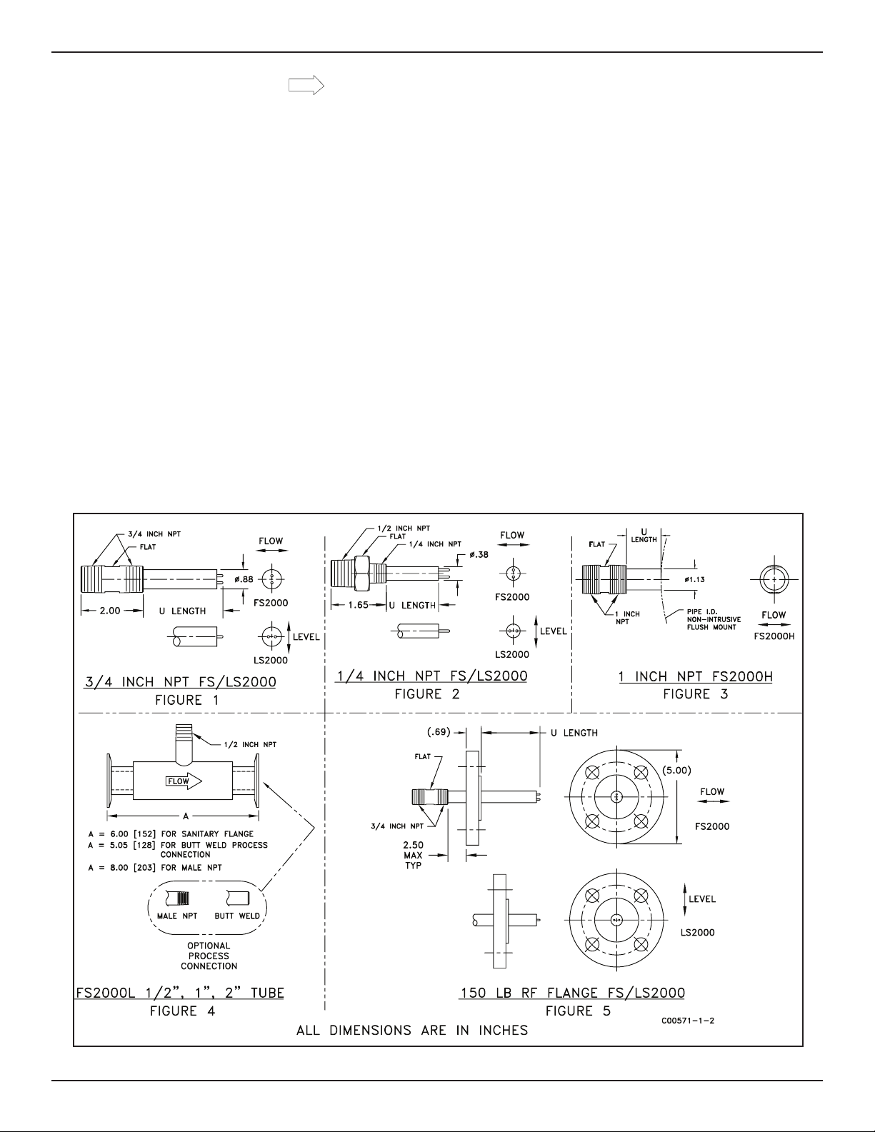
The model LS2000 is an insertion instrument capable of detecting liquid levels or product interfaces in a wide range of processes. The instrument
can be top or side mounted. The process connection choices are male ¼ inch NPT, ¾ inch NPT or 1-1/2 inch, 150 lb. Flange. See the installation
outline drawings on page 3 or 4 for the correct mounting dimensions.
FS2000
The model FS2000 is an insertion instrument capable of detecting flow / no-flow in a wide range of processes. The instrument can be top or side
mounted. The process connection choices are male ¼ inch NPT, ¾ inch NPT or 1-1/2 inch, 150 lb. flange. See the installation outline drawings on
page 3 or 4 for the correct mounting dimensions.
FS2000H
The model FS2000H is an insertion instrument capable of detecting flow/no-flow in a wide range of processes. This probe offers our highest range
for flow detection. This probe is not required to protrude into the process flow, but can be inserted even with the pipe inside diameter and still offer
extended flow ranges. The process connection is a 1” NPT male thread. See the installation outline drawings on pages 3 and 4 for the correct mounting dimensions.
FS2000L
The model FS2000L is a non-intrusive, in-line instrument capable of monitoring the flow rate of a wide range of gas or liquid processes. The instrument can be mounted vertically or horizontally. The process connection choices are male NPT, butt weld or sanitary flange. See the installation
outline drawings on page 3 or 4 for the correct mounting dimensions.
This page is subject to proprietary rights statement on last page
Page 2

Fluid Components International LLC NuTec® Series
SPECIFICATIONS
Model FS2000 Insertion Flow Switch (I)
LS2000 Insertion Level Switch (II)
FS2000H Insertion Flow Switch, High Flow Rate (III)
FS2000L In-Line Flow Switch, Non-Intrusive (IV)
Material of
Construction:
Operating
Temperature:
Maximum
Operating
Pressure:
Input Power: 24 Vac or Vdc. 3 watts Max.
Output:
Installation: Top or Side Mount. Axial flow direction permissible.
Service: General Purpose for Gases and Liquids
Agency
Approvals:
304/305 or 316L Stainless Steel (I & II)
316L Stainless Steel (III & IV)
Sensor Element: -40° to +250°F [-40° to +121°C]
Control Circuit: -0° to +140°F [-18° to +60°C]
For Process Connections With:
Male NPT/Compression Fitting: 500 psig [35 bar (g)]
Butt Weld: 500 psig [35 bar (g)]
Flanges (Sanitary): 100 psig [ 7 bar (g)] (IV)
Flanges (ANSI): Per Specification (I, II)
100 to 240 Vac. 5 watts Max.
2-Wire Loop Power (I, II, IV)
22.5 to 33 Vdc .5 watts Max
Signal
Available on 24 Volt and 100 to 240 input power units.
Alarm indicator is a 6 amp relay, 28 Vdc / 240 Vdc resistive.
Secondary alarm indicator is an open collector circuit (250
mA Maximum).
FS2000, FS2000H and LS2000 Only 2
2-Wire Loop Power: Alarm indicator responds to change in
current draw between 14 mA and 18 mA.
FM, CSA, CE Mark, ATEX, Sanitary 3A, ASME BPE (1997) (IV)
FM, CSA, CE Mark, ATEX, Cenelec (I, II)
FM, CSA, CE Mark, CRN, ATEX 1 (III)
NOTES:
1. Special Conditions for Safe Use:
a. Provisions shall be made to prevent the rated voltage being exceeded
by transient disturbances of more than 40%.
b. For applications in explosive atmospheres caused by air/dust mixtures,
cable and conduit entries used shall provide a degree of ingress
protection of at least IP 54 according to EN 60529.
2. For applications in explosive atmospheres caused by air/dust mixtures,
cable and conduit entries used shall Customer must provide a 4-20mA
current loop that will maintain 18 to 29.5 volts at the controller control
cuircuit.
3. Roman Numerals reflect model designation.
3
3
3
3
Accuracy:
Response
Time:
Setpoint
Range:
Repeatability:
Response
Time:
Setpoint
Range:
Repeatability:
Response
Time:
Setpoint
Range:
Tubing Air / Gas Water
½ inch
1 inch
2 inch
Repeatability:
Accuracy:
Response
Time:
Top Mount: ±0.250 inch [±6mm] from element tip
Side Mount: ±0.125 inch [±3mm] from centerline of
Dry to Wet: Less than 2 seconds
Wet to Dry: Less than 5 seconds
Wet to Wet: interface: Less than 10 seconds
Water: 0.1 – 1.5 fps [0.03 – 0.45 mps]
Hydrocarbon: 0.1 – 2.0 fps [0.03 – 0.60 mps]
Air: 0.5 – 100 sfps [0.15 – 30 nmps]
±1% of Setpoint Range
0.5 – 2.5 Seconds
Water: 0.1 – 10 fps [0.03 – 3 mps]
Hydrocarbon: 0.2 – 20 fps [0.06 – 6 mps]
Air: 0.25 – 750 sfps [0.08 – 230 nmps]
±1% of Setpoint Range
0.5 – 7 Seconds
FS2000L Flow Switch (Non-Intrusive)
Water: 0.1 – 10 fps [0.03 – 3 mps]
Air: 0.5 – 300 sfps [0.15 – 91.4 nmps]
±1% of Alarm Setpoint
±3% of Alarm Setpoint ±0.25% of Setpoint Range
Adjustable from 0.5 – 2.5 Seconds
LS2000 Level Switch
element tip
FS2000 Flow Switch
FS2000H Flow Switch
1.02 – 13.4 scfm 0.03 – 3.4 gpm
[0.000 – 0.38 scmm] [0.11 – 12.9 lpm]
0.12 – 74 scfm 0.18 – 18.5 gpm
[0.0030 – 2.10 scmm] [0.68 – 70 lpm]
0.57 – 342 scfm 0.85 – 85.5 gpm
[0.0160 – 9.70 scmm] [3.22 – 324 lpm]
Section B - Instrument Installation
For the FS2000, FS2000H and the LS2000, there is an orientation mark etched onto the sensor element. It is located on a flattened area of
the sensor element body close to the housing.
For the LS2000, the orientation mark can be perpendicular or parallel to the liquid level. The sensor element can be installed top mount 90º to the
liquid surface.
For the FS2000 and the FS2000H, the orientation mark must be parallel to flow, (± 3º). For liquid vertical flows, FCI recommends that the sensor
element be installed where the flow is going in the up direction.
This page is subject to the proprietary rights statement on the last page 2 Doc. No. 06EN003348 Rev. D
REF
Page 3
NuTec® Series Fluid Components International LLC
FLOW
For the FS2000L, there is a flow arrow mark etched onto the sensor element. It is located on the sensor element body close to the housing.
The sensor element can be at any angle as long as the flow direction follows the flow arrow. Liquid applications where the flow element is positioned other than horizontally, FCI recommends that the flow go in the up direction.
For all models, the position of the sensor element in reference to the media is paramount. With this in mind, the position of the control circuit
enclosure also needs to be considered. After the sensor element is installed, the enclosure cover must be accessible for wiring and servicing. It is
preferred that the conduit port is positioned in a downward direction to reduce the possibility of moisture collecting in the enclosure. The enclosure
may be repositioned by up to ½ turn to facilitate conduit installation.
CAUTION:
To minimize the possibility of damage, leave the protective covers over the sensing area until the time of installation.
Take extra precaution with the sensing elements and surface when installing.
For NPT process connections, apply the appropriate sealant compatible with the process media to the male threads. Tighten until the orientation
mark is positioned correctly. Check for leaks.
For flange connections, refer to the installation outline diagrams. The bolt pattern on the process connection flange must be positioned in a way
that the orientation mark on the sensor element ends up in the correct position as mentioned above. Use gasket material compatible to the process
media. Check for leaks.
For sanitary flange connections, use o-rings compatible with the media. Position the o-ring(s) and join the sanitary flanges. Install the flange
clamp(s) snug to permit rotation of the sensor element. Rotate the sensor element until the orientation mark is correctly positioned. Tighten the
clamps and check for leaks.
For butt weld connections, make sure all parts are cleaned. Mount the instrument to check fit. Make sure the flow arrow is in the same direction
of flow. Align the inside diameter (I.D.) of the instrument to the I.D. of the your piping. Tack weld in place. A qualified welder should perform welding
per ASME Section IX, Boiler Code. For best results, 100% penetration with the weld size of 1 ½ times the wall thickness is desired. Check for leaks.
Sensor Element Diagrams
Doc. No. 06EN003348 Rev. D 3
This page is subject to the proprietary rights statement on the last page
Page 4

Fluid Components International LLC NuTec® Series
Control Circuit Enclosure Diagrams
Section C - Instrument Wiring
There are three basic wiring configurations with the main difference being the way the instrument is powered. Only qualified personnel are to wire or
test this instrument. The operator assumes all responsibilities for safe practices while wiring or troubleshooting. One of the following wiring instruction and diagrams illustrate the requirements for power input, alarm outputs and safety instructions for the unit being installed.
ALERT:
The Instrument contains electrostatic discharge (ESD) sensitive devices. Use standard ESD precautions when handling
the instrument.
Recommended Minimum Wire Gauge
The following wire gauge chart specifies the correct wire for the distance to the power source or loads. Note that the open collector option is limited
to 50 ft. It is also recommended that the open collector cable is shielded and that it is not run in the same conduit with the power source or the relay
load.
Maximum Distance for Wire Gauge
Connection
Input Power 100 – 240Vac 22 20 18 16 14 12
Input Power 24(AC or DC) 24 24 22 22 20 18
Loop Power 24 24 22 22 20 18
Relay Output 18 16 14 12 10 x
Open Collector Output 24 22 x x x x
10 ft.
(3M)
50 ft.
(15M)
100 ft.
(30M)
250 ft.
(76M)
500 ft.
(152M)
1000 ft.
(305M)
Grounding
The switch must be properly ground for safety and operational reasons.
100 –240 Vac input power units: A minimum gauge of 14AWG is required on the earth ground terminal. This connection should have a resistance to earth ground less than 1 ohm. Do not connect the earth ground to DC ground (terminals marked “GND” or “COM” or “-”).
24 volt and Two wire (loop powered) units: The earth ground wire will be attached to the inside of the enclosure on a grounding screw along with the
ground wire from the control circuit. Use the recommended wire gauge specified for the input power and distance listed in the chart above. Do not
connect the earth ground to DC ground (terminals marked “GND”, “COM” or “-”).
This page is subject to the proprietary rights statement on the last page 4 Doc. No. 06EN003348 Rev. D
Page 5

NuTec® Series Fluid Components International LLC
Input Power, 100-240 Vac
1. FCI recommends installing an input power disconnect and a fuse near the instrument to interrupt power during installation, maintenance,
calibration, alarm selection and troubleshooting procedures. Conduit should also be installed according to the local electrical codes
or hazardous location requirements. If the wires are to be pulled through the enclosure it is recommended that the control circuits be
removed from the housing.
2. Ensure the power is off to the instrument before wiring the instrument.
3. With the enclosure cover removed, locate the 4-40 hold down screw next to the serial number block on the top control circuit (see Figure
12). Loosen the screw to release the edge of the top control circuit and flip up the top circuit to expose the bottom circuit.
Note: The 4-40 screw is captive on the control circuit.
4. If the control circuit requires removal, disconnect the sensor element wires from TB3 using a 3/32” flat head screwdriver. Remove the
two Phillips screws on the bottom control circuit and pull the control circuit assembly out of the enclosure enough to expose the ground
wire. Disconnect the ground wire and remove the control circuit assembly from the enclosure. After pulling wire to the enclosure, reassemble the control circuit assembly back into the enclosure before wiring the power and output. Make sure the green ground wire is
reconnected to the enclosure.
5. Attach the ac power leads to TB4 as indicated on the control circuit. Make sure that an earth ground wire is attached to the earth ground
terminal. See figure 9.
6. Attach the relay load wires to TB5. The relay contact conditions are shown in the alarm state (de-energized). The relay’s maximum rating
is 6 amps 28Vdc-100/240Vac, resistive loads. The minimum current and voltage rating 20mA, 10 volts. If the load is less than the minimum values use the open collector terminal on TB1, top control circuit.
7. After making the connections to TB4 and TB5 (TB1), secure all the wires to the tie down bracket with a cable tie wrap. See figure 9. This
is required by safety agencies to act as a strain relief and to prevent fly off of a wire with high voltage potential.
8. After making all the wire connections, flip down the top control circuit and secure it with the 4-40 captive screw.
9. Refer to the next section for functional verification and adjustments.
Input Power, 24 Vdc/Vac
1. FCI recommends installing an input power disconnect and a fuse near the instrument to interrupt power during installation, maintenance,
calibration, alarm selection and troubleshooting procedures. Conduit should also be installed according to the local electrical codes or
hazardous location requirements. If the wires are to be pulled through the enclosure it is recommended that the electronics be removed
from the housing.
2. With the enclosure cover removed, locate the 4-40 hold down screw next to the serial number block on the top control circuit (see Figure
12). Loosen the screw to release the edge of the top control circuit and flip up the top control circuit to expose the terminal blocks on the
bottom side.
Note: The 4-40 screw is captive on the control circuit.
3. If the control circuit requires removal, remove the green ground wire going to the ground screw. Disconnect the sensor element wires
from TB3 using a 3/32” flat head screwdriver. Position the control circuit at a 45º angle to the plastic standoffs and snap the control
circuit off the standoffs. Reinstall the control circuit before connecting the power and loads. To reassemble, snap the control circuit on
the plastic standoffs at a 45º angle to the plastic standoffs and reconnect the element wiring.
4. Determine the type of power to be used (24Vac or 24Vdc) and attach the power leads to TB1 as indicated on the control circuit. See
Figure 10. Make sure that an earth ground wire is attached to the earth ground terminal inside the housing.
5. Attach the relay load wires to TB2. The relay contact conditions are shown in the alarm state (de-energized). The relay’s maximum rating
is 6 amps 28Vdc-100/240 Vac, resistive loads. The minimum current and voltage rating 20 mA, 10 volts. If the load is less than these
values use the open collector terminal on TB1 See Figure 10.
6. After making all the wire connections, flip down the top control circuit and secure it with the 4-40 captive screw.
Refer to the next section for the set point and alarm state settings.
Doc. No. 06EN003348 Rev. D 5
This page is subject to the proprietary rights statement on the last page
Page 6

Fluid Components International LLC NuTec® Series
Input Power, Two Wire (Loop Power)
1. FCI recommends installing an input power disconnect and a 1/8 amp, fast blow fuse near the instrument to interrupt power during
installation, maintenance, calibration, alarm selection and troubleshooting procedures. Conduit should also be installed according to the
local electrical codes or hazardous location requirements. If the wires are to be pulled through the enclosure it is recommended that the
electronics be removed from the housing.
2. With the enclosure cover removed, slide the control circuit out half way to expose terminal block P1, Figure 13.
3. If the control circuit requires removal, slide out the control circuit and remove the green ground wire going to the ground screw. Disconnect the sensor element wires from the Ref and Act. Reinstall the control circuit before connecting the power and loads.
4. Connect the loop power leads to P1 as indicated on the control circuit. See Figure 11. Make sure that an earth ground wire is attached to
the earth ground terminal inside the housing. It is very important that the current loop connected to P1 maintains a voltage rang between
18 and 29.5 volts at the control circuit. Figure 11 shows a typical wiring configuration with a current sense device having 250&! impedance. With this load, the power supply can be 22 to 33Vdc. Check the load impedance of the current sense device and the power supply
and see if they are compatible the NuTec instrument.
5. If the open collector switch is needed, make the connections to P1. See example circuit Figure 11.
6. After making all the wire connections, slide the control circuit into the housing until it passes the rim of the housing.
Refer to the next section for the set point and alarm state settings.
POWER
INPUT
5 to 24
Vdc
SUPPLY
ALARM
STATE
5 to 24 Vdc
TIE DOWN
BRACKET FOR
POWER WIRES
INPUT
POWER
RELAY
OUTPUT
RELAY SHOWN
DE-ENERGIZED
24
OR
Vdc
5K
+
-
INPUT RANGE
100-240VAC
50/60Hz
6 AMPS MAX
120/240 VAC
RELAY
OUTPUT
RELAY SHOWN
DE-ENERGIZED
24
Vac
TB4
AC
LINE
AC
NEUT
N/O
COM
N/C
TB5
BOTTOM SIDE
N/O
COM
N/C
TB 2
TB 1
EXAMPLE OF
AN OPEN
COLLECTOR
CIRCUIT
BOTTOM
BOARD
FLUID COMPONENTS INTL
SAN MARCOS CA.
TB6
OF BOARD
24 Vdc
24 Vac
GND
OPEN C
R
RELAY CONTROL
OUTPUT AND
RELAY
+
NuTec
SN
PRE-WIRED
}
ALARM
STATE
5 to 24 Vdc
M
T
EXAMPLE OF
COLLECTOR
Figure 9 100 - 240 Vac Input Power
POWER
SUPPLY
C01066-1-1
5 to 24
Vdc
PRE-WIRED
5K
AN OPEN
CIRCUIT
22 to 33
+
-
24Vdc
POWER
SUPPLY
{
Relay
1.4K
+
-
250 ohm
Vdc
4-20mA Current Loop
(BOTTOM SIDE)
TB 1
18 to 29.5
Vdc
TOP
BOARD
24 Vdc
24 Vac
GND
OPEN C
C01065-1-1
EXAMPLE OF
AN OPEN
COLLECTOR
TB 1
CIRCUIT
CURRENT
+
LOOP
-
+
OPEN
-
COLECTOR
C01067-1-1
Figure 10 24 Vdc/Vac Input Power Figure 11 2 Wire (LoopPower)
This page is subject to the proprietary rights statement on the last page 6 Doc. No. 06EN003348 Rev. D
Page 7

NuTec® Series Fluid Components International LLC
Section D - Power Up, Functional Verication and Adjustment
Before Appling power to the instrument, it is recommended that a third party inspect the installation workmanship. Make sure wires are not pinched
or frayed. Check for matching serial numbers on the sensing element and the control circuit. Verify that the power and alarm circuits are properly
connected. Review the instrument configuration and its application.
On instruments powered by 100 –240Vac or 24Vdc/Vac, the power indicator is a green rectangular LED and the alarm indicator is a red rectangular
LED. On instruments powered with two wires (loop power), power is indicated by either one of the red LEDs at the edge of the control circuit. The
bottom LED (closest to control circuit) is the flow/wet indicator and the top LED is the no-flow/dry indicator.
Apply power and look for the power indicator light. After power is established let the instrument warm up for 5 minutes. Run the process at normal
and then at abnormal conditions. In most cases the instrument will detect a flow or level alarm with the factory settings. If the Instrument does not
respond, responds slowly or the alarm responds opposite to the required indication, proceed to the section pertaining to the type of control circuit
provided. Refer to Figure 12 and 13 to familiarize yourself with the location of the adjustment potentiometers and jumpers.
SET POINT
ADJUSMENT
ALARM STATUS
INDICATOR
(RED)
ALARM LOGIC
JUMPERS
J2 J1 J3 J4
R1
R25
CR1
R26
CR10
TP1 +
TP2 -
K1
C1
Signal Output
CALIBRATION
ADJUSTMENT
(Active when J3 is in)
MODE JUMPERS:
OPERATE(J3) /
CALIBRATE(J4)
POWER
INDICATOR
(GREEN)
TEMP COMP AJUSTMENT
(DO NOT ADJUST)
4-40 Hold
Down Screw
C01068-1-1
Figure 12 Control Board Adjustments for 100-240 Vac and 24 Vdc/Vac Power Input
Adjustment by Observation - Input Power, 100-240Vac 24Vdc/Vac
The following instructions are for both flow and [wet/dry] applications. NOTE: Do not adjust R26 located between the green LED and the edge of the
control circuit.
Detecting Decreasing Flow or [Dry] (Low Flow/[Dry] Alarm, jumper at J2)
Run the process at normal flow [raise the level]. If the alarm status LED is off, turn the set point adjustment potentiometer (pot) R1 clockwise until
LED turns on. With the LED on, slowly turn the pot counterclockwise until the LED just turns off. Adjust the pot one-quarter turn counterclockwise
past the point where LED turns off. Stop the process flow [lower level]. And verify that instrument has switched to the alarm state.
Detecting Increasing Flow or [Wet] (High Flow/[Wet] Alarm, jumper at J1)
Run the process at normal flow [lower the level]. If the alarm status LED is off, turn the set point adjustment potentiometer (pot) R1 clockwise until
LED turns on. With the LED on, slowly turn the pot counterclockwise until the LED just turns off. Adjust the pot one-quarter turn counterclockwise
past the point where LED turns off. Increase the process flow [raise level]. And verify that instrument has switched to the alarm state.
Adjustment by Measurement - Input Power, 100-240Vac 24Vdc/Vac
The following instructions are for both flow and [wet/dry] applications. Verify that the mode jumper is in the operation position (J3). Attach a DVM
to TP1(+) and TP2(-). Establish a normal flow [wet or dry] condition, letting the instrument stabilize. Record the TP1 to TP2 voltage. Go to one of the
following procedures as applicable.
NOTE:
Do not adjust R26 located between the green LED and the edge of the control circuit.
Doc. No. 06EN003348 Rev. D 7
This page is subject to the proprietary rights statement on the last page
Page 8

Fluid Components International LLC NuTec® Series
4
8
12
16
20
CURRENT LOOP (mA)
PROCESS ALARM: 18 mA +/- 0.5mA
PROCESS NORMAL: 14 mA +/- 0.5mA
LOOP STATUS
( mA indications may be reversed. )
HATCHED AREA = INSTRUMENT OR LOOP TROUBLE
C01070-1-1
Detecting Decreasing Flow or [Dry] (Low Flow/[Dry] Alarm, jumper at J2)
Stop the process flow [lower level] allowing the instrument to stabilize. Record the TP1 to TP2 voltage. Average the normal and the abnormal process condition voltages (i.e., if the normal reading is 7 volts and the abnormal reading is 8 volts, the average or set point is 7.5 volts). The calculated
set point must be at least 0.04 volts over the normal condition. Change the mode jumper to the Calibrate (Cal) position, (J4). Adjust the cal pot (R25)
until the DVM equals the calculated set point voltage. If the Red LED is off, turn the set point pot slowly counterclockwise until the LED turns on. If
the LED is on, turn the pot (R1) clockwise until the LED turns off, then slowly turn the pot counterclockwise until the LED just turn on. Set the calibration jumper to the operate position (J3).
Detecting Increasing Flow or [Wet] (High Flow/[Wet] Alarm, jumper at J1)
Start an excessive process flow [raise level] allowing the instrument to stabilize. Record the TP1 to TP2 voltage. Average the normal and the abnormal process condition voltages (i.e., if the normal reading is 7 volts and the abnormal reading is 6 volts, the average or set point is 6.5 volts). The
calculated set point must be at least 0.04 volts below the normal condition. Change the mode jumper to the Calibrate (Cal) position, (J4). Adjust the
cal pot (R25) until the DVM equals the calculated set point voltage. If the Red LED is on, turn the set point pot slowly counterclockwise until the LED
turns off. If the LED is off, turn the pot (R1) clockwise until the LED turns on, then slowly turn the pot counterclockwise until the LED just turn off. Set
the calibration jumper to the operate position (J3).
Adjustment by Observation - Input Power, Two Wire (Loop Power)
The following instructions are for both flow and [wet/dry] applications.
NOTE:
Do not adjust R32A and R35A located in the middle of the control circuit.
Detecting Flow or [Wet (high level alarm)]
Set J1 to the “Wet/Flow” position. With the sensing element at no-flow or [dry], turn the set point potentiometer (pot) to the point where the LEDs
toggle back and forth (clockwise to turn on the top LED, CR3, and counterclockwise to turn on the bottom LED, CR2). Turn the pot one turn clockwise
past the point where the top LED (CR3) turns on. Turn on the flow [raise liquid level] and verify that the instrument switches to the alarm state when
flowing or [wet].
Detecting No-Flow or [Dry (low level alarm)]
Set J1 to the “Dry/No-Flow” position. With the sensing element at flow or [wet], turn the set point potentiometer (pot) to the point where the LEDs
toggle back and forth (clockwise to turn on the top LED, CR3, and counterclockwise to turn on the bottom LED, CR2). Turn the pot one turn counterclockwise past the point where the bottom LED (CR2) turns on. Stop the flow [lower liquid level] and verify that the instrument switches to the alarm
state when not flowing or [dry].
OPEN COLLECTOR
OUTPUT
INPUT LOOP POWER
ALARM JUMPERS
SET POINT
ADJUSTMENT POT
PROCESS STATUS
LEDs
NO-FLOW / DRY (CR3)
C01069-1-1
FLOW / WET (CR2)
P1
OPEN
-
COLLECTOR
+
-
CURRENT
LOOP
+
FLOW
DRY /
J1
FLOW
WET /
SENSOR
STATUS
NO-
SET POINT
ADJUST
Figure 13 Loop Power Control Circuit Figure 14 4-20mA Loop Power Alarm Settings
Section E - Maintenance and Troubleshooting
Maintenance: Typically required for the sensing element. If the process media sticks to the process pipes (or tank) the sensing element should be
cleaned in the same manner and frequency as the process pipe (or tank). Occasionally check for moisture in the control circuit housing and wiring
connections. Check for proper functionality and response time.
Troubleshooting: If the instrument is not operating, go through the installation and adjustment procedures and verify proper installation. If the
instrument fails after some time in service and it has been checked, or if it fails to operate at start up and the installation has been verified, contact
FCI Technical Service. If the instrument is to be returned, obtain a Return Authorization. The form contains a declaration of decontamination cleaning
information that the instrument must comply with before it is shipped to FCI. The telephone number is 1-800-854-1993 or 1-760-744-6950.
This page is subject to the proprietary rights statement on the last page 8 Doc. No. 06EN003348 Rev. D
Page 9
NuTec® Series Fluid Components International LLC
Section F - Approval Information
CE
Information
CE DECLARATION OF CONFORMITY
FS2000/LS2000/FS2000L/FS2000H Series
We, Fluid Components Intl, located at 1755 La Costa Meadows Drive, San Marcos, California 920695187 USA, declare under our sole responsibility that the FS2000/LS2000/FS2000L/FS2000H Series,
Flow and Level Monitoring Switches, to which this declaration relates, are in conformity with the
following standards and Directives.
EMC Directive 89/336/EEC, May 3, 1989 of the European Union
Immunity specification
EN 61000-4-11 /1994 (FS2000L only)
Emissions specification
(Conducted emissions not tested, not applicable for industrial standard)
Pressure Equipment Directive 97/23/EC.
The FS2000, LS2000 and FS2000H Models do not have a pressure bearing housing and are therefore
not considered as pressure equipment by themselves according to article 1, section 2.1 of the Directive.
Model FS2000L is in conformity with the sound engineering practices as defined in the Pressure
Equipment Directive (PED) 97/23/EC article 3, paragraph 3, instruments with a line size greater than 25
mm are limited by the requirements of Annex II, table 6 as define in article 3 section 1.3.
Issued at San Marcos, California USA
23, June 2004
_______________________________
Eric J. Wible, Engineering Manager
: EN 61000-6-2 /1998, EN 61000-4-2,-3,-4,-5 /1995, EN 61000-4-6 /1996
: EN55022 1998 Class A and CISPR 22 1997 Class A.
Eric Wible
2004.09.28
15:22:48 -08'00'
Flow/Liquid Level/Temperature Instrumentation
1755 La Costa Meadows Drive, San Marcos, California 92069 USA 760-744-6950 800-854-1993 760-736-6250
European Office: Persephonestraat 3-01 5047 TTTilburg – The Netherlands – Phone 31-13-5159989 Fax 31-13 -5799036
Doc no. 23EN000008B
Visit FCI on the Worldwide Web: www.fluidcomponents.com
Doc. No. 06EN003348 Rev. D 9
This page is subject to the proprietary rights statement on the last page
Page 10

Fluid Components International LLC NuTec® Series
Safety Instructions for the use of the FS2000L, FS2000 and LS2000 Flow & Level Monitoring
Switches in Hazardous Areas
Approval KEMA 04 ATEX 1135X for Category II 3GD protection EEx nA II T6 T62°C
Category II 3GD protection EEx nC IIC T6 T62°C
Dansk Sikkerhedsforskrier Italiano Normative di sicurezza
Deutsch Sicherheitshinweise Nederlands Veiligheidsinstructies
English Safety instructions Português Normas de segurança
Υπ Υπ_δεί_εις ασφαλείας Español Instrucciones de seguridad
Suomi Turvallisuusohjeet Svenska Säkerhetsanvisningar
Français Consignes de sécurité
DK Dansk- Sikkerhedsforskrifter
Disse sikkerhedsforskrier gælder for Fluid Components, FS2000L, FS2000 and LS2000 Flow & Level Monitoring Switches EFtypeafprøvningsattest-nr. KEMA 04 ATEX 1135X (attestens nummer på typeskiltet) er egnet til at blive benyttet i eksplosiv atmosfære
kategori II 3 GD.
1) Ex-anlæg skal principielt opstilles af specialiseret personale.
2) FS2000L, FS2000 and LS2000 Flow & Level Monitoring Switches skal jordforbindes.
D A Deutsch-Sicherheitshinweise
Diese Sicherheitshinweise gelten für die Fluid Components, FS2000L, FS2000 and LS2000 Flow & Level Monitoring Switches gemäß
der EG-Baumusterprüescheinigung Nr. KEMA 04 ATEX 1135X (Bescheinigungsnummer auf dem Typschild) der Kategorie II 3 GD.
1) Die Errichtung von Ex-Anlagen muss grundsätzlich durch Fachpersonal vorgenommen werden.
2) Der FS2000L, FS2000 and LS2000 Flow & Level Monitoring Switches muß geerdet werden.
GB IRL English- Safety instructions
ese safety instructions are valid for the Fluid Components, FS2000L, FS2000 and LS2000 Flow & Level Monitoring Switches to
the EC type approval certicate no. KEMA 04 ATEX 1135X (certicate number on the type label) for use in potentially explosive
atmospheres in Category II 3 GD.
1) e installation of Ex-instruments must be made by trained personnel.
2) e FS2000L, FS2000 and LS2000 Flow & Level Monitoring Switches must be grounded.
GR Υπ_δεί_εις ασφαλείας
Αυτές οι οδηγίες ασφαλείας ισχύουν για τα Ροόμετρα της Fluid Components τύπου FS2000L, FS2000 and LS2000 Flow & Level
Monitoring Switches που φέρουν Πιστοποιητικό Εγκρίσεως Ευρωπαϊκής Ένωσης, με αριθμό πιστοποίησης KEMA 04 ATEX 1135X (ο
αριθμός πιστοποίησης βρίσκεται πάνω στην ετικέτα τύπου του οργάνου) για χρήση σε εκρηκτικές ατμόσφαιρες της κατηγορίας II 3 GD.
1) Η εγκατάσταση των οργάνων με αντιεκρηκτική προστασία πρέπει να γίνει από εξειδικευμένο προσωπικό.
2) Το όργανο τύπου FS2000L, FS2000 and LS2000 Flow & Level Monitoring Switches πρέπει να είναι γειωμένο.
FIN Suomi - Turvallisuusohjeet
Nämä turvallisuusohjeet koskevat Flud Components, FS2000L, FS2000 and LS2000 Flow & Level Monitoring Switches EYtyyppitarkastustodistuksen nro. KEMA 04 ATEX 1135X mukaisesti (todistuksen numero näkyy tyyppikilvestä) käytettäessä
räjähdysvaarallisissa tiloissa luokassa II 3 GD.
1) Ex-laitteet on aina asennettava ammattihenkilökunnan toimesta.
2) FS2000L, FS2000 and LS2000 Flow & Level Monitoring Switches on maadoitettava.
This page is subject to the proprietary rights statement on the last page 10 Doc. No. 06EN003348 Rev. D
Page 11

NuTec® Series Fluid Components International LLC
F B L Consignes de sécurité
Ces consignes de sécurité sont valables pour le modèle FS2000L, FS2000 and LS2000 Flow & Level Monitoring Switches de la société
Fluid Components (FCI) conforme au certicat d’épreuves de type KEMA 04 ATEX 1135X (numéro du certicat sur l’étiquette signalétique) conçu pour les applications dans lesquelles un matériel de la catégorie II 3 GD est nécessaire.
1) Seul un personnel spécialisé et qualié est autorisé à installer le matériel Ex.
2) Les FS2000L, FS2000 and LS2000 Flow & Level Monitoring Switches doivent être reliés à la terre.
I Italiano - Normative di sicurezza
Queste normative di sicurezza si riferiscono ai Fluid Components, FS2000L, FS2000 and LS2000 Flow & Level Monitoring Switches
secondo il certicato CE di prova di omologazione n° KEMA 04 ATEX 1135X (numero del certicato sulla targhetta d’identicazione)
sono idonei all’impiego in atmosfere esplosive applicazioni che richiedono apparecchiature elettriche della Categoria II 3 GD.
1) L’installazione di sistemi Ex deve essere eseguita esclusivamente da personale specializzato.
2) I FS2000L, FS2000 and LS2000 Flow & Level Monitoring Switches devono essere collegati a terra.
NL B Nederlands - Veiligheidsinstructies
Deze veiligheidsinstructies gelden voor de Fluid Components, FS2000L, FS2000 and LS2000 Flow & Level Monitoring Switches
overeenkomstig de EG-typeverklaring nr. KEMA 04 ATEX 1135X (nummer van de verklaring op het typeplaatje) voor gebruik in een
explosieve atmosfeer volgens Categorie II 3 GD
1) Installatie van Ex-instrumenten dient altijd te geschieden door geschoold personeel.
2) De FS2000L, FS2000 and LS2000 Flow & Level Monitoring Switches moet geaard worden.
P Português - Normas de segurança
Estas normas de segurança são válidas para os Fluid Components, FS2000L, FS2000 and LS2000 Flow & Level Monitoring Switches
conforme o certicado de teste de modelo N.º KEMA 04 ATEX 1135X (número do certicado na plaqueta com os dados do equipamento) são apropriados para utilização em atmosferas explosivas categoria II 3GD
1) A instalação de equipamentos em zonas sujeitas a explosão deve, por princípio, ser executada por técnicos qualicados.
2) Os FS2000L, FS2000 and LS2000 Flow & Level Monitoring Switches precisam ser ligados à terra.
E Español - Instrucciones de seguridad
Estas indicaciones de seguridad son de aplicación para el modelo FS2000L, FS2000 and LS2000 Flow & Level Monitoring Switches de
Fluid Components, según la certicación CE de modelo Nº KEMA 04 ATEX 1135X para aplicaciones en atmósferas potencialmente
explosivas según la categoría II 3GD(el número de certicación se indica sobre la placa informativa del equipo).
1) La instalación de equipos Ex tiene que ser realizada por personal especializado.
2) Los FS2000L, FS2000 and LS2000 Flow & Level Monitoring Switches tienen que ser conectados a tierra.
S Svenska - Säkerhetsanvisningar
Säkerhetsanvisningarna gäller för Fluid Components, Flödesmätare typ FS2000L, FS2000 and LS2000 Flow & Level Monitoring
Switches enligt EG-typkontrollintyg nr KEMA 04 ATEX 1135X (intygsnumret åternns på typskylten) är lämpad för användning i
explosiv gasblandning i kategori II 3 GD.
1) Installation av Ex- klassade instrument måste alltid utföras av fackpersonal.
2) FS2000L, FS2000 and LS2000 Flow & Level Monitoring Switches måste jordas.
Doc. No. 06EN003348 Rev. D 11
This page is subject to the proprietary rights statement on the last page
Page 12

NuTec® Series
FCI’s Complete Customer Commitment. Worldwide
ISO 9001 and AS9100 Certified
Visit FCI on the Worldwide Web: www.fluidcomponents.com
FCI World Headquarters
1755 La Costa Meadows Drive | San Marcos, California 92078 USA | Phone: 760-744-6950 Toll Free (US): 800-854-1993 Fax: 760-736-6250
FCI Europe
Persephonestraat 3-01 | 5047 TT Tilburg, The Netherlands | Phone: 31-13-5159989 Fax: 31-13-5799036
FCI Measurement and Control Technology (Beijing) Co., LTD | www.fluidcomponents.cn
Room 107, Xianfeng Building II, No.7 Kaituo Road, Shangdi IT Industry Base, Haidian District | Beijing 100085, P. R. China
Phone: 86-10-82782381 Fax: 86-10-58851152
Notice of Proprietary Rights
This document contains confidential technical data, including trade secrets and proprietary information which is the property of Fluid
Components International LLC (FCI). Disclosure of this data to you is expressly conditioned upon your assent that its use is limited to use within your
company only (and does not include manufacture or processing uses). Any other use is strictly prohibited without the prior written consent of FCI.
© Copyright 2012 by Fluid Components International LLC. All rights reserved.
Manufactured in accordance with one or more of the following patents: 6,608,254; 6,304,243; 6,628,202; ZL00815586.0.
FCI is a registered trademark of Fluid Components International LLC. Information subject to change without notice.
Fluid Components International LLC 06EN003348 Rev. D
 Loading...