

Page 1

Page 2

FS10 Series
This document contains confidential technical data, including trade secrets and proprietary information which is the property of Fluid Components International LLC (FCI).
Disclosure of this data to you is expressly conditioned upon your assent that its use is limited to use within your company only (and does not include manufacture or
processing uses). Any other use is strictly prohibited without the prior written consent of FCI.
© Copyright 2011 by Fluid Components International LLC. All rights reserved. FCI is a registered trademark of Fluid Components International LLC. Information subject to change without notice.
Notice of Proprietary Rights
Fluid Components International LLC
Page 3

FS10 Series 06EN003394 Rev. D
Table of Contents
Technical Specification ................................................................................................................................................................................3
1 INSTRUMENT DESCRIPTION AND IDENTIFICATION .........................................................................................................................4
2 INSTRUMENT INSTALLATION ................................................................................................................................................................4
Special Conditions for Safe Use: .....................................................................................................................................................................................4
Mounting Orientation .......................................................................................................................................................................................................5
3 INSTRUMENT WIRING .............................................................................................................................................................................6
Recommended Minimum Wire Gauge ............................................................................................................................................................................6
Grounding .........................................................................................................................................................................................................................6
Input Power, 24 Vdc ..........................................................................................................................................................................................................6
4 POWER UP, FUNCTIONAL VERIFICTAION AND ADJUSTMENT ........................................................................................................6
Switching Inductive Loads................................................................................................................................................................................................9
5 SET-UP AND OPERATION ......................................................................................................................................................................13
FS10 Function Overview .................................................................................................................................................................................................13
FS10 Field Quick Setup Procedure..................................................................................................................................................................................14
FS10 Button Controls ......................................................................................................................................................................................................15
Normal set-up and operation using the button interface ..............................................................................................................................................16
Bank Selection of Stored Parameters (Function 4) .....................................................................................................................................................16
Flow Switch Operation ...................................................................................................................................................................................................17
Minimum Flow Setting (Function 6) ............................................................................................................................................................................17
Maximum Flow Setting (Function 7) ...........................................................................................................................................................................17
Static/Dynamic Mode Option (Function 5) ..................................................................................................................................................................17
Trip Point Adjust (Function 1 or 2) ...............................................................................................................................................................................17
There are two ways to set the trip point using the buttons. .....................................................................................................................................17
Additional Switch Settings.............................................................................................................................................................................................17
Failsafe Position (Function 3) ......................................................................................................................................................................................17
Hysteresis (Function 8 and 9) ......................................................................................................................................................................................17
Time Delay (Function 10 or 11) ....................................................................................................................................................................................18
Alarm Simulation (Function 12) ...................................................................................................................................................................................18
Keypad Lockout (Function 13)......................................................................................................................................................................................18
Filter Setting (Function 14) ..........................................................................................................................................................................................18
Save to Bank (Function 15) ..........................................................................................................................................................................................18
Output and Display Parameters......................................................................................................................................................................................19
PC Interface and Command Line Interface Configurations ...........................................................................................................................................22
FS10 Communication Options .....................................................................................................................................................................................22
Password Protection....................................................................................................................................................................................................22
Flow Rate Indication on PC Interface ..........................................................................................................................................................................22
Power Supply Interface Kit..........................................................................................................................................................................................22
PC Interface Software .................................................................................................................................................................................................23
PC Interface Software .................................................................................................................................................................................................25
Fluid Components International LLC 1
Page 4

06EN003394 Rev. D FS10 Series
FS10 Serial Interface ......................................................................................................................................................................................................26
Command Line Interface Commands..............................................................................................................................................................................28
6 MAINTENANCE AND TROUBLESHOOTING .......................................................................................................................................32
Maintenance ...............................................................................................................................................................................................................32
Troubleshooting ...........................................................................................................................................................................................................32
APPENDIX A APPROVALS ........................................................................................................................................................................34
APPENDIX B AUXILIARY DRAWINGS ....................................................................................................................................................38
PC Interface Kits .............................................................................................................................................................................................................41
022083-02 Power Supply/Interface Box Kit ...................................................................................................................................................................42
022083-01 Power Supply/Interface Box.........................................................................................................................................................................42
PC Interface Components ...............................................................................................................................................................................................43
Board Connectors - OEM ................................................................................................................................................................................................44
DB9 Connection Schematic ............................................................................................................................................................................................45
APPENDIX C CUSTOMER SERVICE ......................................................................................................................................................... 46
Customer Service/ Technical Support .........................................................................................................................................................................46
Warranty Repairs or Returns .......................................................................................................................................................................................46
Non-Warranty Repairs or Returns ...............................................................................................................................................................................46
Extended Warranty ......................................................................................................................................................................................................47
Return to Stock Equipment..........................................................................................................................................................................................47
Field Service Procedures .............................................................................................................................................................................................47
Field Service Rates ......................................................................................................................................................................................................47
Return Authorization Request ...................................................................................................................................................................................48
2 Fluid Components International LLC
Page 5

FS10 Series
Technical Specification
Instrument
Media Compatibility
All gases and liquids compatible with 316L stainless steel and
hastelloy C22.
Process Connection
1/4” NPT; compatible with 1/4”, 3/8” and 1/2” tube tee,
1/4” tube tee with 1/8” injection tube adapters and SP76 adapter
(FCI part number 019897-01)
Flow Sensitivity/Range:
Air / Gas Liquids
CC / Min SCFH CC / Min GPH
Min Max Min Max Min Max Min Max
1/8” tube adapter with
0.0625” ID injection tube
1/8” tube adapter with
0.0940” ID injection tube
1/4” tube tee 50 20,000 0.10 40 4.00 100.00 0.07 1.70
SP76 adapter 50 20,000 0.10 40 4.00 100.00 0.07 1.70
3/8” tube tee
1/2” tube tee
10 2,000 0.02 5 0.70 18.00 0.01 0.30
25 5,000 0.05 10 1.50 40.00 0.03 0.60
180
50,000 0.40 100
375
100,000 0.80 200
14.00
350.00 0.20 5.50
30.00
750.00 0.50 12.00
Repeatability:
± 0.5% of reading
Temperature Coefficient
For temperatures > ± 30 °F [± 16 °C]
Gas: Maximum ± 0.025% of reading/°F up to 500 °F
[± 0.05% of reading/°C up to 260 °C]
Liquid: Maximum ± 0.2% of reading/°F up to 250 °F
[± 0.367% of reading/°C up to 121 °C]
Turndown Ratio: 5:1 to 100:1
Agency Approvals
FM, FMc: Nonincendive, Class I Division 2 Groups A, B, C, D;
Class II, Division 2 Groups E, F, G; Class III,
T4@Ta=71°C Type 4X
ATEX, IEC: Nonincendive for gas and dust, Zone 2
II 3 G Ex nA IIC T4 Gc
II 3 D Ex tc IIIC T 81°C Dc
IP64
CE Mark
Transmitter/Electronics
Enclosure
NEMA 4X [IP64], anodized aluminum
Operating Temperature
-40 °F to 160 °F [-40 °C to 71 °C]
Output Signals
Standard:
(1) Relay (SPDT, 1A @ 24 Vdc); [1A @ 24 Vdc / 120 Vac, FM and
FMc only] or (1) Open Collector N-Channel MOSFET (100 mA);
(1) 4-20 mA * (500 Ω max. load). User scalable, general purpose,
un-calibrated output proportional to flow rate for trend monitoring.
(1) RS232C Serial I/O
(For linearized, calibrated analog outputs see FCI thermal mass
flow meter products)
* Fault indication per NAMUR NE43 guidelines, user selectable
high (> 21.0 mA) or low (< 3.6 mA)
Other Digital Comms: Contact FCI
Display
10 LED array, red; sequential lighting proportional to flow trend and
flashes at setpoint
User Interface
Two top-mounted push buttons to program switch/trip point, zero and
span setting, relay hysteresis and time delay; button operation may
be user disabled to prevent unwanted changes; all set-up functions
also programmable via RS232C port
Input Power
24 Vdc (21.5 Vdc to 30 Vdc); maximum 2.5 watts
Remote Configuration
Transmitter/electronics may be remote-mounted from flow element
using interconnecting cable; remote flow element available with
potted cable in 6’, 15’ or 30’ [2m, 5m or 10m] length and M12 connection plug at electronics; optional extended temperature service to
500 °F [260 °C] with selection of PTFE jacketed cable.
Flow Element
Materials of Construction (Wetted parts) 316L stainless steel with
Hastelloy C-22 thermowells; optional, all Hastelloy-C22 probe
assembly
Operating Temperature
Standard: -40 °F to 250 °F [-40 °C to 121 °C]
Optional: -40 °F to 500 °F [-40 °C to 260 °C]; remote configuration
only
Operating Pressure
Tube tee fitting: 500 psig [34 bar (g)]
SP76 adapter: Per SP76 manifold specifications up to 500 psig
[34 bar (g)] maximum
Fluid Components International LLC 3
Page 6

FS10 Series
1 INSTRUMENT DESCRIPTION AND IDENTIFICATION
The FS10A is a universal flow monitor and switch specifically designed for gas and liquid process analyzer sampling systems. The FS10A is a fast
responding, highly repeatable sensor which installs easily into a standard tube tee fitting or SP76 (NeSSI) modular manifold.
2 INSTRUMENT INSTALLATION
The FS10 is marked with a flow direction arrow or “A” etched onto the sensor element. It is located on the flattened area of the sensor body
close to the housing or on the assembled tee. In 1/4 and 3/8 inch tube tees, the “A” should be mounted upstream of the flow to maximize sensitivity
at low flow rates (flow into the “A”). Larger line sizes should follow the flow arrow direction. Refer to Table 1 for optimum results. Where the flow
tube is not included with the sensor assembly, the orientation mark must be parallel to flow (±3°). For liquid vertical flows in particular, FCI
recommends the sensor element be installed where flow is in the up direction. In vertical low flow gas applications, flow in the
down direction is recommended.
As a level device, the orientation mark can be perpendicular or parallel to the liquid level. The sensor element may be installed top mount 90° to
the liquid surface. The sensor element can be at any angle as long as the flow direction follows the flow arrow. Liquid applications where the flow
element is positioned other than horizontally, FCI recommends the flow go in the up direction.
CAUTION: To minimize the possibility of damage, leave the protective covers over the sensing area until the time of installation. Take
extra precaution with the sensing elements and surface when installing.
For NPT process connections, apply the appropriate sealant compatible with the process media to the male threads. Tighten until the orientation
mark is positioned correctly. Check for leaks.
Special Conditions for Safe Use:
a. Provisions shall be made to prevent the rated voltage being exceeded by transient disturbances of more than 40%.
b. For applications in explosive atmospheres caused by air/dust mixtures, cable and conduit entries used shall provide a degree of ingress
protection of at least IP 54 according to EN 60529.
c. When the temperature under rated conditions exceeds 158 °F [70 °C] at the cable or conduit entry point, or 176 °F [80 °C] at the branching
point of the conductors, the temperature specification of the selected cable shall be in compliance with the actual
measured temperature.
d. Cable gland assemblies are factory tightened – do not adjust; M12 connectors assembled finger-tight. Mencom MDC-8MR-PG9 or equal
M12 connector is used on FS10A.
4 Fluid Components International LLC
Page 7

FS10 Series
Mounting Orientation
Flow Direction
“A” (Active) mark
Upstream
Sensors parallel
Left to Right Flow Example in 1/4 and 3/8 inch tube tees
For optimum sensitivity in low flow applications, probes should
be installed with the “A” (Active) sensor positioned upstream.
Horizontal lines: gas or liquid.
Vertical lines: gas - flow must be down
liquid - flow must be up
Flow Direction Arrow
Sensors perpendicular
Right to Left Flow Example in 1/2 inch or greater tube or
pipe tee
Probes mounted into 1/2 inch or greater tees are installed with
the sensors positioned perpendicular to the flow path in the
tee. “A” (Active) should be facing up in side mount horizontal
configurations. These sensors may also be marked with a flow
direction arrow.
Diagram 1
Fluid Components International LLC 5
Page 8

FS10 Series
3 INSTRUMENT WIRING
Only qualified personnel are to wire or test this instrument. The operator assumes all responsibilities for safe practices while wiring or troubleshooting. One of the following wiring instruction and diagrams illustrate the requirements for power input, alarm and analog outputs and safety instructions for the unit being installed.
ALERT: The Instrument contains electrostatic discharge (ESD) sensitive devices. Use standard ESD precautions when handling the
instrument.
Recommended Minimum Wire Gauge
The following wire gauge chart specifies the correct wire for the distance to the power source or loads. Note that the open collector option is limited
to 50 ft. It is also recommended that the open collector cable is shielded and that it is not run in the same conduit with the power source or the relay
load.
I/O Wiring Gauge vs. Distance
Maximum Diameter (guage)
Connection
Input Power (24 Vdc nominal) 24 24 22 22 20 18
Relay Output (1 amp contacts) 18 16 14 12 10 X
10 ′ 50 ′ 100 ′ 250 ′ 500 ′ 1000 ′
(3 m) (15 m) (30 m) (76 m) (152 m) (305 m)
Open Collector Output 24 22 X X X X
4-20 mA Output 24 24 22 22 20 18
Table 1
Grounding
The switch must be properly grounded for safety and operational reasons.
The circuit board is tied to the enclosure case internally and both are tied to the probe assembly. If the installation pipe or vessel is not properly
grounded, connection to earth ground may be connected at the output connector, i.e. M12 or cable pigtail. Use the recommended wire gauge specified for the input power and distance listed in the chart above. Do not connect the earth ground to DC ground (terminals marked “GND”,
“COM” or “-”).
Input Power, 24 Vdc
FCI recommends installing an input power disconnect and a fuse near the instrument to interrupt power during installation, maintenance, calibration, alarm selection and troubleshooting procedures. Conduit should also be installed according to the local electrical codes or hazardous location
requirements.
Attach the power leads according to the Input/Output connection schematic on the following page. If the unit has an M12 interface, verify that the
mating connector pin numbers match the designations of the wiring diagram. If the unit is supplied with a cable pigtail, the flying leads should be
connected via an approved terminal block or connector in an electrically safe and approved conduit box.
Attach the wires to the relay and other functions as needed. The relay contact conditions are shown in the alarm state (de-energized). The relay’s maximum rating is 1 amp 24Vdc, 120 Vac (FM only), 24 Vdc (ATEX), resistive loads.
Refer to the next section for the set point and alarm state settings.
4 POWER UP, FUNCTIONAL VERIFICTAION AND ADJUSTMENT
Before Applying power to the instrument, it is recommended that a third party inspect the installation workmanship. Make sure wires are not pinched
or frayed. Check for matching serial numbers on the sensing element and the control circuit. Verify that the power and alarm circuits are properly
connected. Review the instrument configuration and its application.
Units supplied with LED’s will have at least one LED on or slowly blinking to indicate power on. Apply power and look for the power indicator light.
After power is established let the instrument warm up for 5 minutes. Refer to set-up on following pages. The switch must be properly grounded for
safety and operational reasons.
6 Fluid Components International LLC
Page 9

FS10 Series
Fluid Components International LLC 7
Page 10

FS10 Series
8 Fluid Components International LLC
Page 11

FS10 Series
(OEM)
Switching Inductive Loads
If the FS10A relay contacts are to be used to energize or de-energize an external relay, diode suppression must be used across the external relay coil.
Use the guidelines in the following example to select the proper diode.
A Tyco Electronics relay K10P-11D15-24 is used as a slave relay. The DC coil voltage is specified at 24 Vdc and the specification indicates a coil
resistance of 650Ω. The DC coil current is calculated by dividing the Rated coil power by the Rated Voltage Vdc or dividing the Rated Voltage Vdc by
the Coil resistance. In this case the current through the coil will be around 37mA (24/650). Refer to the K10P-11D15-24 data sheet.
It is recommended the Diode Reverse Voltage (Vr) rating be twice or greater the voltage across the relay and the diode forward current (IF) rating be
greater than the relay current. Diodes 1N914 or 1N4148 meet these limits for this case.
Fluid Components International LLC 9
Page 12

FS10 Series
10 Fluid Components International LLC
Page 13

FS10 Series
FS10 Flow Element Options
Fluid Components International LLC 11
Page 14

FS10 Series
FS10 Remote Enclosure and Connector Options
12 Fluid Components International LLC
Page 15

FS10 Series
5 SET-UP AND OPERATION
FS10 Function Overview
The FS10 flow monitor may come configured for use as a flow or temperature meter. The output of the switch configuration is a SPDT relay contact or
binary collector to ground [N-channel MOSFET] output (sync). A 4-20 mA output signal is also active as a signal reference. In the transmitter configuration, either the flow or temperature functions may be assigned to the 4-20 mA output. The table below shows the possible output configurations,
including the status of the LED bar display.
Output Configuration [Field Selectable with PC Interface Kit]
Configuration 4-20 ma Output Relay on/off Output LEDs
1
(default)
Corresponds to Flow
measurement
Controls Relay switch on/off
from Flow
Reflects Flow. Flashing LED
indicates Relay Limit.
4 Corresponds to Temp
measurement
5 Corresponds to Temp
measurement
Controls Relay switch on/off
from Flow
Controls Relay switch on/off
from Flow
Reflects Temperature. No
Relay Limit indication.
Reflects Flow. Flashing LED
indicates Relay Limit.
Table 2
• Flow measurement will be mapped using CUST_FLOW_MIN and CUST_FLOW_MAX in the 4-20 mA output configuration.
• Temperature measurement will be mapped using CUST_TEMP_MIN and CUST_TEMP_MAX in the output configuration and reflected
in the 4-20 mA output when configuration 4 or 5 is selected. The default temperature range mapped to the 4-20 mA
output is 0 °F to 250 °F [-17.8 °C to 121 °C]. Rescaling temperature output may be performed with the PC interface program.
The output configuration setting is normally factory set but may be changed in the field if required. Caution should be used when making any
configuration changes, as the monitor may not have been properly calibrated to accommodate the new setting. Only the RS232 interface may
be used to make a change in output configuration.
Fluid Components International LLC 13
Page 16

FS10 Series
FS10 Field Quick Setup Procedure
Quick Setup Mode *
This feature permits field setting the critical zero and span parameters of the FS10A with a single push of the button and throttling the process flow
over the desired range to capture the low and high ends. All defaults applicable to a low flow indication/alarm application apply along with a
trip-point default setting at 30% of span.
To activate the Quick Setup Mode (QSM), simply press and hold for at least 10 seconds:
“ – “ button, for process fluids that are gases or very low flow liquid hydrocarbons
“ + “ button, for process fluids that are liquids or high velocity gases (+50% sensor excitation).
The first three and last three LEDs will alternately flash to acknowledge entry into the Quick Setup Mode. The FS10A is now cued to remember the
lowest and highest flow signal it sees while in this mode. Pressing either button momentarily exits into the normal operating mode and saves the
detected limits as the zero and span. LED’s 1 and 10 and corresponding trip point LED will alternately flash (3 sec), indicating zero and span have
been properly set.
A minimum span setting of 0.05% is required to save new parameters. If minimum span is not reached during QSM, the first two, middle two and
last two LEDs will flash; indicating an error (3 sec) and resume last operation without saving new parameters.
Recommendations
Gas applications
The high flow limit or span setting is normally the most difficult to stabilize in a gas application, therefore simulating the desired high flow rate at
normal process conditions and allowing it to stabilize before entering into the QSM is recommended. Using in-line valves or other throttling means,
establish the desired full scale flow rate and allow system to stabilize. Now enter into the QSM (FS10 immediately captures this high flow signal)
and then slowly throttle the flow down until the zero flow setting is reached (i.e. valve closed, no flow). Allow to stabilize, then momentarily press
either button to save parameters and return to normal operating mode with the new scaled operating range established.
Liquid applications
To optimize the performance of the FS10A in liquids, it is critical to establish a stable zero setting under a packed line (full) condition. It is
recommended the FS10A be operating and allowed to come to equilibrium with a downstream valve closed and the line completely filled with the
process fluid and no flow. At this point, enter into the QSM (FS10 immediately captures this low flow signal), and then slowly open the downstream
valve to allow flow up to the maximum span desired. Momentarily press either button to save parameters and return to normal operating mode with
the new scaled operating range established.
In some cases the high liquid flow signal will saturate before reaching the high flow that is simulated, but the FS10A will save the highest value it is
capable of sensing in that application and use it as the high end limit.
Trip point
By factory default, the trip-point is set to 30% of the established span when using the Quick Setup Mode. This may be changed in the field using
the standard button commands (refer to Functions 1 and 2 under Normal set-up and operation using the button interface in the operating manual).
Alternatively, the QSM factory trip-point default of 30% of span may be changed in the field using the PC interface program before entering into the
QSM. Selecting the factory setup option at order will also permit designating an alternative customer desired default value at the factory. Note, this
value is always a % of the established span and alters any previous trip point that may have been attained on a previous setup.
Note, the 4-20mA output and relay trip will continue to operate at the previously set range while in the Quick Setup Mode
Summary
1. Activate QSM: Press “-“ button (gas) or “+” button (liquid) minimum 10 seconds (LEDs will acknowledge entry into QSM).
2. Throttle flow valve to simulate zero and full scale flow.
3. Press either button momentarily to save parameter values and exit into normal operating mode.
* FS10A with Firmware version 4.0 or greater
14 Fluid Components International LLC
Page 17

FS10 Series
FS10 Button Controls
It is recommended the unit be powered-up for 10-15 minutes before making changes to any of the flow settings.
General Control Description
The FS10 control “functions” can be accessed through the two buttons by:
1. Entering “function selection”
2. Selecting the desired function to adjust
3. Adjusting the function control
4. Exiting to normal operation
1. To Enter “Function Selection” mode:
a. Press and hold both buttons down for 3 seconds
b. When “function selection” is entered, all the LEDs will flash “on”, then
c. The first function (LED # 1) will be illuminated
2. “Function Selection” mode:
Once the unit is in “function selection” mode, the buttons take on new controls:
• The “-“ and “+” buttons will step (increment down or up respectively) through the different functions. The current function number will
be indicated on the LED blinking at the slow rate.
• Holding either the “+” or “-“ for 3 seconds will “select” the current function to be adjusted.
3. When a Function has been selected for adjustment:
After selecting the desired function by pushing and holding either the “-” or “+” button for 3 seconds the LEDs will flash at a faster rate. The
pattern of the LEDs will either reflect the current value of the parameter being adjusted, or the “ready to capture” pattern for parameters to be
captured (see specific function descriptions for details).
The buttons will either increment or decrement the function parameter, or capture a value for the corresponding parameter.
4. To exit out of the current function, push and hold both buttons down for 3 seconds. The LEDs will indicate that you are once again in “function
election” mode, and the current mode will have incremented to the next function. To exit completely (into operational mode), press the two
buttons simultaneously for 3 seconds once again.
Note: Function #4 (load a bank) and function #15 (save to a bank), requires holding either button for 3 seconds to load or save.
Holding both buttons will exit either function without performing the operation.
Button Operation
1 Enter “function selection” Push and hold both buttons simultaneously 3 seconds
2 Select desired “function” Push “+” or “-“ to step through (LEDs indicate function #)
3a. Enter “function adjust” Push and hold either “-“ or “+” button 3 seconds
3b. Adjust within function Follow instructions for particular function entry
4a. Exit “function adjust” Push and hold either “-” or “+” button 3 seconds (now in “function selection”
operation)
select operation]
4b. Exit “function selection” Push and hold both buttons simultaneously 3 seconds (now in normal operation)
[NOTE: Function #4 or #15 requires holding both buttons to exit into function
Table 3
Fluid Components International LLC 15
Page 18

FS10 Series
Normal set-up and operation using the button interface
Refer to Table 5, Button Controls to address the following functions in the field.
Bank Selection of Stored Parameters (Function 4)
Select function 4 to change bank selection of stored parameters. The FS10 has 7 storage banks. Banks 1-6 are factory set defaults of common
applications or specific factory calibrations. Bank 7 is available for user saved parameters. Refer to complete FS10 configuration number to
determine the factory supplied bank setting. Note, an error pattern will result when selecting through the banks if the bank contains no valid
calibration parameters.
Units that do not come factory calibrated use Universal Setting A from Bank 1 as the settings for operational Bank 0. These parameters cover
the entire range (delta R) of the device. Therefore, spans and trip-points can be set in the field using this bank regardless of process fluid.
Once a unit is set-up in the field, the changed parameters now in Bank 0 may be stored to bank 7 using Function 15 and later retrieved using
Function 4 if unwanted changes were made in the interim
Bank Default Values
Bank No.
0 FS10 Current Active Parameters
1 Universal Default Setting A - Low flow
sensitivity
2 Air/Gas -40 °F to 250 °F (1/4 ″ tube and SP76
adapter)
3 Universal Setting B - High flow gas,
liquids
4 Water/Glycol -40 °F to 250 °F
5 Reserved for custom calibration
6 Reserved for custom calibration
7 User defined and stored
Process Fluid Range Setting
Un-calibrated output - low sensor excitation power setting
Full range gas or liquid
1 SFPS to 50 SFPS (200 cc/min to 10,000 cc/min, [0.4 SCFH to 20 SCFH] in
1/4 “ tube) – trend accuracy 10% full scale
Un-calibrated output – 1.5X sensor excitation power setting
Full range liquid and gas
0.02 SFPS to 0.5 SFPS (4 cc/min to 100 cc/min [0.001 GPM to 0.03 GPM] in
1/4” tube) – trend accuracy 10% full scale
Table 4
16 Fluid Components International LLC
Page 19

FS10 Series
Flow Switch Operation
Units supplied without factory trip point setting should be scaled in situ before setting the trip point. Default Universal Setting A from Bank
1 is recommended for most low flow sampling gas or liquid service. Gas and liquid service applications where higher flow rate detection is
required may select Universal Setting B from Bank 3.
Scaling is performed in the following order:
Minimum Flow Setting (Function 6)
Select function 6 to capture the minimum flow rate. In liquids, optimum performance is achieved by setting the Minimum Flow to a full line at
no flow. If possible, with liquids, slightly pressurize the pipe and block the flow using valves to assure a full and static condition. Capturing the
no-flow value in Function 6 establishes the zero point.
Maximum Flow Setting (Function 7)
Run the process at maximum flow and use this function to capture the maximum flow in gas or liquid. Since liquids transfer heat very efficiently, depending on the sensor assembly and fluid, maximum signal level will likely be achieved at flow rates under 2 feet per second,
though the actual flow in the tube may be higher. Capturing the maximum flow effectively establishes the span in the installation.
Note: Be sure to pause at least 30 seconds before capturing zero and span to assure unit has reached equilibrium.
Static/Dynamic Mode Option (Function 5)
This option provides dynamic ranging (span setting) of the unit for purposes of calibration. It is intended to aid the user in ranging the FS10 in
cases where the maximum flow is fluctuating and difficult to capture or requires action away from the FS10 installation.
Select button Function 5 to change between static and dynamic mode for setting the maximum span value
[CUST_FLOW_MAX]. The “static” default setting is used to capture the maximum flow in Function 7. If function 5 is changed to “dynamic”
setting, the FS10 will constantly update the maximum span value to reflect the maximum flow. The span setting increases (re-scales) to match
an increasing process flow and remains at the highest level achieved as long as the unit remains powered.
Important Note: When Function 5 is changed to Dynamic Mode, the span immediately drops to the value of the trip-point setting
and climbs from that point with flow. Therefore, a trip point should be captured (Function 2) at a flow lower than
the anticipated max span flow before placing unit in Dynamic Mode. Once the user is satisfied the maximum flow
is captured in Dynamic Mode, the unit should be switched back to Static Mode. The established span will remain.
CAUTION: A loss of power while in Dynamic Mode results in resetting the CUST_FLOW_MAX to the original trip
point value. Dynamic mode is not recommended if the application may see spiking flows or wet conditions in gas
applications that could result in a temporary and false indication of what the maximum flow should be.
Trip Point Adjust (Function 1 or 2)
There are two ways to set the trip point using the buttons.
Function 1 uses the LEDs as indicators to set the trip point in 10% increments within the established span.
Function 2 may be used to set the precise trip point by “capturing” the exact process flow rate. In liquids, make certain the desired trip
point is within the set operating range. That is, when capturing at the trip-point, the LEDs should be showing no greater than 90% flow.
NOTE: The trip-point setting is saved in feet/sec, therefore, changing the span later may alter the relative position of the flashing LED
indicating the trip-point value.
Low flow alarm applications with relay energized above the trip point (default setting): the trip point LED will flash quickly when the flow is
below the trip point. The LED flashes at a slower rate when the flow is at or above the trip-point.
Additional Switch Settings
Failsafe Position (Function 3)
This function establishes the state of the relay during normal operation and alarm condition. It is common to set the failsafe so that the relay
is “energized” or activated under normal operating conditions. An alarm condition (trip point activated) results in the de-energized state. That
assures an alarm state if power is lost to the device as well.
If the relay is bypassed and the device is used with the solid-state binary output, the system should be set up so a no-power condition results
in an alarm state. The transistor should be “on” under normal operating conditions, resulting in an approximate 5 Vdc signal to ground. Power
loss or alarm condition, results in 0 Vdc to ground.
Hysteresis (Function 8 and 9)
In the case of the flow switch, hysteresis is defined as the difference in signal level between turning on the relay and turning it off. If the
hysteresis is set to zero, that point is the same and can result in chattering, rapidly turning the relay on and off, in slow moving processes. A
hysteresis level is applied to minimize the possibility of chattering around the trip point. It is set as a percent of the trip-point value.
Fluid Components International LLC 17
Page 20

FS10 Series
The hysteresis may be applied above the trip point or below the trip point. As an example, if set above the trip-point in an application requiring low flow detection, the relay will change state as the signal falls below the trip point, but will not reset until it reaches the trip-point
value plus the added hysteresis value. The default setting is hysteresis above the trip-point and set at 2% of trip-point value. If changes are
required to the default, see how the hysteresis is applied in Function 8 and set the value in Function 9. Any value hysteresis may be applied
through the RS232 PC or command line interface. The button functions are limited to settings between 0% and 10% in 1% increments.
Time Delay (Function 10 or 11)
A time delay may be applied to the trip-point in one of two ways. The time delay may be applied to activate (Function 10) the relay after the
trip-point has been reached, or may be applied to de-activate (Function 11) the relay after the trip-point has been reached. The time starts
as the trip-point is reached and counts down as long as the trip-point value is retained. The relay then changes state. If the trip-point was
reached, but not maintained during this period, the time delay resets and the relay does not change state. The default value is zero seconds
and may be increased in 1-second increments up to 10 seconds with the buttons (time delays considerably higher are achievable through the
RS232 interface >65k secs).
Function 10 operation (relay change of state is delayed this amount [sec.] after signal reaches trip-point) is normally used in applications
where false trips may occur due to turbulent or cyclic flow action or in wet dry applications where splashing during vessel filling, for example,
may cause premature actuation. Proper setting of the time delay in this mode can be very effective in preventing problematic nuisance trips.
Function 11 operation (relay change of state is delayed this amount [sec] after signal leaves trip-point) may also be used in cyclic flow conditions. Another possible use may be to fill a vessel after a low level is reached. For example, the level reaches the low level trip-point; the
relay immediately changes state and is set to actuate a solenoid valve that begins the filling action. A time delay may be set that corresponds
to the time needed to fill the vessel.
Important: The time delay function is dependent on the Failsafe Position (Function 3). Therefore, select the proper mode of
delay based on relay being activated in normal operation and de-activated in the alarm condition. These selections
are likely to be different when alarm settings are for low flow (or dry) verses high flow (or wet) applications.
Alarm Simulation (Function 12)
This function is used to force the output to the highest or lowest value, resulting in a change of relay state as well. Alarm simulation may be
useful in testing the system in which the FS10 is installed.
Keypad Lockout (Function 13)
This function changes the time required to depress the two buttons to enter into the set-up mode from the default 3 seconds to 10 seconds
(and back). Total button lockout may be achieved through the digital interface program via the RS232 connection.
Filter Setting (Function 14)
A filter is applied to the raw input signal (delta R). It is used to smooth the output against fluctuating or turbulent flow conditions. The range
of the filter setting is 3-100. The default setting is 18 and reduces the time response by < 2 seconds. A setting of 100 will provide the maximum dampening of the signal and decreases the response time approximately 10 seconds. Settings from 3 to 100 may be applied using the
RS232 PC interface or command line interface. The buttons permit changes of values 3, 18, 30, 50 and 100 only.
Save to Bank (Function 15)
Set-up configurations may be saved to bank 7. After the FS10 is field configured, storing the parameter settings to bank 7 is performed in this
function.
18 Fluid Components International LLC
Page 21

FS10 Series
Output and Display Parameters
Diagram 2
Fluid Components International LLC 19
Page 22

FS10 Series
Table 5 Button Controls
0 = LED off, 1 = LED on
Function # Function
Name
1
2
3 Failsafe
Trip Point
Adjust
Trip Point
Capture
LED Pattern Parameter
1000000000
- +
1100000000
- +
1110000000
- +
RELAY_LIMIT
RELAY_LIMIT
RELAY_POLAR
LED Pattern for
Parameter
1 – indicates current
value relative to full
scale
1 – indicates current
value relative to full
scale
0000011111 = “on”
above (default)
1111100000 = “on”
below
Description
Button controls adjust relay trip point in
10% increments.
When entering this function the “ready
to capture” LED pattern will be presented
(0101010101). Pressing either button will
“capture” precisely the current flow value
as the new relay trip point.
Selects whether the relay is “on” (energized) if the flow value is above the relay
trip point, or if the relay is “on” (energized) when the flow value is below the
relay trip point. Pressing the buttons will
toggle between the two options (default
= “on” above trip point -- typical for low
flow alarm).
Select and load a bank of configuration
Bank
4
5
6
Selection
of Stored
Parameters
Static or
Dynamic
Range
Selection
Minimum
Flow Cap-
ture
1111000000
- +
1111100000
- +
1111110000
- +
CAL_DATA_INDEX
DISPLAY_RANGE_MODE
CUST_FLOW_MIN
1 – indicates current
index (1..7)
1111100000 =
“static”
0000011111 =
“dynamic”
1 – indicates current
value relative to full
scale
parameters. If the bank corresponding to
the selected index has not been set, the
“error pattern” (1100110011) will display.
Use “+” or “-” to move to a bank that has
desired parameters populated for loading
into active bank (0). **
Selects the output range function static/
dynamic. If “static” mode, then the output range is defined by the CUST_FLOW_
MIN and CUST_FLOW_MAX parameters.
If “dynamic” mode the CUST_FLOW_
MAX will adjust if the flow value is
greater than the current maximum value.
Default value is “static.”
When entering this function the “ready
to capture” LED pattern will be presented
(0101010101). Pressing either button will
“capture” the current flow value as the
new display “zero” point.
When entering this function the “ready
to capture” LED pattern will be presented
Maximum
7
20 Fluid Components International LLC
Flow Cap-
ture
1111111000
- +
CUST_FLOW_MAX
1 – indicates current
value relative to full
scale
(0101010101). Pressing either button will
“capture” the current flow value as the
new display “maximum flow” point. Note:
this mode is only valid if the DISPLAY_
RANGE_MODE (5) is “static.”
Page 23

FS10 Series
10
11
Hysteresis
Applied
8
Above or
Below Trip
1111111100
- +
RELAY_HYSTERESIS_
EFFECT
Point
Maximum
9
Hysteresis
Value
1111111110
- +
RELAY_HYSTERESIS
Time Delay
to
Activate
Relay or
1111111111
- +
RELAY_TURN_ON_
DELAY
Binary Pulse
Time Delay
to
De-activate
Relay or
1000000001
- +
RELAY_TURN_OFF_
DELAY
Binary Pulse
0000011111 = apply
above
1111100000= apply
below
1 – indicates current
value relative to
maximum 10%
hysteresis (MAX_
HYSTERESIS)
1 – indicates current
value relative to
maximum delay
(MAX_DELAY)
1 – indicates current
value relative to
maximum delay
(MAX_DELAY)
Selects whether the hysteresis is to be
applied above (default) or below the
relay trip point. Pressing the buttons will
toggle between the two options.
Buttons adjust the value of the dead
band effect. Increments in 1 percent
of trip-point value. Default setting is
2% of trip-point. Button range 0-10%.
Wider range available through RS232
interface.
Time delay from when flow
measurement is greater/less than relay
trip point, to turn on relay. Increments
and decrements in 1 second steps [Max
default setting 10 seconds when using
buttons].*
Time delay from when flow
measurement is greater/less than relay
trip point, to turn off relay. Increments
and decrements in 1 second steps [Max
default setting 10 seconds when using
buttons].*
12
13
14
15
Alarm
Simulation
Keypad
Lockout
1100000001
- +
1110000001
- +
Filter
Setting 1111000001
- +
Save To
Bank
1111100001
- +
BTN_ENTER_TIMEOUT
INPUT_FILTER_COUNT
0000011111= output
“max”
1111100000= output
“min”
1111100000 = 3
seconds
0000011111= 10
seconds
LED 1 on = setting 3
LEDs 1-3 on = 18
LEDs 1-5 on = 30
LEDs 1-7 on = 50
LEDs 1-10 on = 100
1111111000=7
Alarm simulation mode. Pressing the “+”
button forces “maximum” (corresponds
to A_OUT_DAC_COUNT_100) 4-20 mA
output. Pressing “-” forces “minimum”
(corresponds to A_OUT_DAC_
COUNT_0) 4-20 mA output.
Relay output will correspond with
RELAY_POLAR setting.
Keypad lockout time. Pressing the
buttons toggles between either 3
seconds or 10 seconds to hold both
buttons to enter “function selection”
mode.
Input filtering count: Default = 18.
“-” decreases filter, min. = 3.
“+” increases filter, max. = 100.
Filter value 18 reduces response
time <2 sec
User preset. Save current active
parameters (in 0 bank) to user bank
location 7. (Hint- use “-” button to
quickly move to FUNCTION 15 from
FUNCTION position 1). **
* Maximum time delay may be up to 65,000 seconds when using RS232 command line or PC interface.
** Function #4 (load a bank) and function #15 (save to a bank), requires holding either button for 3 seconds to load or save.
Holding both buttons will exit either function without performing the operation.
Fluid Components International LLC 21
Page 24

FS10 Series
PC Interface and Command Line Interface Congurations
FS10 Communication Options
In addition to the button interface, the FS10 may be addressed directly through the RS232 interface. This type of communication offers
convenient access to all user available parameters. There are two methods for interfacing through the RS232 connections:
1. A Windows PC Interface program is available that allows reading and writing to all user available functions and parameters.
2. A Command Line Interface through a HyperTerminal (MS) type program will access all functions and parameters (see RS232 Interface
Reference Table on the following pages).
In both cases the parameters are accessed directly through the RS232 terminals. Depending on the hardware configuration selected, the
RS232 signals are available through any of the following:
1. M12 pins - for units supplied with M12 power and output (I/O) connector
2. 8-wire cable units - for units supplied with cable pigtail, terminate to 3 wires
3. 2.5mm phone jack connector - available on remote mount units only
IMPORTANT NOTE: RS232 RxD, RS232 TxD and SIGNAL RETURN (3-connections) must be used to for effective
communication.
An RS232 to 9 pin serial (DB9) to USB interface cable is available from FCI to connect directly to a PC or PLC. An RS232 interface from either
of the 3 configurations above is available from the table on the following page. NOTE: The USB interface cable is supplied with a device
driver disk. Depending on the computer operating system, installation may be necessary for communication. Entry of the USB port # will be
requested. It is normally the highest value listed.
Password Protection
Factory settings are protected with a level 1 factory password. End user settings are protected with a level 2 password. The following
password will provide access and allow changes to any level 2 parameters: 19113
Refer to Table 7 for parameter command reference. Access to all level 2 (user configurable) parameters are available through the FC10 PC
interface software.
Flow Rate Indication on PC Interface
Units will read values in percent, trend with flow and be repeatable. The PC interface provides a convenient means of capturing zero, span
and trip-point settings in lieu of using the buttons.
Power Supply Interface Kit
FCI offers an interface kit that makes it easy to connect to a notebook computer in the field. Kit PN number 022083-02 is described on page
32 of this manual. It may also be used to simply power up the unit using an AC connection. Relay function and 4-20 mA output may be
monitored using this interface.
22 Fluid Components International LLC
Page 25

FS10 Series
PC Interface Software
Typical screen shots using the Windows based PC interface
DISPLAY WINDOW
SET-UP WINDOW
Move mouse cursor over description
to uncover additional notes
SET-UP / FLOW RANGE WINDOW
Capture Zero and Full Scale Flow
Fluid Components International LLC 23
SET-UP / SWITCH POINT SET-UP WINDOW
Set trip-point with Capture button or by entering % of span
Page 26

FS10 Series
SET-UP / TEMPERATURE RANGE WINDOW
Range temperature output if using 4-20 mA out as
temperature indication
SET-UP / CAL BANK SET-UP WINDOW
Saving/retrieving calibrations to and from banks
SET-UP / OUTPUT CONFIGURATION WINDOW
Select 4-20 mA and LED mapping (flow or temperature)
24 Fluid Components International LLC
DIAGNOSTICS WINDOW
Page 27

FS10 Series
PC Interface Software
Typical screen shots using the Windows based PC interface
DIAGNOSTICS / CALIBRATION
PARAMETERS WINDOW
DIAGNOSTICS / RAW VALUES
WINDOW
UTILITIES / NAMUR SETTINGS
Fluid Components International LLC 25
QUICK SETUP
Page 28
FS10 Series
FS10 Serial Interface
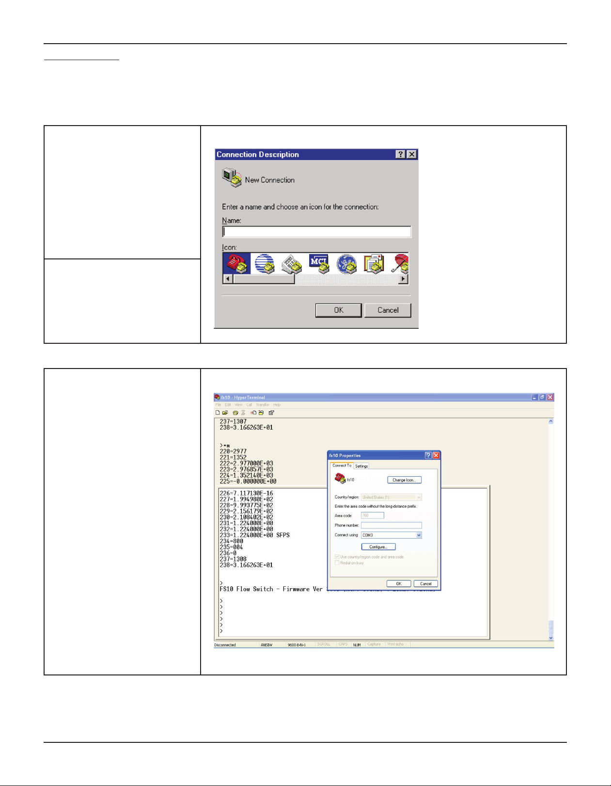
Interface example using HyperTerminal set-up:
HyperTerminal, which comes with Windows95, 98, Me, NT, 2K XP & Windows 7 and can be used to communicated directly with the FS10.
To set up HyperTerminal to interface with computer modem:
1. Start the HyperTerminal .exe program
(hypertrm.exe). Click on START, then
ACCESSORIES, then COMMUNICATIONS, then HYPERTERMINAL, then
choose the HyperTerminal entry that
does not have an .ht extension.
Note: Some Windows versions
store HyperTerminal as an
Accessory.
2. This brings up this dialog.
Enter a name (such as “FS10”)
Select any ICON.
Click OK
3. This dialog will appear. Click the
selection arrow on the “Connect
using” list box, and select the COM
port your modem is connected to –
not the modem name.
When you select the COM port,
the phone number to dial boxes are
grayed.
Click OK
26 Fluid Components International LLC
Page 29

FS10 Series
4. The COM port properties box comes
up. Make sure that you set the Bits
per second to 9600.
The other defaults shown here are
correct.
Click OK.
5. You now get the HyperTerminal window where you are able to control
your modem with commands.
Type *MEAS - you should get these
return values from FS10. You’re ready
to go!
When you end the session, make
sure to say YES to save the settings. A new icon will be created in
the HyperTerminal folder with your
session-name.ht. This is a shortcut
on your desktop for easy access, and
you never need to repeat these setup
steps.
Fluid Components International LLC 27
Page 30

FS10 Series
Command Line Interface Commands
INFO Read version information (Hardware, Firmware, Date code, other values (#1.. #45). [The values in items
1 through 45 are listed]
MEAS Read most recent flow measurement values (#220..#238). [The values in items 220 through 238 are listed]
RCFG B Read configuration parameters (#80..#132) from bank B (0..9). [Example: *RCFG 7 (to read bank 7 parameters)]
SAVE B Save currently active parameters to bank B (0..9) (Level 2 – Field password required). [Example: *SAVE 7]
RCL B Recall parameters from bank B as the active parameters. (Level 2 – Field password required). [Example: *RCL 7]
PASSWD NNNN To enter the password for either Level 1 (Factory) or Level 2 (Field). [Example *PASSWD 19113]
EXIT To exit the current password level (undo having entered a password). The current parameters will automatically be
saved to Bank 0 upon exit.
NNN=<value> Update item #NNN (1..238) in the “active” (RAM) parameters with value. Value may be either integer or floating
point (scientific notation). [Example 1: *228=1.100119E+03 enters value 1.100119E+03 into item 228, Example 2:
*1=002 enters 002 into item1, Example 3: *110=800 enters 800 into item 110]
B:NNN Read item #NNN (1..238) in Bank B (0..9). For items #1..#45, and items #220..#238 the Bank is ignored. If no bank is
specified, the currently active (RAM) parameters will be accessed. [Example 1: *7:85 returns item 85 from bank 7 in
this form: 7:85>5.053665E-02, Example 2: *8:119 returns item 119 from bank 8 in this form: 8:119=030]
28 Fluid Components International LLC
Page 31

FS10 Series
Table 7 RS232 Interface Reference Table
Bank Item # Item Name Description R/W Type Size
1 HW_REV Hardware Version R int 1 N/A
2 FW_REV Firmware Revision R int 1 N/A
3 YY Date Code, Year R int 1 N/A
4 MM Date Code, Month R int 1 N/A
5 DD Date Code, Date R int 1 N/A
6 S_N Sequence Number R int 2 N/A
7 RESERVED1 Reserved 1 int 1
Default
Password
Level
11 FREQ_MAX_OUT For output modes 2, 3, 6, & 7 sets the
maximum frequency output
14 BTN_ENTER_TIMEOUT Keypad lockout time period (sec) R/W int 2 3 Lev 2
35 TAG Customer Tag Number R/W char. 20 Lev 2
36 UNITS_K Conversion factor applied to
flow_final_out to compute
flow_final_units
37 UNITS_ID Units identifier associated with
UNITS_K conversion factor
38 PIPE_ID
39 USER_ID2 User identification field R/W char. 20 Lev 2
40 USER_ID3 User identification field R/W char. 20 Lev 2
41 USER_ID4 User identification field R/W char. 20 Lev 2
45 RTD_TYPE Reference sensor RTD type: 1= 1000
46 NAMUR_ENABLE Enables/Disables NAMUR_Level
User Field: Pipe identification
ohm, 2= 500 ohm, 3= 100ohm
(0=disabled; 1= enabled low, <3.6mA ;
2= enabled high, >21mA)
R/W float 4 2000.0 Lev 2
R/W float 4 1.0 Lev 2
R/W char. 10 SFPS Lev 2
R/W char. 20 Lev 2
R/W int 1 1 Lev 2
R/W int 1 0 Lev 2
50 QSM1_BANK Quick setup mode bank for button 1 R/W int 1 .05 Lev 2
52 QSM1_PERCENT_SPAN Default trip point level as percent of
established span
53 QSM2_BANK Quick setup mode bank for button 2 R/W int 1 .05 Lev 2
55 QSM2_PERCENT_SPAN Default trip point level as percent of
established span
0..9 107 CUST_FLOW_MIN Customer Flow_Final Limit Min. in SFPS R/W float 4 1.224 Lev 2
0..9 108 CUST_FLOW_MAX Customer Flow_Final Limit Max in SFPS R/W float 4 120.0 Lev 2
Fluid Components International LLC 29
R/W float 4 30 Lev 2
R/W float 4 30 Lev 2
Page 32

FS10 Series
Table 7 RS232 Interface Reference Table continued
Password
Bank Item # Item Name Description R/W Type Size
0..9 112 RELAY_LIMIT Relay Limit (SFPS) R/W float 4 65.0 Lev 2
Default
Level
0..9 113 RELAY_HYSTERESIS Relay Hysteresis
(% of #112 [RELAY_LIMIT])
0..9 114 RELAY_HYSTERESIS_
EFFECT
0..9 115 RELAY_POLAR Relay Polarity (1 - Active High,
0..9 116 RELAY_TURN_ON_DELAY Relay Turn-on Delay (secs)
0..9 117 RELAY_TURN_OFF_DELAY Relay Turn-off Delay (secs) 65K secs
0..9 118 DISPLAY_RANGE_MODE Display range either static (0):
0..9 119 INPUT_FILTER_PERIOD Time constant for input filtering (secs) R/W int 1 3 Lev 2
0..9 120 MAX_HYSTERESIS Maximum hysteresis value for
Hysteresis either above or below set
point
0 - Active Low)
65K secs max. Restricted by #121
value when using buttons
max. Restricted by #121 value when
using buttons
based on zero flow and max flow. Or
dynamic (1): based on zero flow, with
auto-adjust (peak hold) for max flow
buttons as % of #112 (trip-point)
R/W float 4 2.0 Lev 2
R/W int 1 0 = below Lev 2
R/W int 1 1 Lev 2
R/W int 1 0 Lev 2
R/W int 1 0 Lev 2
R/W int 1 0 = static Lev 2
R/W float 4 10.0 Lev 2
0..9 121 MAX_DELAY Maximum delay for turn on/
turn off delays (sec); effects
button operation only
0..9 122 FLOW_K1 "K1" factor applied R/W float 4 0.0 Lev 2
0..9 123 FLOW_K2 "K2" factor applied R/W float 4 1.0 Lev 2
0..9 124 FLOW_K3 "K3" factor applied R/W float 4 0.0 Lev 2
0..9 125 FLOW_K4 "K4" factor applied R/W float 4 0.0 Lev 2
0..9 126 CUST_TEMP_MIN Customer Temperature final
Min. limit
0..9 127 CUST_TEMP_MAX Customer Temperature final
Max. limit
220 FLOW_COUNT_RAW Raw ADC Counts for Flow
Sampling
221 REF_COUNT_RAW Raw ADC Counts for
REFERENCE Sampling
222 FLOW_COUNT_ADJ Temp. Compensated Flow ADC counts R float 4 N/A N/A
R/W int 2 10 Lev 2
R/W float 4 0.0 Lev 2
R/W float 4 0.0 Lev 2
R int 2 N/A N/A
R int 2 N/A N/A
30 Fluid Components International LLC
Page 33

FS10 Series
Table 7 RS232 Interface Reference Table continued
Bank Item # Item Name Description R/W Type Size
223 FLOW_COUNT_FILT Adjusted, filtered Flow ADC counts R float 4 N/A N/A
224 REF_COUNT_FILT Adjusted, filtered Ref ADC counts R float 4 N/A N/A
225 dR_OHM Delta R in milliOhm R float 4 N/A N/A
226 REF_OHM Reference R in milliOhm R float 4 N/A N/A
227 dR_OHM_NORM Normalized dR milliOhm R float 4 N/A N/A
228 refR_OHM_NORM Normalized refR milliOhm R float 4 N/A N/A
229 dR_OHM_PCED Power Corrected dR in milliOhm R float 4 N/A N/A
Default
Password
Level
230 dR_OHM_TCED Temp Compensated dR in
milliOhm
231 FLOW_FINAL Temp Comp_ed and N-L
Corrected Flow
232 FLOW_FINAL_OUT
233 FLOW_FINAL_UNITS FLOW_FINAL_OUT adjusted by
234 A_OUT_DAC_COUNT Analog Output DAC Count R int 2 N/A N/A
235 DISPLAY_COUNT COUNT to Be Displayed on LED Bar
236 DIO_BIT_PATTERN LED/Button Bit Pattern R int 2 N/A N/A
237 BOARD_TEMP_COUNT Raw ADC Counts for On-Board Temp
238 REF_TEMP Computed Temperature (deg. F) R float 4 N/A N/A
FLOW_FINAL used for analog output
(adjusted for customer limits)
UNITS_K
Gragh
Sensor Sampling
R float 4 N/A N/A
R float 4 N/A N/A
R float 4 N/A N/A
R float 4 N/A N/A
R int 1 N/A N/A
R int 2 N/A N/A
Fluid Components International LLC 31
Page 34

FS10 Series
6 MAINTENANCE AND TROUBLESHOOTING
Maintenance
ypically required for the sensing element. If the process media sticks to the process pipes (or tank) the sensing element should be cleaned in
the same manner and frequency as the process pipe (or tank). Occasionally check for moisture in the control circuit housing and wiring connections. Check for proper functionality and response time.
Troubleshooting
If the instrument is not operating, go through the installation and adjustment procedures and verify proper installation. If the instrument
fails after some time in service and it has been checked, or if it fails to operate at start up and the installation has been verified, contact your
authorized FCI service representative.
If FCI representative cannot be reached, contact FCI Technical Service. If the instrument is to be returned, obtain a Return Authorization. The
form contains a declaration of decontamination cleaning information that the instrument must comply with before it is shipped to FCI. The
telephone number in the US is 1-800-854-1993 or 1-760-744-6950 or email: techsupport@fluidcomponents.com
32 Fluid Components International LLC
Page 35

FS10 Series
Intentionally Left Blank
Fluid Components International LLC 33
Page 36

FS10 Series
APPENDIX A APPROVALS
EC DECLARATION OF CONFORMITY Model FS10
We, Fluid Components International LLC, located at 1755 La Costa Meadows Drive, San Marcos, California
92078-5115 USA, declare under our sole responsibility that the FS10 Flow Switch Flow Monitor Product
Family, to which this declaration relates, are in conformity with the following standards and Directives.
Directive 94/9/EC ATEX
IECEX Scheme
Certified by KEMA Quality B.V. (0344): Utrechweg 310, 6812 AR, Arnhem, The Netherlands
EC-Type Examination Certificates:
KEMA 10ATEX0142X satisfies EN 60079-0:2009, EN 60079-15:2005, EN 60079-31:2009 requirements for
use in hazardous areas.
IECEx KEM 10.0067X satisfies IEC 60079-0:2007-10, IEC 60079-15:2005-03, IEC 60079-31:2008
requirements for use in hazardous areas.
Hazardous Areas Approval KEMA 10ATEX0142X and IECEx KEM 10.0067X for:
II 3 G Ex nA IIC T4 Gc
II 3 D Ex tc IIIC T81°C Dc
Directive 2004/108/EC EMC
Immunity specification
Emissions specification
Directive 97/23/EC Pressure Equipment
The FS10 Model does not have a pressure bearing housing and is therefore not considered as pressure
equipment by itself according to article 1, section 2.1. The Model FS10 is in conformity with the sound
engineering practices as defined in the Pressure Equipment Directive (PED) 97/23/EC article 3, paragraph 3.
Issued at San Marcos, California USA
September 2011
______________________________________
Eric Wible, Engineering Manager
: EN 61000-6-2: 2005
: EN 61000-6-4: 2007
Eric Wible
2011.09.20
11:53:50 -07'00'
Flow/Liquid Level/Temperature Instrumentation
1755 La Costa Meadows Drive, San Marcos, California 92078 USA 760-744-6950 800-854-1993 760-736-6250
Visit FCI on the Worldwide Web: www.fluidcomponents.com
European Office: Persephonestraat 3-01 5047 TT Tilburg – The Netherlands – Phone 31-13-5159989 Fax 31-13-5799036
Doc no. 23EN000021A
34 Fluid Components International LLC
Page 37

FS10 Series
Intentionally Left Blank
Fluid Components International LLC 35
Page 38

FS10 Series
Safety Instructions for the use the FS10 flowmeter in Hazardous Areas
Approval KEMA 10ATEX0142 X / IECEx KEM 10.0067X for:
Category II 3 G for Gas protection Ex nA IIC T4
Category II 3 D for Dust protection IP64 Ex tc IIIC T 81ºC Dc
The FS10 series consist of a sensing element and associated integral or remote mounted electronics.
Relation between ambient temperature, process temperature and temperature class is as follows:
1) Ambient temperature range (Ta): -40°C … +71°C
2) Maximum process temperature (Tp): 121°C (integral version)
260°C (remote version)
3) Electrical data: Power supply - 21.5…30 VDC, 2.5 Watts Max
Dansk Sikkerhedsforskrifter Italiano Normative di sicurezza
Deutsch Sicherheitshinweise Nederlands Veiligheidsinstructies
English Safety instructions Português Normas de segurança
Υπ Υπ_δεί_εις ασφαλείας
Español Instrucciones de seguridad
Suomi Turvallisuusohjeet Svenska Säkerhetsanvisningar
Français Consignes de sécurité
DK Dansk- Sikkerhedsforskrifter
Disse sikkerhedsforskrifter gælder for Fluid Components, FS10 EF-typeafprøvningsattest-nr. KEMA 10ATEX0142X/IECEx
KEM10.0067(attestens nummer på typeskiltet) er egnet til at blive benyttet i eksplosiv atmosfære kategori II 3 GD.
1) Ex-anlæg skal principielt opstilles af specialiseret personale.
2) FS10 skal jordforbindes.
D A Deutsch-Sicherheitshinweise
Diese Sicherheitshinweise gelten für die Fluid Components, FS10 flowmeter gemäß der EG-Baumusterprüfbescheinigung Nr.
KEMA 10ATEX0142X/IECEx KEM10.0067(Bescheinigungsnummer auf dem Typschild) der Kategorie II 3 GD.
1) Die Errichtung von Ex-Anlagen muss grundsätzlich durch Fachpersonal vorgenommen werden.
2) Der FS10 muß geerdet werden.
GB IRL English- Safety instructions
These safety instructions are valid for the Fluid Components, FS10 flowmeter to the EC type approval certificate no KEMA
10ATEX0142X/IECEx KEM10.0067 (certificate number on the type label) for use in potentially explosive atmospheres in Category II
3 GD.
1) The installation of Ex-instruments must be made by trained personnel.
2) The FS10 must be grounded.
GR Υπ_δεί_εις ασφαλείας
Αυτές οι οδηγίες ασφαλείας ισχύουν για τα Ροόµετρα της Fluid Components τύπου FS10 που φέρουν Πιστοποιητικό Εγκρίσεως
Ευρωπαϊκής Ένωσης, µε αριθµό πιστοποίησης KEMA 10ATEX0142X/IECEx KEM10.0067(ο αριθµός πιστοποίησης βρίσκεται πάνω
στην ετικέτα τύπου του οργάνου) για χρήση σε εκρηκτικές ατµόσφαιρες της κατηγορίας II 3 GD.
1) Η εγκατάσταση των οργάνων µε αντιεκρηκτική προστασία πρέπει να γίνει από εξειδικευµένο προσωπικό.
2) Το όργανο τύπου FS10 πρέπει να είναι γειωµένο.
36 Fluid Components International LLC
Page 39

FS10 Series
FIN Suomi - Turvallisuusohjeet
Nämä turvallisuusohjeet koskevat Flud Components, FS10 EY-tyyppitarkastustodistuksen nro. KEMA 10ATEX0142X/IECEx
KEM10.0067 (todistuksen numero näkyy tyyppikilvestä) käytettäessä räjähdysvaarallisissa tiloissa luokassa II 3 GD.
1) Ex-laitteet on aina asennettava ammattihenkilökunnan toimesta.
2) FS10 on maadoitettava.
F B L Consignes de sécurité
Ces consignes de sécurité sont valables pour le modèle FS10 de la société Fluid Components (FCI) conforme au certificat
d’épreuves de type KEMA 10ATEX0142X/IECEx KEM10.0067(numéro du certificat sur l’étiquette signalétique) conçu pour les
applications dans lesquelles un materiel de la catégorie II3GD est nécessaire.
1) Seul un personnel spécialisé et qualifié est autorisé à installer le matériel Ex.
2) Les FS10 doivent être reliés à la terre.
I Italiano - Normative di sicurezza
Queste normative di sicurezza si riferiscono ai Fluid Components, FS10 secondo il certificato CE di prova di omologazione n° KEMA
10ATEX0142X/IECEx KEM10.0067(numero del certificato sulla targhetta d’identificazione) sono idonei all’impiego in atmosfere
esplosive applicazioni che richiedono apparecchiature elettriche della Categoria II 3 GD.
1) L’installazione di sistemi Ex deve essere eseguita esclusivamente da personale specializzato.
2) I FS10 devono essere collegati a terra.
NL B Nederlands - Veiligheidsinstructies
Deze veiligheidsinstructies gelden voor de Fluid Components, FS10 overeenkomstig de EG-typeverklaring nr. KEMA
10ATEX0142X/IECEx KEM10.0067 (nummer van de verklaring op het typeplaatje) voor gebruik in een explosieve atmosfeer
volgens Categorie II 3GD.
1) Installatie van Ex-instrumenten dient altijd te geschieden door geschoold personeel.
2) De FS10 moet geaard worden.
P Português - Normas de segurança
Estas normas de segurança são válidas para os Fluid Components, FS10 conforme o certificado de teste de modelo N.º KEMA
10ATEX0142X/IECEx KEM10.0067(número do certificado na plaqueta com os dados do equipamento) são apropriados para
utilização em atmosferas explosivas categoria II 3 GD.
1) A instalação de equipamentos em zonas sujeitas a explosão deve, por princípio, ser executada por técnicos qualificados.
2) Os FS10 Flexmasster precisam ser ligados à terra.
E Español - Instrucciones de seguridad
Estas indicaciones de seguridad son de aplicación para el modelo FS10 de Fluid Components, según la certificación CE de modelo
Nº KEMA 10ATEX0142X/IECEx KEM10.0067para aplicaciones en atmósferas potencialmente explosivas según la categoría II 3
GD (el número decertificación se indica sobre la placa informativa del equipo).
1) La instalación de equipos Ex tiene que ser realizada por personal especializado.
2) Los FS10 tienen que ser conectados a tierra.
S Svenska - Säkerhetsanvisningar
Säkerhetsanvisningarna gäller för Fluid Components, Flödesmätare typ FS10 enligt EG-typkontrollintyg nr KEMA
10ATEX0142X/IECEx KEM10.0067 (intygsnumret återfinns på typskylten) är lämpad för användning i explosiv gasblandning i
kategori II 3 GD.
1) Installation av Ex- klassade instrument måste alltid utföras av fackpersonal.
2) FS10 måste jordas.
Fluid Components International LLC 37
Page 40
FS10 Series
APPENDIX B AUXILIARY DRAWINGS
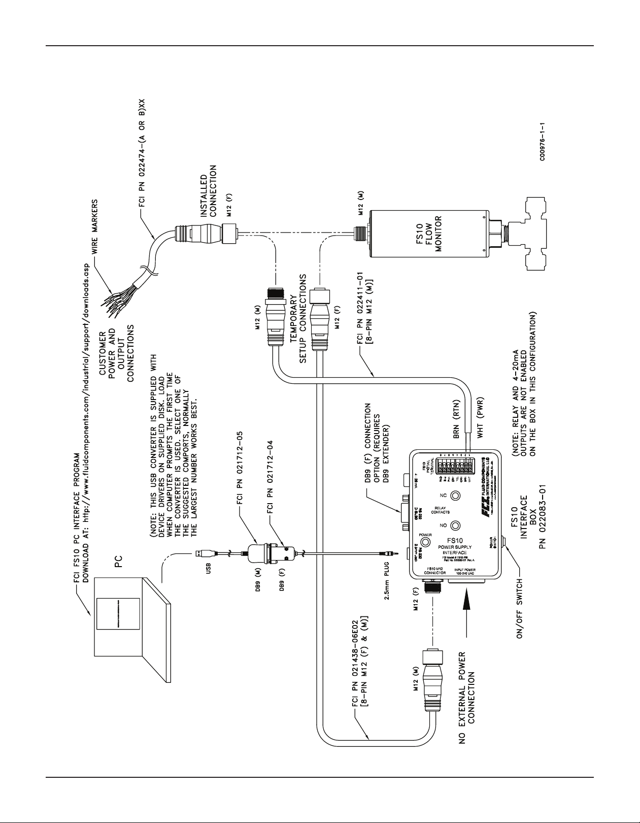
38 Fluid Components International LLC
RS232 Interface Box Hookup - Using Installed DC Power to FS10A
Page 41
FS10 Series
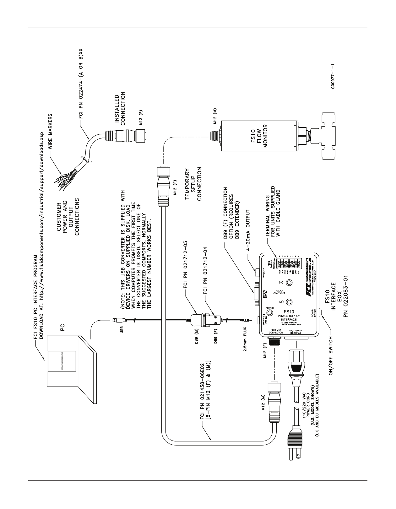
Fluid Components International LLC 39
RS232 Interface Box Hookup - External AC Power Available
Page 42

FS10 Series
40 Fluid Components International LLC
RS232 to Computer Hookup Using Installed Power and Wiring
Page 43

FS10 Series
PC Interface Kits
Fluid Components International LLC 41
Page 44

FS10 Series
022083-01 Power Supply/Interface Box
A
B
C
D
E
F
022083-02 Power Supply/Interface Box Kit
A PN 022083-01 Power Supply/Interface Box
B PN 021712-05 DB9 to USB Converter with USB PC driver disk
C PN 021712-04 2.5mm plug to DB9
D PN 021438-06E02 interconnecting cable, 2 meters, M12(m) and M12(f) end connections
E PN 022411-01 M12 (M) to power leads #1 PWR and #2 RTN
F PN 022421-01 RS232 wire leads to 2.5mm receptacle
FS10 PC interface software 09EN000209
Power cord
42 Fluid Components International LLC
Page 45
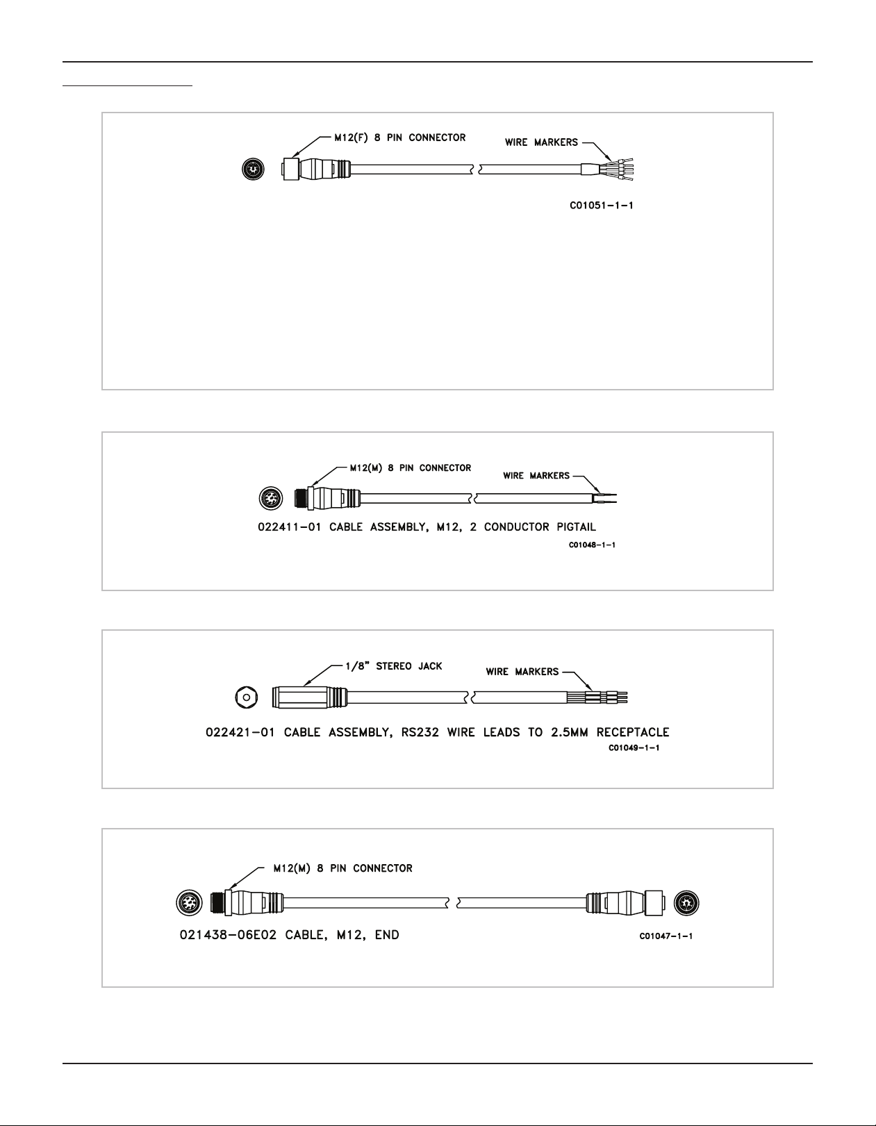
FS10 Series
PC Interface Components
Relay Output
022474-A02 - 8 pin M12(F) connector with 6 feet [2 meter] pigtail and wire markers
022474-A05 - 8 pin M12(F) connector with 15 feet [5 meter] pigtail and wire markers
022474-A10 - 8 pin M12(F) connector with 30 feet [10 meter] pigtail and wire markers
N-Channel MOSFET Output
022474-B02 - 8 pin M12(F) connector with 6 feet [2 meter] pigtail and wire markers
022474-B05 - 8 pin M12(F) connector with 15 feet [5 meter] pigtail and wire markers
022474-B10 - 8 pin M12(F) connector with 30 feet [10 meter] pigtail and wire markers
Power Only to customer M12 installed connector
(Reference auxiliary drawing C00976 - page 33)
(Reference auxiliary drawing C00978 - page 35)
(Reference auxiliary drawings C00976 and C00977 - pages 33 and 34)
Fluid Components International LLC 43
Page 46

FS10 Series
Board Connectors - OEM
44 Fluid Components International LLC
Page 47
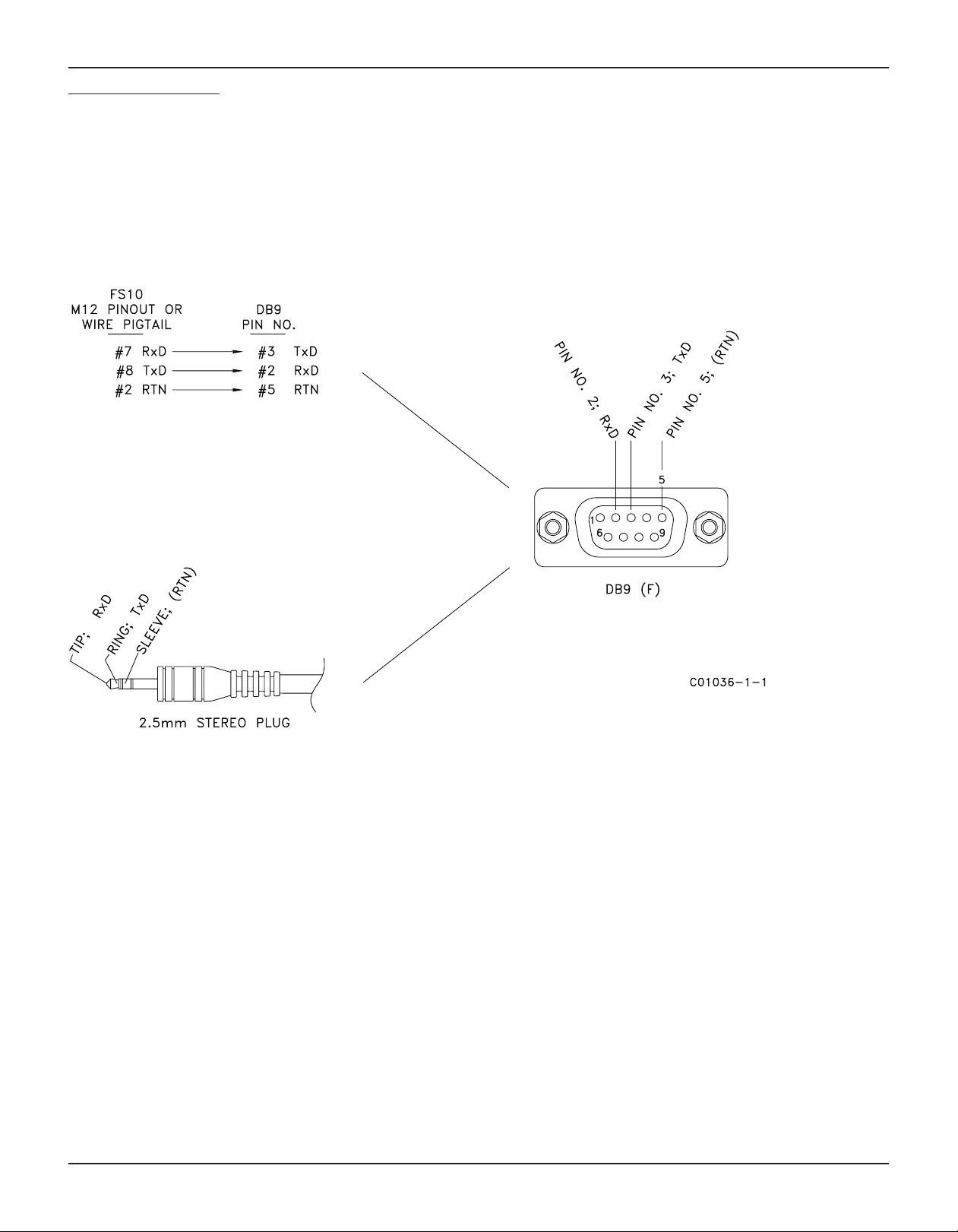
FS10 Series
DB9 Connection Schematic
Wiring Schematic
RS232 from Cable Pigtail to DB9 Female Connector
Wiring Schematic
RS232 through 2.5mm Stereo Plug
to DB9 Female Connector
DB9 Female Connector
Fluid Components International LLC 45
Page 48

FS10 Series
APPENDIX C CUSTOMER SERVICE
Customer Service/ Technical Support
FCI provides full in-house technical support. Additional technical representation is also provided by FCI field representatives. Before
contacting a field or in-house representative, please perform the troubleshooting techniques outlined in this document.
By Mail
Fluid Components International LLC
1755 La Costa Meadows Dr.
San Marcos, CA 92078-5115 USA
Attn: Customer Service Department
By Phone
Contact the area FCI regional representative. If a field representative is unable to be contacted or if a situation is unable to be resolved,
contact the FCI Customer Service Department toll free at 1 (800) 854-1993.
By Fax
To describe problems in a graphical or pictorial manner, send a fax including a phone or fax number to the regional representative.
Again, FCI is available by facsimile if all possibilities have been exhausted with the authorized factory representative. Our Fax number is
1 (760) 736-6250; it is available 7 days a week, 24 hours a day.
By E-Mail
FCI Customer Service can be contacted by e-mail at: techsupport@fluidcomponents.com.
Describe the problem in detail making sure a telephone number and best time to be contacted is stated in the e-mail.
International Support
For product information or product support outside the contiguous United States, Alaska, or Hawaii, contact your country’s FCI
International Representative or the one nearest to you.
After Hours Support
For product information visit FCI at www.fluidcomponents.com. For product support call 1 (800) 854-1993 and follow the prerecorded
instructions.
Point of Contact
The point of contact for service, or return of equipment to FCI is your authorized FCI sales/service office. To locate the office nearest you,
please go to www.fluidcomponents.com.
Warranty Repairs or Returns
FCI prepays ground transportation charges for return of freight to the customer’s door. FCI reserves the right to return equipment by the carrier
of our choice.
International freight, handling charges, duty/entry fees for return of equipment are paid by the customer.
Non-Warranty Repairs or Returns
FCI returns repaired equipment to the customer either collect or prepaid and adds freight charges to the customer invoice.
46 Fluid Components International LLC
Page 49

FS10 Series
Extended Warranty
An extended warranty is available. Please contact the factory for information.
Return to Stock Equipment
The customer is responsible for all shipping and freight charges for equipment that is returned to FCI stock from the customer site. These
items will not be credited to the customer’s account until all freight charges are cleared, along with applicable return to stock charges, from
the credit invoice. (Exceptions are made for duplicate shipments made by FCI.)
If any repair or return equipment is received at FCI, freight collect, without prior factory consent, FCI bills the sender for these charges.
Field Service Procedures
Contact an FCI field representative to request field service.
A field service technician is dispatched to the site from either the FCI factory or one of the FCI representative offices. After the work is complete, the technician completes a preliminary field service report at the customer site and leaves a copy with the customer.
Following the service call, the technician completes a formal, detailed service report. The formal report is mailed to the customer after the
technician’s return to the factory or office.
Field Service Rates
All field service calls are billed at the prevailing rates as listed in the FCI Price Book unless previous arrangements have been made with the
FCI Customer Service Manager.
Customers are charged for all travel expenses including airfare, auto rental, meals and lodging. In addition, the customer shall pay all costs
of transporting parts, tools or goods to and from the job site. Invoicing travel time, field service work and other expenses will be performed by
FCI’s Accounting Department.
Fluid Components International LLC 47
Page 50

FS10 Series
RA #______________
1755 La Costa Meadows Drive, San Marcos, CA 92078-5115 USA
760-744-6950 / 800-854-1993 / Fax: 760-736-6250
Web Site: www.fluidcomponents.com
E-mail: techsupport@fluidcomponents.com
Return Authorization Request
1. Return Customer Information
Returning Company’s Name: _____________________________ Phone# __________________________________
Return Contact Name: __________________________________ Fax # ____________________________________
Email Address: ________________________________________________________________________________
2. Return Address
Bill To: _______________________________________ Ship To: _______________________________________
____________________________________________ ______________________________________________
____________________________________________ ______________________________________________
____________________________________________ ______________________________________________
3. Mandatory End User Information
Contact: ______________________ Company: _____________________________ Country: ________________
4. Return Product Information
Model No: ____________________________________ Serial No(s): ____________________________________
Failure Symptoms
____________________________________________________________________________________________
What Trouble Shooting Was Done Via Phone or Field Visit by FCI: _________________________________________
____________________________________________________________________________________________
FCI Factory Technical Service Contact: _____________________________________________________________
5. Reason For Return Sensor Element Electronics As Found Testing Credit
(Note: A new Application Data Sheet (ADS) must be submitted for all recalibrations and re-certifications)
(Detailed Description Required)
Recalibrate (New Data) Recalibrate (Most Recent Data) Other
: ____________________________________________________
6. Payment Via Faxed Purchase Order
(Note: A priced quotation is provided for all Non-Warranty repairs after equipment has been evaluated. All Non-Warranty repairs
are subject to a minimum evaluation charge of $250.00)
Factory Return Shipping Address: Fluid Components International LLC
1755 La Costa Meadows Drive
San Marcos, CA 92078-5115
Attn: Repair Department
RA #____________
48 Fluid Components International LLC
Page 51

FS10 Series
The following Return Authorization Request form and Decontamination Statement
before
a Return Authorization Number will be issued. The signed Decontamination Statement and applicable MSDS Sheets must be in-
cluded with the shipment. FCI will either fax, email or telephone you with the Return Authorization Number upon receipt of the signed
forms.
Packing Procedures
1. Electronics should be wrapped in an anti-static or static-resistant bag, then wrapped in protective bubble wrap and surrounded
with appropriate dunnage* in a box. Instruments weighing more than 50 lbs., or extending more than four feet, should be secured in wooden crates by bolting the assemblies in place.
2. The sensor head must be protected with pvc tubing, or retracted the full length of the probe, locked and secured into the Packing Gland Assembly (cap screws tightened down).
3. FCI can supply crates for a nominal fee.
4. No more than four (4) small units packaged in each carton.
5. FCI will not be held liable for damage caused during shipping.
6. To ensure immediate processing mark the RA number on the outside of the box. Items without an RA number marked on the box
or crate may be delayed.
7. Freight must be “PrePaid” to FCI receiving door.
* Approriate dunnage as defined by UPS, will protect package contents from a drop of 3 feet.
MUST be completed, signed and faxed back to FCI
*** Decontamination Statement *** This Section Must Be Completed ***
Exposure to hazardous materials is regulated by Federal, State, County and City laws and regulations. These laws provide FCI’s
employees with the “Right to Know” the hazardous or toxic materials or substances in which they may come in contact while handling returned products. Consequently, FCI’s employees must have access to data regarding the hazardous or toxic materials or
substances the equipment has been exposed to while in a customer’s possession. Prior to returning the instrument for evaluation/
repair, FCI requires thorough compliance with these instructions. The signer of the Certificate must be either a knowledgeable Engineer, Safety Manager, Industrial Hygenist or of similar knowledge or training and responsible for the safe handling of the material to
which the unit has been exposed. Returns without a legitimate Certification of Decontamination, and/or MSDS when required, are
unacceptable and shall be returned at the customer’s expense and risk. Properly executed Certifications of Decontamination must
be provided before a repair authorization (RA) number will be issued.
Certification Of Decontamination
I certify that the returned item(s) has(have) been thoroughly and completely cleaned. If the returned item(s) has(have) been exposed to hazardous or toxic materials or substances, even though it (they) has (have) been thoroughly cleaned and decontaminated,
the undersigned attests that the attached Material Data Safety Sheet(s) (MSDS) covers said materials or substances completely.
Furthermore, I understand that this Certificate, and providing the MSDS, shall not waive our responsibility to provide a neutralized,
decontaminated, and clean product for evaluation/repair at FCI. Cleanliness of a returned item or acceptability of the MSDS shall
be at the sole discretion of FCI. Any item returned which does not comply with this certification shall be returned to your location
Freight Collect and at your risk.
This certification must be signed by knowledgeable personnel responsible for maintaining or managing the safety program at
your facility.
Process Flow Media _____________________________________________________________________________________
Product was or may have been exposed to the following substances: _______________________________________________
Print Name_____________________________________________________________________________________________
Authorized Signature ___________________________________________ Date _____________________________________
Company Title __________________________________________________________________________________________
Visit FCI on the Worldwide Web: www.fluidcomponents.com
1755 La Costa Meadows Drive, San Marcos, California 92078-5115 USA ‡ Phone: 760-744-6950 ‡ 800-854-1993 ‡ Fax: 760-736-6250
FCI Document No. 05CS000004D [U]
Fluid Components International LLC 49
Page 52

FS10 Series
WARRANTIES
Goods furnished by the Seller are to be within the limits and of the sizes published by the Seller and subject to the
Seller’s standard tolerances for variations. All items made by the Seller are inspected before shipment, and should
any of said items prove defective due to faults in manufacture or performance under Seller approved applications,
or fail to meet the written specifications accepted by the Seller, they will be replaced or repaired by Seller at no
charge to Buyer provided return or notice of rejection of such material is made within a reasonable period but in no
event longer than three (1) years for non-calibration defects and one (1) year for calibration defects from date of shipment to Buyer, and provided further, that an examination by Seller discloses to Seller’s reasonable satisfaction that
the defect is covered by this warranty and that the Buyer has not returned the equipment in a damaged condition
due to Buyer’s or Buyer’s employees’, agents’, or representatives’ negligence and Buyer has not tampered, modified,
redesigned, misapplied, abused, or misused the goods as to cause the goods to fail. In addition, this warranty shall
not cover damage caused by Buyer’s exposure of the goods to corrosive or abrasive environments. Moreover, Seller
shall in no event be responsible for (1) the cost or repair of any work done by Buyer on material furnished hereunder
(unless specifically authorized in writing in each instance by Seller), (2) the cost or repair of any modifications added
by a Distributor or a third party, (3) any consequential or incidental damages, losses, or expenses in connection with
or by reason of the use of or inability to use goods purchased for any purpose, and Seller’s liability shall be specifically limited to free replacement, or refund of the purchase price, at Seller’s option, provided return or rejection of the
goods is made consistent with this paragraph, and the Seller shall in no event be liable for transportation, installation,
adjustment, loss of good will or profits, or other expenses which may arise in connection with such returned goods,
or (4) the design of products or their suitability for the purpose for which they are intended or used. Should the Buyer
receive defective goods as defined by this paragraph, the Buyer shall notify the Seller immediately, stating full particulars in support of his claim, and should the Seller agree to a return of the goods, the Buyer shall follow Seller’s
packaging and transportation directions explicitly. In no case are the goods to be returned without first obtaining a
return authorization from the Seller. Any repair or replacement shall be at Seller’s factory, unless otherwise directed,
and shall be returned to Seller transportation prepaid by Buyer. If the returned goods shall prove defective under this
clause they will be replaced or repaired by Seller at no charge to Buyer provided the return or rejection of such material is made within a reasonable period, but in no event longer than (1) year from the date of shipment of the returned
goods or the unexpired terms of the original warranty period whichever is later. If the goods prove to be defective
under this paragraph, the Buyer shall remove the goods immediately from the process and prepare the goods for
shipment to Seller. Continued use or operation of defective goods is not warranted by Seller and damage occurring
due to continued use or operation shall be for Buyer’s account. Any description of the goods contained in this offer
is for the sole purpose of identifying them, and any such description is not part of the basis of the bargain, and does
not constitute a warranty that the goods will conform to that description. The use of any sample or model in connection with this offer is for illustrative purposes only, is not part of the basis of the bargain, and is not to be construed
as a warranty that the goods will conform to the sample or model. No affirmation of that fact or promise made by the
Seller, whether or not in this offer, will constitute a warranty that the goods will conform to the affirmation or promise. THIS WARRANTY IS EXPRESSLY IN LIEU OF ANY AND ALL OTHER EXPRESS OR IMPLIED WARRANTIES WITH
RESPECT TO THE GOODS OR THEIR INSTALLATION, USE, OPERATION, REPLACEMENT OR REPAIR, INCLUDING ANY
IMPLIED WARRANTY OF MERCHANTABILITY OR FITNESS OF PURPOSE; AND THE GOODS ARE BEING PURCHASED
BY BUYER “AS IS”. SELLER WILL NOT BE LIABLE BY VIRTUE OF THIS WARRANTY OR OTHERWISE FOR ANY SPECIAL,
INCIDENTAL OR CONSEQUENTIAL LOSS OR DAMAGE RESULTING FROM THE USE OR LOSS OF USE OF THE GOODS.
50 Fluid Components International LLC
Page 53

FS10 Series
NOTES
Fluid Components International LLC 51
Page 54

FS10 Series
FCI’s Complete Customer Commitment. Worldwide
ISO 9001 and AS9100 Certified
Visit FCI on the Worldwide Web: www.fluidcomponents.com
FCI World Headquarters
1755 La Costa Meadows Drive | San Marcos, California 92078 USA | Phone: 760-744-6950 Toll Free (US): 800-854-1993 Fax: 760-736-6250
FCI Europe
Persephonestraat 3-01 | 5047 TT Tilburg, The Netherlands | Phone: 31-13-5159989 Fax: 31-13-5799036
FCI Measurement and Control Technology (Beijing) Co., LTD | www.fluidcomponents.cn
Room 107, Xianfeng Building II, No.7 Kaituo Road, Shangdi IT Industry Base, Haidian District | Beijing 100085, P. R. China
Phone: 86-10-82782381 Fax: 86-10-58851152
This document contains confidential technical data, including trade secrets and proprietary information which is the property of Fluid
Components International LLC (FCI). Disclosure of this data to you is expressly conditioned upon your assent that its use is limited to use within your
company only (and does not include manufacture or processing uses). Any other use is strictly prohibited without the prior written consent of FCI.
Notice of Proprietary Rights
© Copyright 2011 by Fluid Components International LLC. All rights reserved. FCI is a registered trademark of Fluid Components International LLC. Information subject to change without notice.
Fluid Components International LLC 06EN003394 Rev. D
 Loading...