

Page 1
Installation, Operation and Maintenance
®TM
Nuclear Qualifi ed FLT 93
Flow, Level, Temperature Switch/Monitor
Models: FLT93F, FLT93L, FLT93S
Series FlexSwitch
[
]
Doc 06EN003409
Page 2

FLT® Series FlexSwitch
TM
This document contains confi dential technical data, including trade secrets and proprietary information which is the property of Fluid
Notice of Proprietary Rights
Components International LLC (FCI). Disclosure of this data to you is expressly conditioned upon your assent that its use is limited to use within your company only (and does not include manufacture or processing uses). Any other use is strictly prohibited without the prior written consent of FCI.
© Copyright 2011 by Fluid Components International LLC. All rights reserved.
Manufactured in accordance with one or more of the following patents: 5,600,528; 6,340,243. FCI is a registered trademark of Fluid Components International LLC. Information subject to change without notice.
Fluid Components International LLC
Page 3

FLT® Series FlexSwitchTM 06EN003409 Rev. -
Table of Contents
1 GENERAL ...................................................................................................................................................................................................7
Description................................................................................................................................................................................................................... 7
Theory of Operation ..................................................................................................................................................................................................... 7
Sensing Element .......................................................................................................................................................................................................... 7
Control Circuit .............................................................................................................................................................................................................. 7
Technical Specifi cation ................................................................................................................................................................................................ 8
2 INSTALLATION .........................................................................................................................................................................................11
Receiving/Inspection ................................................................................................................................................................................................... 11
Packing/Shipping/Returns ........................................................................................................................................................................................... 11
Factory Calibration Note.............................................................................................................................................................................................. 11
Pre-Installation Procedure ........................................................................................................................................................................................... 11
Use Standard ESD Precautions ................................................................................................................................................................................ 11
Prepare or Verify Sensing Element Location ............................................................................................................................................................ 11
Verify Dimensions .................................................................................................................................................................................................... 11
Verify Sensing Element Flow Direction and Placement Orientation (Flow Application) ......................................................................................... 11
Verify Sensing Element Flow Direction and Placement Orientation (Level Application) ........................................................................................ 12
Install the Sensing Element......................................................................................................................................................................................... 12
Male NPT Mounting ................................................................................................................................................................................................. 12
Flange Mounting ...................................................................................................................................................................................................... 12
Packing Gland Assembly .......................................................................................................................................................................................... 13
In-line NPT Assembly (FLT93-L) ............................................................................................................................................................................... 13
Install and Wire the Enclosure(s) ............................................................................................................................................................................. 14
Minimum Wire Size.................................................................................................................................................................................................. 14
Enclosures Covers .................................................................................................................................................................................................... 14
Cable and Conduit Entry Devices ............................................................................................................................................................................. 14
Wiring the Local Enclosure ..................................................................................................................................................................................... 15
Wiring The Remote Enclosure.................................................................................................................................................................................. 15
Locate the Remote Hardware Location.................................................................................................................................................................... 15
Wiring Remote Enclosure with Auxiliary Relay ....................................................................................................................................................... 16
Wiring A Remote Control Circuit To An Auxiliary Relay Board ................................................................................................................................ 16
Wiring Output Signal Terminals .................................................................................................................................................................................. 17
3 OPERATION ...............................................................................................................................................................................................19
Factory Default Jumper Confi guration ........................................................................................................................................................................ 19
Confi guration Jumpers ................................................................................................................................................................................................ 19
Heater Cut-Off ............................................................................................................................................................................................................. 19
Alarm Set Point Adjustments ...................................................................................................................................................................................... 20
Numerical Adjustment Versus Adjustment by Observation .................................................................................................................................... 20
Numerical Alarm Set Point Adjustment ...................................................................................................................................................................... 22
Air/Gas Flow Applications ....................................................................................................................................................................................... 22
Wet/Dry Liquid Level Applications .......................................................................................................................................................................... 24
Liquid Flow Applications .......................................................................................................................................................................................... 26
Adjustment by Observation ......................................................................................................................................................................................... 28
Flow Applications ..................................................................................................................................................................................................... 28
Fluid Components International LLC 3
Page 4

06EN003409 Rev. - FLT® Series FlexSwitch
TM
Level Applications .................................................................................................................................................................................................... 28
Temperature Applications ........................................................................................................................................................................................ 29
Converting Temp Out Voltage to Temperature in Degrees F or Degrees C .............................................................................................................. 31
Fail Safe Alarm Setting .............................................................................................................................................................................................. 37
Low Flow Alarm Settings ......................................................................................................................................................................................... 37
High Flow Alarm Settings ........................................................................................................................................................................................ 37
Low Level Alarm Settings (Sensing Element Normally Wet) ................................................................................................................................. 38
High Level Alarm Settings (Sensing Element Normally Dry) .................................................................................................................................. 38
4 MAINTENANCE .......................................................................................................................................................................................39
Maintenance ................................................................................................................................................................................................................ 39
Calibration ................................................................................................................................................................................................................ 39
Electrical Connections .............................................................................................................................................................................................. 39
Remote Enclosure ..................................................................................................................................................................................................... 39
Electrical Wiring ....................................................................................................................................................................................................... 39
Sensing Element Connections.................................................................................................................................................................................. 39
Sensing Element Assembly ...................................................................................................................................................................................... 39
5 TROUBLESHOOTING .............................................................................................................................................................................. .41
Tools Needed ............................................................................................................................................................................................................ 41
Quick Check .............................................................................................................................................................................................................. 41
Non-maintenance Observations............................................................................................................................................................................... 41
Check Serial Numbers .............................................................................................................................................................................................. 41
Check Input Power .................................................................................................................................................................................................... 41
Check the Instrument Installation ............................................................................................................................................................................ 41
Check for Moisture ................................................................................................................................................................................................... 41
Check Application Design Requirements ................................................................................................................................................................. 41
Troubleshooting the Flow Element .............................................................................................................................................................................. 42
Troubleshooting the Flow Transmitter ......................................................................................................................................................................... 43
Spares ....................................................................................................................................................................................................................... 44
Defective Parts ......................................................................................................................................................................................................... 44
Customer Service ..................................................................................................................................................................................................... 44
4 Fluid Components International LLC
Page 5

FLT® Series FlexSwitchTM 06EN003409 Rev. -
APPENDIX A DRAWINGS ........................................................................................................................................................................ .45
APPENDIX B GLOSSARY ..........................................................................................................................................................................47
APPENDIX C TEMPERATURE COMPENSATION ...................................................................................................................................49
Introduction .................................................................................................................................................................................................................. 49
Factory Temperature Compensation Settings ............................................................................................................................................................. 49
Field Temp Comp Calibration ....................................................................................................................................................................................... 50
APPENDIX D CUSTOMER SERVICE ........................................................................................................................................................53
Customer Service/ Technical Support ...................................................................................................................................................................... 53
Warranty Repairs or Returns .................................................................................................................................................................................... 53
Non-Warranty Repairs or Returns ............................................................................................................................................................................ 53
Return to Stock Equipment....................................................................................................................................................................................... 54
Field Service Procedures .......................................................................................................................................................................................... 54
Field Service Rates ................................................................................................................................................................................................... 54
Return Authorization Request ................................................................................................................................................................................ 55
Fluid Components International LLC 5
Page 6

FLT® Series FlexSwitch
TM
INTENTIONALLY LEFT BLANK
6 Fluid Components International LLC
Page 7
FLT® Series FlexSwitchTM GENERAL
1 GENERAL
Description
The FLT Series models are multipurpose measurement instruments. The FLT Series models that are included in this manual are FLT93-S, FLT93-F,
FLT93-HT and FLT93-L. Each model is a single instrument that is capable of detecting fl uid fl ow and temperature. It is also able to detect liquid level
or fl uid media interfaces. The instrument has two fi eld adjustable alarm set points, two buffered voltage outputs, as well as a built-in calibration
circuit. The output of the alarm set points are 6 amp relay contacts that can be used to control customer process applications. An optional 10 amp
relay contacts can be used to control the customer process application. One buffered voltage output is available for fl ow or level monitoring and the
second buffered voltage output is available for temperature monitoring.
Theory of Operation
The fl ow switch is a fi xed position, single-point fl ow, level, interface and temperature switch. The operation of the sensing element is based upon
the thermal dispersion principle: A low-powered heater is used to produce a temperature differential between two Resistance Temperature Detectors (RTDs). The RTD temperature differential varies as a function of forced convection for fl ow measurement and as a function of fl uid thermal
conductivity for level and interface measurement. The measurement of the fl uid’s temperature is obtained from the non-heated RTD.
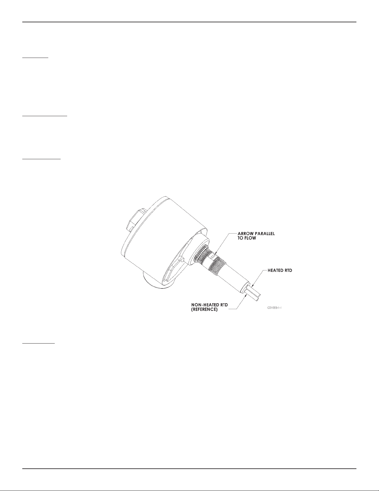
Sensing Element
The sensing element consists of two thermowells (hollow tubes) that when inserted into the fl ow process allows an unimpeded fl ow inside the
process line. The top thermowell has a self-heated RTD inserted into it. The bottom thermowell has a reference RTD inserted into it. In order to
correctly orient the sensing element a fl ow arrow has been etched onto the threaded portion of the sensing element. See Figure 1-1 for a view of the
sensing element.
Figure 1-1 View of the Sensing Element
Control Circuit
The control circuit converts the sensing element’s RTD temperature differential into an analog DC voltage signal. Dual comparators monitor the
sensing element signal and activates the relay alarm circuits if the signal exceeds an adjustable set point.
The control circuit contains fi eld removable jumpers that confi gures the instrument to perform in the fi eld as needed by the customer.
Fluid Components International LLC 7
Page 8

TECHNICAL SPECIFICATIONS FLT® Series FlexSwitch
Technical Speci cation
TM
Application
Flow rate and /or level /interface and temperature sensing in liquid,
gas and slurry applications.
Sensing Elements
Process Connection
Models S and F
3/4 inch male NPT standard; optional 1 inch BSP, 1 inch male
NPT, 3/4 inch Male NPT (FLT93-F only); fl anges, or spool pieces.
Model L
1” male NPT or 3/4” female NPT, both ends with orifi ce;
fl anges optional.
Insertion Length
Models S and F
Available in standard lengths of 1.2” [30mm], 2” [51mm],
4” [102mm], 6” [152mm], 9” [229mm], 12” [305mm],
18” [457mm] and custom-specifi ed lengths.
Model L
3.375” [86mm] in-line body length
Sensing Element
Models S and F
All wetted surfaces are 316L stainless steel with all-welded
construction. Hastelloy C, Monel 400, electro-polished
stainless steel and titanium (FLT93-S only) are optionally
available.
Model L
All wetted surfaces are 316L stainless steel with all-welded
construction. Hastelloy C, Monel 400 and titanium are
optionally available.
Operating Temperature
Sensing Element:
All Models
Standard temperature confi guration:
-40°F to +350°F [-40°C to +177°C]
Medium temperature confi guration:
-100°F to +500°F [-73°C to +260°C]
Model S Only
High temperature confi guration:
-100°F to +850°F [-73°C to +454°C]
Control Circuit:
All Models
Ambient -40°F to +140°F [-40°C to + 60°C]
Operating Pressure
Models S, F and L
2350 psig [ 162 bar(g)] maximum at 500°F [260°C]
1450 psig [100 bar(g)] maximum at 850°F [454°C]
Control Circuit Features
Control Circuit
Standard: Plug-in, socket mounted with dual alarm/trip epoxy sealed
relays.
Optional: Rack-mount confi guration (card cage or enclosure not
included)
Output Signal
Analog DC voltage related to fl ow or level / interface signal and
proportional to temperature, standard.
Input Power
Field selected or pre-confi gured in the factory to 115 Vac (±15),
230 Vac (±30, 50 to 60 Hz), 24 Vdc (+4, -3) or 24 Vac (+2, -6);
100 Vac ±10 optionally available. LED indicates power on.
Power Consumption
AC units, 13 VA maximum; DC units, 7 watts maximum.
Heater Power
Field or factory selected to optimize switching performance and
rangeability and selectable for specifi c fl uid service requirements.
7 watts power consumption, 230 mA maximum.
Typical Service Sensing Element Power (W)
Gas or Air S-Style 0.75
F-Style 0.25
Liquids S-Style 3.0
The above typical service power selections are for reference
only. Depending on application requirements, surface temperature
rating requirements, and rangeability expectations, alternate power
selections may be recommended. Other intermediate power selections can be made. Consult installation manual for recommendations
in your service.
Relay Rating
Dual SPDT or single DPDT fi eld confi gurable 6 amp resistive at 115
Vac, 240 Vac or 24 Vdc; hermetically sealed relay confi gurations
optionally available.
Electrical Enclosure
Aluminum (epoxy coated) or optional stainless steel. Enclosures are
rated for hazardous location use (Class I and II, Division 1 and 2,
Group B, C, D, E, F and G; and EEx d IIC) and resists the effect of
weather and corrosion (NEMA and CSA Type 4X and equivalent to
IP66).
For Flow Service
Setpoint Range
Model S
Water-based Liquids:
0.01 FPS to 0.5 FPS [0.003 MPS to 1.52 MPS]with 0.75 watt heater;
0.01 FPS to 3.0 FPS [0.003 MPS to 0.9 MPS] with 3.0 watt heater.
Hydrocarbon-based Liquids:
0.01 FPS to 1.0 FPS [0.003 MPS to 0.3 MPS] with 0.75 watt heater;
0.01 FPS to 5.0 FPS with [0.003 MPS to 1.5 MPS] with 3.0 watt
heater.
Air/Gas:
0.25 SFPS to 120 SFPS [0.08 NMPS to 37 NMPS] with 0.75 watt
heater at standard conditions; 70°F [21.1°C], 14.7 psia [1.013
bar(g)].
Other Fluids: Contact the factory for approximate rangeability.
Model F
Air/Gas:
0.25 SFPS to 120 SFPS [0.08 NMPS to 37 NMPS] 0.75 watt heater
at standard conditions; 70°F [21.1°C], 14.7 psig [1.013 bar(g)].
Model L
Water-based Liquids: 0.015 cc/sec to 50 cc/sec
Hydrocarbon-based Liquids: 0.033 cc/sec to 110 cc/sec
Air/Gas: 0.6 cc/sec to 20,000 cc/sec
8 Fluid Components International LLC
Page 9

FLT® Series FlexSwitchTM TECHNICAL SPECIFICATIONS
Factory Calibrated Switch Point Accuracy
Any fl ow rate within the instrument fl ow range may be selected as a
setpoint alarm. A factory-calibrated setpoint adjustment may be
optimally preset with accuracy of ±2% of setpoint velocity over an
operating temperature range of ±50°F [±28°C].
Monitoring Accuracy
Based on a measured output voltage over the entire fl ow range, an
operating temperature range of ±50°F [±28°C], and an operating
pressure range of ±100 psig [±7 bar(g)]:
Liquids: ±5% reading or ±0.04 SFPS [±0.012 NMPS],
whichever is larger
Gases: ±5% reading or ±2 SFPS [±0.61 NMPS], whichever is larger
Repeatability
±0.5% reading
For Level/Interface Service
Accuracy
Model S
±0.25° [±6.4 mm]
Model F
±0.1° [±2.5 mm]
Repeatability
Model S
±0.125° [±3.2 mm]
Model F
±0.05° [±1.3 mm]
Nuclear Safety Certi cation
FLT93 sensor elements were qualifi ed for harsh environment applications under the guidelines of iEEE-323, iEEE-344 and iEEE-382.
Radiation Exposure
Models S and F
2x10⁸ rads
High Temperature
5x10⁷ rads
Electronics Module [5294] qualifi ed for radiation harsh
5x10⁵ rads
Seismic Level
Models S and F
3g ZPA’s
High Temperature
8g ZPA’s
Shipping Weight (approximate)
Integral: 8 lb [3.6 kg]
Remote: 13 lb [5.9 kg]
For Temperature Service
Accuracy
±2.0°F [±1°C] with fi eld setpoint adjustment. Monitoring accuracy
±3.5°F [±2°C] with standard curve fi t output voltage operation
across the selected instrument temperature range. Higher accuracy
available with factory calibrations.
Repeatability
±1.0°F [±0.6°C]
The above accuracy is based on liquid or slurry service and in
gas service with a minimum 1 SFPS [0.3 NMPS] velocity past the
sensing element or with the heater deactivated for temperature
sensing service only.
MTBF: 190 years
SIL: SIL-2 compliant, safe failure fraction (SFF) 82% to 84%
Factory Application-Speci c Set-up and
Setpoint Calibration
Standard instrument factory default setting, unless otherwise
selected at order entry, will be as follows:
• 115 Vac input power for all FM Approved units. 230 Vac for all
other agency approval units.
• Dual SPDT alarms set for:
• Alarm No. 1: Preset for fl ow or level and to de-energize with
decreasing conditions.
• Alarm No. 2: Preset to de-energize for increasing temperature at
10 °F [5 °C] below the maximum instrument process temperature.
• Heater power at 0.25 watt on Model F or 0.75 watt on Model S.
• Calibration switch set at “operate.”
Factory calibration including set-up for specifi c service, process
fl uid and alarm conditions optionally available. Contact factory for
fl uid handling capabilities.
Fluid Components International LLC 9
Page 10

FLT® Series FlexSwitch
TM
INTENTIONALLY LEFT BLANK
10 Fluid Components International LLC
Page 11

FLT® Series FlexSwitchTM INSTALLATION
2 INSTALLATION
Receiving/Inspection
• Unpack carefully.
• Verify that all items in the packing list are received and are correct.
• Inspect all instruments for damage or contaminants prior to installation.
If the above three items are satisfactory, proceed with the installation. If not, then stop and contact a customer service representative.
Packing/Shipping/Returns
These issues are addressed in Appendix D - Customer Service.
Factory Calibration Note
The instrument is factory calibrated to the applications as specifi ed at the time of order. There is no need to perform any verifi cation or
calibration steps prior to installing and placing the instrument in service unless the application has been varied.
Pre-Installation Procedure
Warning: Only qualifi ed personnel should install this instrument. Install and follow safety procedures in accordance with the current
National Electrical Code. Ensure that power is off during installation. Any instances where power is applied to the instrument will be noted in this manual. Where the instructions call for the use of electrical current, the operator assumes all
responsibility for conformance to safety standards and practices.
Caution: The instrument contains electrostatic discharge (ESD) sensitive devices. Use standard ESD precautions when handling the
control circuit. See below, for ESD details.
The instrument is not designed for weld-in-place applications. Never weld to a process connection or a structural support.
Damage resulting from moisture penetration of the control circuit or fl ow element enclosure is not covered by product warranty.
Use Standard ESD Precautions
Use standard ESD precautions when opening an instrument enclosure or handling the control circuit. FCI recommends the use of the following precautions: Use a wrist band or heel strap with a 1 megohm resistor connected to ground. If the instrument is in a shop setting there
should be static conductive mats on the work table and fl oor with a 1 megohm resistor connected to ground. Connect the instrument to
ground. Apply antistatic agents to hand tools to be used on the instrument. Keep high static producing items away from the instrument such
as non-ESD approved plastic, tape and packing foam.
The above precautions are minimum requirements to be used. The complete use of ESD precautions can be found in the U.S. Department Of
Defense Handbook 263.
Prepare or Verify Sensing Element Location
Prepare the process pipe for installation, or inspect the already prepared location to ensure that the instrument will fi t into the system.
Review the requirement for the supply power and alarm circuit connections.
Verify Dimensions
Verify the instrument’s dimensions versus the process location to be sure of a correct fi t. Also see Appendix A for dimensions.
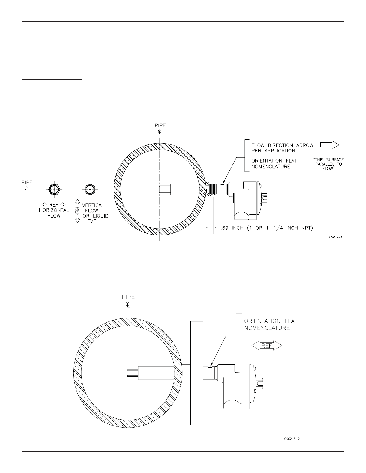
Verify Sensing Element Flow Direction and Placement Orientation (Flow Application)
For fl ow detection, the sensing element surface marked with direction arrows should be oriented parallel to the process fl ow. The fl ow can
be from either direction.
Mount the sensing element at least 20 diameters downstream and 10 diameters upstream from any bends or interference in the process pipe
or duct to achieve the greatest accuracy.
For liquid fl ow service, the sensing element should be located in the process pipe so that the thermowells are always completely wet.
When mounted in a tee or section of pipe larger than the normal process pipe, position in a vertical run of pipe with fl ow upward. This will
prevent air or gas bubbles from becoming trapped at the sensor assembly.
Vertical positioning with fl ow downward is only recommended for higher fl ow rate applications (consult FCI).
Fluid Components International LLC 11
Page 12
INSTALLATION FLT® Series FlexSwitch
Verify Sensing Element Flow Direction and Placement Orientation (Level Application)
If the sensing element is side-mounted on the process vessel, then the surface marked with direction arrows should be vertically oriented.
If the sensing element is top- or bottom-mounted on the process vessel, the orientation of the surface marked with direction arrows does not
matter.
Install the Sensing Element
Male NPT Mounting
When mounting the sensing element to the process pipe, it is important that a lubricant/sealant be applied to the male threads of all connections. Be sure to use a lubricant/sealant compatible with the process environment. All connections should be tightened fi rmly. To avoid
leaks, do not overtighten or cross-thread connections. See Figure 2-1 for proper mounting.
TM
Figure 2-1 NPT Pipe Thread Mount
Flange Mounting
For fl ange mounted sensing elements, attach the process mating fl ange with care. The correct orientation of the sensing element must be
maintained to ensure optimum performance or calibration. See Figure 2-2.
Figure 2-2 Flange Mount
12 Fluid Components International LLC
Page 13
FLT® Series FlexSwitchTM INSTALLATION
Packing Gland Assembly
1. Threaded or fl anged packing gland mounts are available. The valve assembly with appropriate connections are customer supplied. Follow the male NPT mounting procedure above to attach the pipe thread portion or fl ange mounting portion as applicable.
2. Tighten the packing nut until the internal packing is tight enough so that the friction fi t on the shaft is adequate to prevent leakage but
not prevent the shaft from sliding. Position the etched fl ow arrow parallel with the fl ow (±1° of level) and position the fl ow arrow so it is
pointing in the direction of the fl ow.
3. Proceed to insert the probe into the process media line. Use the adjusting nuts on the all-thread to pull the sensing element into proper
predetermined depth position.
4. Tighten the opposing lock nuts on the all-threads. Tighten the packing nut another half to full turn until tight (approximately 65 to 85
ft-lbs [88 to 115 N-m] torque).
5. Rotate the split ring locking collar to line up with the connecting strap welded to the packing nut. Tighten the two 1/4-28 hex socket cap
screws on the split ring locking collar.
Reverse these steps for removal.
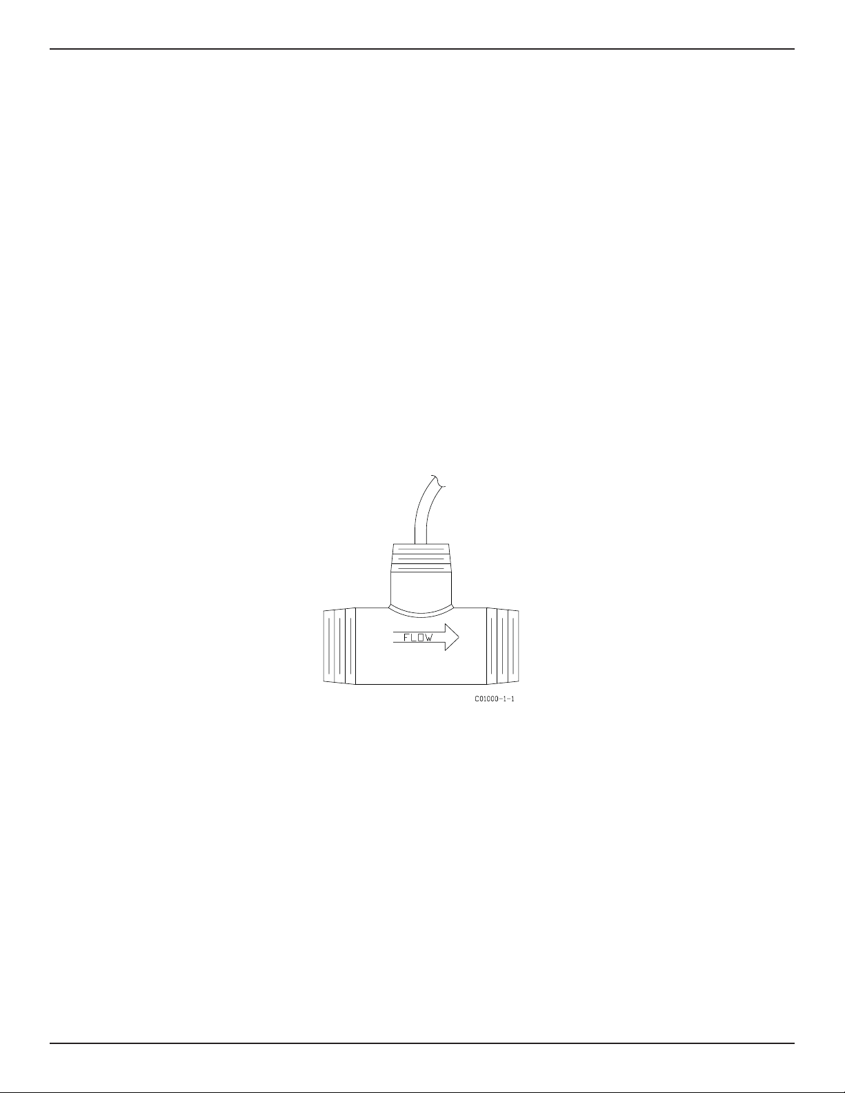
In-line NPT Assembly (FLT93-L)
The body length of the in-line assembly should be verifi ed to be sure the assembly will fi t into the process line. The direction of fl ow is important for proper operation. There is a fl ow direction arrow on the in-line pipe that is to point in the direction of fl ow. See Figure 2-3 for the
correct orientation.
If the instrument is a butt weld assembly, be sure to do the following: Remove the circuit board, properly ground the fl ow element before
welding, GTAW is highly recommended.
Figure 2-3 FLT93-L In-Line Flow Element
Fluid Components International LLC 13
Page 14
INSTALLATION FLT® Series FlexSwitch
Install and Wire the Enclosure(s)
TM
Caution:
In applications where the sensing element is located in an explosive environment, isolate the conduit before it leaves the
environment. A potting Y may be used to provide the isolation.
Pulling wires can cause damage to the control circuit. Therefore, remove the control circuit from the enclosure and use
extreme care when pulling wires into the enclosure.
Mount and wire the control circuit either locally or remotely (option) by following the local or remote enclosure procedure below.
Minimum Wire Size
Table 2-1 shows the smallest (maximum AWG number) copper wire that is used in the electrical cables. Use a lower gauge of wire for less of
a voltage drop. Contact FCI concerning greater distances than those listed in the table. The sensing element cable must be shielded. If the
cable is spliced the shield wire must be continued through the splice. If a terminal block is used, the shield must have its own terminal.
Enclosures Covers
All enclosure covers must be in place and securely closed to achieve environmental and safety classifi cations.
All circular thread-on covers should be tightened about 1/3-turn past hand tight.
Cover locks must be in place and secure if required by a particular approval.
Note: Nitrile (buna-N) O-rings are standard on the circular thread covers;n these O-rings have a 250°F (121°C) maximum useage
temperature.
A Viton O-ring [400°F (204°C) max. temp.] is available for the thread-on covers; these O-rings have a 500°F (260°C) maximum useage temperature.
To receive a Viton O-ring, provide FCI with the following information:
• Shipping address
• Quantity required
• Desired P/N:
Use P/N 000391-01 for the single conduit port enclosure (Local)
Cable and Conduit Entry Devices
The cable and conduit entry devices and blanking elements shall be of a certifi ed fl ameproof type EEx d, suitable for the conditions of use and
correctly installed. With the use of conduit entries a ceiling device shall be provided immediately on the entrance of the device.
All cable glands and conduit fi ttings, includign conduit plugs, must meet or exceed the area approval where the unit is being installed.
Maximum Distance for AWG
Connection
10 ft.
(3m)
50 ft
(15m)
100 ft.
(31m)
250 ft.
(76m)
500 ft.
(152m)
1000 ft.
(305m)
AC/DC Power 22 22 22 20 18 16
Relay (6A) 28 22 20 16 12 10
Flow Element Wires* 22 20 20 18 18 18
* Requires a shielded cable with the shield wire connected to the control socket only.
Table 2-1 Maximum AWG Number
14 Fluid Components International LLC
Page 15

FLT® Series FlexSwitchTM INSTALLATION
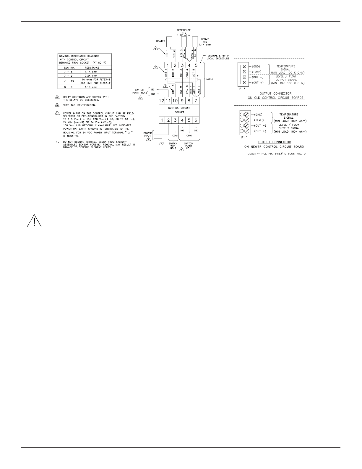
Wiring the Local Enclosure
This procedure is for instruments with the control circuit located in the sensing element enclosure.
1. Remove the control circuit from its socket. Do not remove the control circuit socket. Removal of the control circuit socket may cause
damage to the instrument.
2. Install conduit between the local enclosure and the power source and monitoring circuit. Provide watertight hardware and apply thread
sealant to all connections to prevent water damage.
Warning:
3. When connecting the relay wiring, do so with complete understanding of what the process requires of the instrument. The instrument
has dual SPDT or single DPDT relay output contacts dependent on the jumper confi guration for each alarm switch point. For the relay
logic, refer to Figure 2-5. Also refer to Table 3-5 and Table 3-6 in Chapter 3 - Operation. Relay contacts are shown with the relays deenergized. Wire in accordance with the system requirements.
Ensure that all power is off before wiring any circuit.
Figure 2-5 Local Wiring Diagram
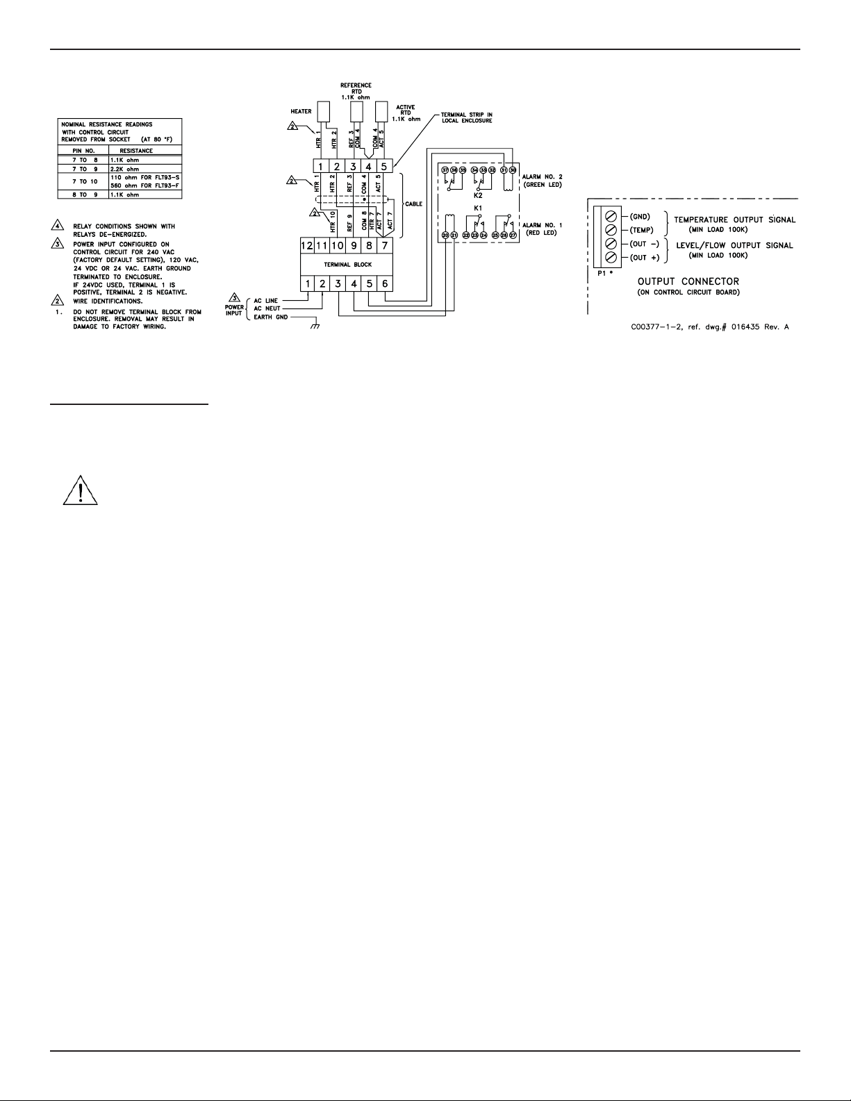
Wiring the Remote Enclosure
This procedure is for instruments with the control circuit located remotely from the sensing element.
Locate the Remote Hardware Location
Select a location for the remote enclosure within a 1000 feet (305 m) of the sensing element. Pigtail sensing elements can not be located
more than 10 feet (3 m) from the enclosure unless the pigtail is extended with the proper size cable listed in Table 2-1. If the cable is extended the cable connections should be located in a junction box with a 6 position terminal block. All 5 conductors and the shield must have
its own termination. The remote enclosure should be easily accessible with enough room to open the enclosure cabinet cover at any time.
Secure the remote enclosure solidly to a vertical surface capable of providing support. Use appropriate hardware to secure the enclosure.
1. Remove the control circuit from the remote enclosure.
2. Run a fi ve-conductor, shielded cable from the local enclosure to the remote enclosure. Use Table 2-1 to determine which wire gauge to
use.
3. Wire between the local and remote enclosures according to Figure 2-6.
Warning: Ensure that all power is off before wiring any circuit.
4. When connecting the relay wiring, do so with complete understanding of what the process requires of the instrument. The instrument
has dual SPDT or single DPDT relay output contacts dependent on the jumper confi guration for each alarm switch point. For the relay
logic, refer to Figure 2-6. Also refer to Table 3-5 and Table 3-6 in Chapter 3 - Operation. Relay contacts are shown with the relays deenergized. Wire in accordance with the system requirements.
Fluid Components International LLC 15
Page 16
INSTALLATION FLT® Series FlexSwitch
Figure 2-6 Remote Wiring Diagram
relay board is in the same enclosure as the control circuit. Both boards are mounted on the same panel and have been wired together at the
factory. This confi guration can be ordered without an enclosure which can be supplied by the customer.
The alarm connections are made at the auxiliary relay board where each alarm is driving a DPDT relay.
TM
Caution:
Do not connect any loads to the control circuit socket. Damage will occur to the control circuit if the alarm circuit is
energized.
Be sure the correct relay board has been ordered for the correct output. See the following paragraph.
This confi guration uses a control circuit that provides a switching voltage signal instead of relay contacts. The switch voltage is wired from
the control circuit socket to the auxiliary relay board actuating the relays.
The auxiliary relay board has several relay options that can be ordered. The options are as follows:
• Dry to 2 amps at 115 Vac or 28Vdc, Dry to 1 amp at 230 Vac (relay is enclosed in a plastic sealed cover).
• 100mA to 10mA at 115 Vac or 28Vdc, 50mA to 3 amps at 230 Vac (relay is enclosed in a plastic sealed cover).
• Dry to 0.5 amps at 115 Vac, hermetically sealed relay.
Make sure that the proper relays have been selected for the intended load. See Appendix A for the auxiliary relay board confi guration
drawing.
When connecting the relay wiring, do so with complete understanding of what the process requires of the instrument. The instrument has
dual DPDT or single 4PDT relay output contacts dependent on the jumper confi guration for each alarm switch point. For the relay logic, refer
to Figure 2-5. Also refer to Table 3-5 and Table 3-6 in Chapter 3 - Operation. Relay contacts are shown with the relays de-energized. Wire in
accordance with the system requirements.
The control circuit can be ordered with switching voltage outputs without ordering a relay board. This can be used with customer supplied
relays or any other device that has a differential input. The output voltage is 17 Vdc and will drive a load as low as 1500 ohms. Refer to
Figure 2-7 for the output terminals.
Wiring A Remote Control Circuit To An Auxiliary Relay Board
1. Run a four-conductor cable from the control circuit to the auxiliary relay board if the board was not factory installed. Use the wiring
diagram in Figure 2-7 to wire the boards together.
2. Attach the customer wiring as desired using Figure 2-7 as a wiring guide.
Wiring for this confi guration is the same as the sensing element wiring to the control circuit on a remote instrument.
16 Fluid Components International LLC
Page 17
FLT® Series FlexSwitchTM INSTALLATION
Figure 2-7 Auxilliary Relay Board Wiring Diagram
Wiring Output Signal Terminals
Two output signals are provided on the control circuit at P1. The signal voltage at positions 1 and 2 represents the process change. The
signal voltage at positions 3 and 4 is proportional to the temperature at the sensing element. See Figures 2-5 through 2-7. See also Chapter
3 for the physical layout of the control circuit.
Caution: Do not ground terminal 2 of P1. (Terminal 2 is the negative lead of the process signal.) This terminal is 9 volts above the
control circuit ground. The peripheral using this signal must have a differential input.
These voltages can be used by other peripherals with a minimum load of 100K ohms. The terminal block can be wired with between gauge
26 and 18 wire (22 gauge wire is normally used). The maximum recommended length of wire is 1000 feet. Shielding is required on any
length of cable. The shield must be terminated at position 4 on P1.
Early versions of the FLT93 require a connecting harness that was supplied with each instrument. The harness can be ordered if it is missing.
The FCI part number is 015664-01. Newer versions of the FLT93 require a supplied terminal plug.
Fluid Components International LLC 17
Page 18

INSTALLATION FLT® Series FlexSwitch
TM
INTENTIONALLY LEFT BLANK
18 Fluid Components International LLC
Page 19

FLT® Series FlexSwitchTM OPERATION
3 OPERATION
Caution: The control circuit contains electrostatic discharge (ESD) sensitive devices. Use standard ESD precautions when handling
the control circuit. See Chapter 2, Operation, for ESD details.
Factory Default Jumper Con guration
Unless a custom factory setup or calibration is specifi ed, the instrument is delivered in a standard factory confi guration. The standard default
jumper confi guration is shown in Table 3-1.
Input Power Factory Confi gured
Heater Power
Number of Alarms Two (J23). Each alarm has one set of SPDT contacts
Alarm No. 1 Red LED
Set Point Pot, R26
Alarm No. 2 Green LED
Set Point Pot, R25
FLT93-S 0.75 watts for air or liquid level applications. (J13)
FLT93-F 0.25 watts for air or liquid level applications. (J14)
Set to monitor fl ow or level signals (J20). Relay energized at fl ow or wet (J27)
Set to monitor temperature signals (J19). Relay energized below temperature (J25).
Set point at approximately:
250 F (121 C) for standard temperature,
500 F (260 C) for medium temperature,
850 F (454 C) for high temperature (FLT93-S Only)
Table 3-1 Standard Jumper Defaul Confi guration
If the order included custom factory setup and calibration, leave all settings alone. The instrument is ready for service without changes.
If custom factory setup or calibration was not ordered, confi gure the control circuit using the jumper tables (Tables 3-2 to 3-6) and then follow the set point adjustment section that is appropriate for the application.
Con guration Jumpers
If the order did not specify for the control circuit to be factory confi gured, the standard confi guration can be changed using Figure 3-1 and
Table 3-2 though Table 3-6. The factory default confi guration is shown as being underlined.
Heater Cut-Off
The 5298 control circuit has a heater cutoff switch that limits the skin temperature of the sensing element to a temperature differential of
approximately 150°F (66°C) above the process temperature. In the case where the instrument is used as a gas fl ow switch, and the heater
wattage is set too high, the temperature differential (DT) between the RTDs may exceed the usable input range of the control circuit. The usable input range can also be exceeded in the case where the instrument is used in liquid fl ow applications where the heater wattage is set at
the highest value, and when the sensing elements go dry. When the temperature differential is less than 150°F (66°C) the heater automatically turns back on. The yellow power indicator LED (DS3) turns on and off with the heater for a visual indication of the heater state. The
LED will alternate between on and off until the condition is corrected.
The reason for operating in the above extreme conditions is that the input signal range is at the widest point making the alarm set point
adjustment easier to perform. If the heater does cycle the operator may need to use the next lower wattage setting.
In some applications it is desirable to set the heater wattage high, even though the sensing element goes into the heater cutoff mode. An
example is when the instrument is used to detect the interface of two liquids. These liquids may have viscosities that will have signals very
close to each other. In order to have the maximum signal difference between the signals the heater wattage is set to its maximum. If the
sensing element detects a dry condition the control circuit will indicate a heater cutoff condition. The sensing element will not be dammaged
if it is left dry with the maximum heater wattage. The alarms can be set so one alarm will switch at the interface and one alarm can detect
when the element goes dry.
Fluid Components International LLC 19
Page 20

OPERATION FLT® Series FlexSwitch
TM
Figure 3-1 5298 Control Circuit Jumper Locations
Alarm Set Point Adjustments
Numerical Adjustment Versus Adjustment by Observation
An alarm set point is established using either numerical adjustment or adjustment by observation. The adjustment by observation requires
the customer to establish normal process operation and adjust the alarm set point relative to this condition. The numerical approach requires
measuring normal and alarm process conditions with a voltmeter and setting up the instrument in the calibrate mode based on these values.
The adjustment by observation requires less time to establish the alarm set point. The numerical adjustment requires control of the process
as well as additional time to establish the alarm set point. Use the adjustment procedure that is the most appropriate for the application
requirement.
Jumper
100-130 VAC 200-260VAC 18-26VAC 21-30VDC
J1 IN OUT OUT OUT
J2 OUT IN OUT OUT
J3 IN OUT OUT OUT
J4 OUT OUT IN OUT
J5 IN IN OUT OUT
Power Select - Factory Installed
J6 OUT IN IN IN
J7 OUT OUT OUT IN
J8 OUT OUT OUT IN
J9 OUT OUT IN OUT
Table 3-2 Input Power
20 Fluid Components International LLC
Page 21
FLT® Series FlexSwitchTM OPERATION
Jumper
FLT93-F ELEMENT WATTAGE
(560 OHM HTR)
FLT93-S ELEMENT WATTAGE
(110 OHM HTR)
Table 3-3A Selectable Heater Wattage Control
J13 is standard for FLT93-S and J14 is standard for FLT93-F
Jumper
FLT93-F ELEMENT WATTAGE
(560 OHM HTR)
FLT93-S ELEMENT WATTAGE
(110 OHM HTR)
Table 3-3B Fixed Heater Wattage Control
Jumper ALARM NO. 1
J27 RELAY DE-ENERGIZED WITH LOW FLOW, LOW LEVEL
(DRY) OR HIGH TEMPERATURE.
J26 RELAY DE-ENERGIZED WITH HIGH FLOW, HIGH LEVEL
(WET) OR LOW TEMPERATURE.
Jumper ALARM NO. 2
J13 J14 J33
N.A.
0.75
WATTS
J32 J12 J13 J14 J33
0.57
WATTS
3
WATTS
0.20
WATTS
N.A. OFF
0.52
WATTS
1.75
WATTS
OFF
0.49
WATTS
0.75
WATTS
ALARM NO. 1 J20 J21
ALARM NO. 2
J23 DUAL SPDT (ONE RELAY PER ALARM)
J22 SINGLE DPDT (DISABLES ALARM NO. 2)
Table 3-6 Relay Contact Confi guration
0.20
WATTS
0.27
WATTS
FLOW/LEVEL TEMP
Table 3-4 Application
OFF
OFF
J18 J19
J25 RELAY DE-ENERGIZED WITH LOW FLOW, LOW LEVEL
(DRY) OR HIGH TEMPERATURE.
J24 RELAY DE-ENERGIZED WITH HIGH FLOW, HIGH LEVEL
(WET) OR LOW TEMPERATURE.
Table 3-5 Relay Energization
Fluid Components International LLC 21
Page 22

OPERATION FLT® Series FlexSwitch
Numerical Alarm Set Point Adjustment
The control circuit has two mutually exclusive alarms; they are identifi ed as Alarm No. 1 and Alarm No. 2. Each has an alarm set point adjustment potentiometer and LED indicator. Both alarms can be setup for one of three applications; fl ow, level/interface, or temperature. The
following application specifi c adjustment procedures are generic and can be used for setting either or both alarms. Use Figure 3-2 to help
locate the important setup components (potentiometers, LEDs, etc.)
TM
Figure 3-2 5298 Control Circuit Component Locations
Air/Gas Flow Applications
1. Remove the instrument’s enclosure cover.
2. Ensure the confi guration jumpers on the control circuit are correct for this application. See Tables 3-3 through 3-6.
3. Check to make sure the input power jumpers match the power to be applied to the instrument. See Table 3-2.
4. Apply power to the instrument. Verify the yellow LED is on and allow the instrument fi fteen minutes to warm-up.
5. Verify the mode switch is in the RUN position.
6. Attach a DC voltmeter to the P1 terminal block with the positive (+) lead to position one and the negative (-) lead to position two.
Note: The terminal block can be unplugged from the control circuit to facilitate easy connections.
7. Establish the normal process fl ow condition and allow the signal to stabilize.
Note: The output signal at connector P1 will vary inversely with changes in the process fl ow rate. The output signal level is relative to
the type of process media being measured and the heater wattage setting. See Figure 3-3.
8. Record the normal fl ow signal value.
Normal Flow Signal = ________ volts DC
9. Follow either the Detecting Decreasing Flow or the Detecting Increasing Flow procedure for each fl ow application alarm.
22 Fluid Components International LLC
Page 23

FLT® Series FlexSwitchTM OPERATION
AIR OR GAS
Potentiometer
(POT)
OIL
WATER
OUTPUT VOLTAGE
0
FLOW
ABOVE SETPOINT
LED OFF
BELOW SETPOINT
Figure 3-3 Flow Application Signal Output
Detecting Decreasing Flow (low fl ow alarm)
1. Stop the process fl ow and allow the signal to stabilize.
2. Record the no-fl ow signal. (The no-fl ow signal should be greater than the normal fl ow signal.)
FIELD ADJUSTABLE
SET POINT
R25 AND R26
Adjust
Clockwise,
Turns
LED ON
LED ON
SET POINT
Adjust
Counter-
clockwise,
Turns
LED OFF
C00204-1-2
No-Flow Signal = ________ volts DC
3. Determine the set point by calculating the average of the normal and no-fl ow output signals. (i.e.; If the normal signal is 2.000 volts and
the no-fl ow signal is 5.000 volts, then the calculated set point would be 3.500 volts.)
4. Record this value.
Calculated Set Point = ________ volts DC
Note: The calculated set point must be at least 0.020 volts greater than the normal signal to ensure that the alarm will reset.
5. Slide the mode switch to the CALIBRATE position.
6. Adjust the calibrate potentiometer (R24) until the voltmeter equals the calculated set point.
7. For the appropriate alarm, determine whether the status LED is on or off (red for No. 1 or green for No. 2).
If the LED is off, turn the set point adjustment potentiometer (R26 for alarm No. 1 or R25 for alarm No.2) slowly clockwise just until the
LED turns on.
OR
If the LED is on, turn the set point adjustment potentiometer (R26 for alarm No. 1 or R25 for alarm No. 2) counterclockwise until the LED
turns off and then slowly clockwise just until the LED turns on.
8. If this is the only fl ow application alarm to be setup, then skip to the Continue With the Air/Gas Flow Procedure.
Detecting Increasing Flow (high fl ow alarm)
1. Establish the excessive process fl ow condition and allow the signal to stabilize.
2. Record the high fl ow signal. (The high fl ow signal should be less than the normal fl ow signal.)
High Flow Signal = ________ volts DC
3. Determine the set point by calculating the average of the normal and high fl ow output signals. (i.e., If the normal signal is 2.000 volts
and the high fl ow signal is 1.000 volts, then the calculated set point would be 1.500 volts.)
Fluid Components International LLC 23
Page 24

OPERATION FLT® Series FlexSwitch
4. Record this value.
Calculated Set Point = ________ volts DC
Note: The calculated set point must be at least 0.020 volts less than the normal signal to ensure that the alarm will reset.
5. Slide the mode switch to the CALIBRATE position.
6. Adjust the calibrate potentiometer (R24) until the voltmeter equals the calculated set point.
7. For the appropriate alarm, determine whether the status LED is on or off (red for No. 1 or green for No. 2).
If the LED is on, turn the set point adjustment potentiometer ( R26 for alarm No. 1 or R25 for alarm No. 2) slowly counterclockwise just
until the LED turns off.
OR
If the LED is off, turn the set point adjustment potentiometer ( R26 for alarm No. 1 or R25 for alarm No. 2) clockwise until the LED turns
on and then slowly counterclockwise just until the LED turns off.
Continue With the Air/Gas Flow Procedure
1. Slide the mode switch to the RUN position.
2. Establish the normal process fl ow condition. For low-fl ow alarm setups, the status LED should be off. For high fl ow alarm setups, the
status LED should be on.
3. Establish the process alarm condition and monitor the voltmeter display.
4. When the output signal passes through the calculated set point value, the status LED should turn on for low-fl ow alarms, off for high
fl ow alarms, and the relay contacts should change state.
5. Reestablish the normal process fl ow condition. Both the LED and the relay contacts should reset.
6. Disconnect the voltmeter from P1.
7. Replace the enclosure cover.
TM
Note: The alarm can be set for a specifi c fl ow rate. Follow the Air/Gas Flow Application procedure up to step 7 except establish the
specifi c fl ow rate rather than the normal fl ow. The output signal will be the set point value. Determine whether the alarm
should actuate with decreasing or increasing fl ow and skip to the appropriate step 4 in Detecting Decreasing Flow or Detecting Increasing Flow, respectfully. Enter the specifi c fl ow rate value as the set point. Then follow the Continue With the Air /
Gas Flow Procedure steps.
The relay logic default confi guration is set for the relay coil to be de-energized when the fl ow signal voltage is greater than
the set point value. (i.e., Assume that the normal process fl ow condition has been established. In this state, the relay coil
will be energized if the alarm has been set for low-fl ow detection and de-energized if the alarm has been set for high fl ow
detection.) A recommendation is to have the relay coils energized when the process condition is normal. This will enable the
alarm to close or open the contacts in case of a power failure.
Wet/Dry Liquid Level Applications
1. Remove the instrument’s enclosure cover.
2. Ensure the confi guration jumpers on the control circuit are correct for this application. See Tables 3-3 through 3-6.
3. Check to make sure the input power jumpers match the power to be applied to the instrument. See Table 3-2.
4. Apply power to the instrument. Verify the yellow LED is on and allow the instrument fi fteen minutes to warm-up.
5. Verify the mode switch is in the RUN position.
6. Attach a DC voltmeter to P1 with the positive (+) lead to position one and the negative (-) lead to position two.
Note: The terminal block can be unplugged from the control circuit to facilitate easy connections.
24 Fluid Components International LLC
Page 25

FLT® Series FlexSwitchTM OPERATION
7. Raise the process fl uid level so the sensing element is wet.
8. Allow the output signal to stabilize and record the wet condition value.
Wet Condition Signal = ________ volts DC
Note: The output signal at P1 is relative to the type of process media detected. See Figure 3-4.
9. Lower the process fl uid level so the sensing element is dry.
10. Allow the output signal to stabilize and record the dry condition value. (The dry signal should be greater than the wet signal.)
Dry Condition Signal = ________ volts DC
11. Determine the set point by calculating the average of the wet and dry output signals. (i.e., If the wet signal is 0.200 volts and the dry
signal is 4.000 volts, then the calculated set point would be 2.100 volts.)
12. Record this value.
Calculated Set Point = ________ volts DC
Note: The calculated set point must be at least 0.015 volts greater than the wet signal and 0.020 volts less than the dry signal to
ensure that the alarm will reset.
FIELD ADJUSTABLE
SET POINT
AIR OR GAS
OIL
OUTPUT VOLTAGE
Potentiometer
(POT)
A
I
R
T
O
W
A
T
E
R
DIESEL
WATER
R25 AND R26
Adjust
R
I
A
O
T
R
E
T
A
W
LED ON
ABOVE SETPOINT
LED OFF
BELOW SETPOINT
Clockwise,
Turns
LED ON
SET POINT
Adjust
Counter-
clockwise,
Turns
LED OFF
0
TIME
C00070-1-2
Figure 3-4 Level Application Signal Output
13. Slide the mode switch to the CALIBRATE position.
14. Adjust the calibrate potentiometer (R24) until the voltmeter equals the calculated set point.
15. For the appropriate alarm, determine whether the status LED is on or off (red for No. 1 or green for No. 2).
16. Follow either the Detecting Dry Condition or the Detecting Wet Condition for each level application alarm.
Detecting Dry Condition (low level alarm)
If the status LED is off, turn the set point adjustment potentiometer (R26 for alarm No. 1 or R25 for alarm No. 2) slowly clockwise just
until the LED turns on.
OR
If the status LED is on, turn the set point adjustment potentiometer (R26 for alarm No. 1 or R25 for alarm No. 2) counterclockwise until
the LED turns off and then slowly clockwise just until the LED turns on.
Fluid Components International LLC 25
Page 26

OPERATION FLT® Series FlexSwitch
Detecting Wet Condition (high level alarm)
If the status LED is on, turn the set point adjustment potentiometer (R26 for alarm No. 1 or R25 for alarm No. 2) slowly counterclockwise
just until the LED turns off.
OR
If the status LED is off, turn the set point adjustment potentiometer (R26 for alarm No. 1 or R25 for alarm No. 2) clockwise until the LED
turns on and then slowly counterclockwise just until the LED turns off.
17. Slide the mode switch to the RUN position. The status LED should be on if the sensing element is dry and off if the sensing element is
wet.
18. Monitor the voltmeter display while raising or lowering the process fl uid level. When the output signal passes through the set point, the
status LED should change states and the relay contacts should change state.
19. Reestablish the normal level condition. Both the LED and relay contacts should reset.
20. Disconnect the voltmeter from P1.
21. Replace the enclosure cover.
Note: The relay logic default confi guration is set for the relay coil to be de-energized when the level signal is greater than the set
point value. (i.e., The relay coil will be de-energized when the sensing element is dry.) A recommendation is to have the
relay coils energized when the process condition is normal. This will enable the alarm to close or open the contacts in case
of a power failure.
TM
Liquid Flow Applications
1. Remove the instrument’s enclosure cover.
2. Check to make sure the input power jumpers match the power to be applied to the instrument. See Table 3-2.
3. As necessary, set the following control circuit confi guration jumpers. See Tables 3-3 through 3-6.
Application: J20 or J18 (Flow/Level) for alarm No. 1 or No. 2, respectively.
Heater Power: J32 (3 watts for FLT93-S or 0.57 watts for FLT93-F).
4. Apply power to the instrument. Verify the yellow LED is on. Allow the instrument fi fteen minutes to warm-up.
5. Verify the mode switch is in the RUN position.
6. Attach a DC voltmeter to P1 connector with the positive (+) lead to position one and the negative (-) lead to position two.
Note: The terminal block can be unplugged from the control circuit to facilitate easy connections.
The output signal at connector P1 will vary inversely with changes in the process fl ow rate. The output signal level is also
relative to the type of process media being measured. See Figure 3-3.
7. Establish the normal process fl ow condition and allow the signal to stabilize.
8. Record the normal fl ow signal value.
Normal Flow Signal = ________ volts DC
9. Follow either the Detecting Decreasing Flow or Detecting Increasing Flow procedure for each Liquid fl ow application alarm.
Detecting Decreasing Flow (low fl ow alarm)
1. Stop the process fl ow and allow the signal to stabilize.
2. Record the no-fl ow signal. (The no-fl ow signal should be greater than the normal fl ow signal.)
No-Flow Signal = ________ volts DC
3. Determine the set point by calculating the average of the normal and no-fl ow output signals. (i.e.; If the normal signal is 0.080 volts and
the no-fl ow signal is 0.300 volts, then the calculated set point would be 0.190 volts.)
4. Record this value.
Calculated Set Point = ________ volts DC
26 Fluid Components International LLC
Page 27

FLT® Series FlexSwitchTM OPERATION
Note: The calculated set point must be at least 0.020 volts greater than the normal signal to ensure that the alarm will reset.
5. Slide the mode switch to the CALIBRATE position.
6. Adjust the calibrate potentiometer (R24) until the voltmeter equals the calculated set point.
7. For the appropriate alarm, determine whether the status LED is on or off (red for No. 1 or green for No. 2).
If the LED is off, turn the set point adjustment potentiometer (R26 for alarm No. 1 or R25 for alarm No. 2) slowly clockwise just until the
LED turns on.
OR
If the LED is on, turn the set point adjustment potentiometer (R26 for alarm No. 1 or R25 for alarm No. 2) counterclockwise until the LED
turns off and then slowly clockwise just until the LED turns on.
8. If this is the only fl ow application alarm to be setup, then skip to Continue With the Liquid Flow Applications procedure.
Detecting Increasing Flow Rate (high fl ow alarm)
1. Establish the excessive fl ow condition and allow the signal to stabilize.
2. Record the high fl ow signal. (The high fl ow signal should be less than the normal fl ow signal.)
High Flow Signal = ________ volts DC
3. Determine the set point by calculating the average of the normal and high fl ow output signals. (i.e.; If the normal signal is 0.080 volts
and the high fl ow signal is 0.030 volts, then the calculated set point would be 0.055 volts.)
4. Record this value.
Calculated Set Point = ________ volts DC
Note: The calculated set point must be at least 0.020 volts less than the normal signal to ensure that the alarm will reset.
5. Slide the mode switch to the CALIBRATE position.
6. Adjust the calibrate potentiometer (R24) until the voltmeter equals the calculated set point.
7. For the appropriate alarm, determine whether the status LED is on or off (red for No. 1 or green for No. 2).
8. If the LED is on, turn the set point adjustment potentiometer (R26 for alarm No. 1 or R25 for alarm No. 2) slowly counterclockwise just
until the LED turns off.
OR
If the LED is off, turn the set point adjustment potentiometer (R26 for alarm No. 1 or R25 for alarm No. 2) clockwise until the LED turns on
and then slowly counterclockwise just until the LED turns off.
Continue With the Liquid Flow Applications
1. Slide the mode switch to the RUN position.
2. Establish the normal process fl ow condition. For low-fl ow alarm setups, the status LED should be off. For high fl ow alarm setups, the
status LED should be on.
3. Establish the process alarm condition and monitor the voltmeter display.
When the output signal passes through the calculated set point value, the status LED should turn on for low-fl ow alarms, off for high
fl ow alarms, and the relay contacts should change state.
4. Reestablish the normal process fl ow condition. Both the LED and the relay contacts should reset.
5. Disconnect the voltmeter from P1.
6. Replace the enclosure cover.
Fluid Components International LLC 27
Page 28

OPERATION FLT® Series FlexSwitch
Note: The alarm can be set for a specifi c fl ow rate. Follow the Air/Gas Flow Application procedure up to step 7 except establish the
specifi c fl ow rate rather than the normal fl ow. The output signal will be the set point value. Determine whether the alarm
should actuate with decreasing or increasing fl ow and skip to the appropriate step 4 in Detecting Decreasing Flow or Detecting Increasing Flow, respectfully. Enter the specifi c fl ow rate value as the set point. Then follow the Continue With the Air /
Gas Flow Procedure steps.
The relay logic default confi guration is set for the relay coil to be de-energized when the fl ow signal voltage is greater than
the set point value. (i.e., Assume that the normal process fl ow condition has been established. In this state, the relay coil
will be energized if the alarm has been set for low-fl ow detection and de-energized if the alarm has been set for high fl ow
detection.) A recommendation is to have the relay coils energized when the process condition is normal. This will enable the
alarm to close or open the contacts in case of a power failure.
Adjustment by Observation
Note: The control circuit has two mutually exclusive alarms; they are identifi ed as Alarm No. 1 and Alarm No. 2 and each has a set
point adjustment potentiometer and LED indicator. Each alarm can be setup for one of three applications: fl ow, level/interface, or temperature. The following application specifi c adjustment procedures are generic and can be used for setting either
or both alarms. The mode switch must be in the RUN position. Use Figure 3-2 to help locate the adjustment potentiometers
and LEDs.
Flow Applications
1. Ensure that the instrument has been properly installed in the pipeline. Fill the pipeline so the sensing element is surrounded by the
process medium.
2. Apply power to the instrument and allow fi fteen minutes for the sensing element to become active and stabilize.
3. Flow the pipeline at the normal or expected rate. Remove the enclosure cover to allow access to the control circuit to make adjustments.
TM
Detecting Decreasing Flow (low fl ow alarm)
If the status LED is off, turn the set point adjustment potentiometer clockwise until the LED turns on. With the LED on, slowly turn the potentiometer counterclockwise one turn past the point at which the LED just turns off. The potentiometer may have up to one-quarter turn of
hysteresis, therefore, if the mark is overshot, the procedure should be repeated.
Detecting Increasing Flow (high fl ow alarm)
If the status LED is on, turn the set point adjustment potentiometer counterclockwise until the LED turns off. With the LED off, slowly turn the
potentiometer clockwise one-half turn past the point at which the LED just turns on. The potentiometer may have up to one-quarter turn of
hysteresis, therefore, if the mark is overshot, the procedure should be repeated.
Signal Output for Flow Applications
The output signal at connector P1 varies inversely with fl ow rate. The output signal level is also relative to the type of process media, see
Figure 3-3.
Level Applications
1. Ensure that the instrument has been properly installed in the vessel.
2. Apply power to the instrument and allow fi fteen minutes for the sensing element to become active and stabilize.
3. Remove the enclosure cover to allow access to the control circuit to make adjustments.
Detecting Dry Condition (adjustment with sensing element wet)
Verify that the sensing element is wet. If the status LED is off, turn the set point adjustment potentiometer clockwise until the LED turns on.
With the LED on, slowly turn the potentiometer counterclockwise one turn past the point at which the LED just turns off. The potentiometer
may have up to one-quarter turn of hystereses, therefore, if the mark is overshot, the procedure should be repeated.
28 Fluid Components International LLC
Page 29

FLT® Series FlexSwitchTM OPERATION
Detecting Wet Condition (adjustment with sensing element dry)
Caution: Give consideration to the fact that air or gas fl owing over the sensing element may decrease the output signal resulting in
a false alarm. If the sensing element is exposed to air or gas fl ow in the dry condition, or where the process media is highly
viscous, make set point adjustments in the wet condition only.
Field adjustments made in the dry condition should be performed in the actual service environment or within a condition that approximates
that environment. Provision should be made for the worst case condition of air or gas fl ow on the sensing element. If the status LED is on,
turn the set point adjustment potentiometer counterclockwise until the LED turns off. (If the LED cannot be turned off, the instrument must be
set in the wet condition.)
With the LED off, slowly turn the potentiometer clockwise 1 turn past the point at which the LED just goes on. The potentiometer may have
up to one-quarter turn of hysteresis, therefore, if the mark is overshot, the procedure should be repeated.
Signal Output for Level Applications
The output signal at P1 is lowest in water and highest in air. See Figure 3-4.
Temperature Applications
For temperature versus voltage values, see Table 3-7 located at the rear of this chapter. These values have an accuracy of ±5°F (2.78°C).
There is also a conversion formula later in this chapter to convert the temperature output voltage to degrees fahrenheit. If a factory calibration chart was ordered look for it in the plastic page protector at the back of this manual. Make sure the serial number of the chart matches
the instrument to be adjusted.
Note: It is reccommended not to use the instrument for a dual fl ow and temperature application in air or gas unless the fl ow rate is
greater than 1.0 SFPS. (The instrument may be used for a dual fl ow and temperature application in liquids at any fl ow rate.)
When using the instrument for dual level and temperature applications, the temperature signal can be as much as 50°F
(28°C) high when the sensing element is in still air.
Turn the heater off for temperature only applications. To turn off the heater remove the heater control jumper from the
heater, control header. The jumper may be stored on the control circuit by plugging it across J12 and J14. Placing the jumper
here will not turn on the heater.
1. Remove the instrument’s enclosure cover.
2. Ensure the confi guration jumpers on the control circuit are correct for this application. See Tables 3-3 through 3-6.
3. Check to make sure the input power jumpers match the power to be applied to the instrument. See Table 3-2.
4. Apply power to the instrument. Verify the yellow LED is on. Allow the instrument fi fteen minutes to warm-up.
5. Verify the mode switch is in the RUN position.
6. Attach a DC voltmeter to P1 with the positive (+) lead to position 3 and the negative (-) lead to position 4.
Note: The terminal block can be unplugged from the control circuit to facilitate easy connections.
7. Establish the normal process temperature condition and allow the signal to stabilize.
8. Record the normal temperature signal value.
Normal Temperature Signal = ________ volts DC
Note: The output signal at connector P1 will vary proportionally with the process temperature.
9. Follow either the Detecting Increasing Temperature or the Detecting Decreasing Temperature procedure for each temperature application
alarm.
Fluid Components International LLC 29
Page 30

OPERATION FLT® Series FlexSwitch
Detecting Increasing Temperature (high temperature alarm)
1. Slide the mode switch to the CALIBRATE position.
2. Adjust the calibrate potentiometer (R24) until the voltmeter equals the desired temperature signal in Table 3-7.
3. For the appropriate alarm, determine whether the status LED is on or off (red for No. 1 or green for No. 2).
If the LED is off, turn the set point adjustment potentiometer (R26 for alarm No. 1 or R25 for alarm No. 2) slowly clockwise just until the
LED turns on.
OR
If the LED is on, turn the set point adjustment potentiometer (R26 for alarm No. 1 or R25 for alarm No. 2) counterclockwise until the LED
turns off and then slowly clockwise just until the LED turns on.
If this is the only temperature application alarm to be setup, then skip to the Continue With the Temperature Application procedure.
Detecting Decreasing Temperature (low temperature alarm)
1. Slide the mode switch to the CALIBRATE position.
2. Adjust the calibrate potentiometer (R24) until the voltmeter equals the normal temperature signal.
3. For the appropriate alarm, determine whether the status LED is on or off (red for No. 1 or green for No. 2).
If the LED is on, turn the set point adjustment potentiometer (R26 for alarm No. 1 or R25 for alarm No. 2) slowly counterclockwise just
until the LED turns off.
OR
If the LED is off, turn the set point adjustment potentiometer (R26 for alarm No. 1 or R25 for alarm No. 2) clockwise until the LED turns on
and then slowly counterclockwise just until the LED turns off.
TM
Continue With the Temperature Applications
1. Slide the mode switch to the RUN position.
2. Establish the normal process temperature condition. For the high temperature alarm setups, the status LED should be off at normal
temperatures. For the low temperature alarm setups, the status LED should be on at normal temperatures.
3. Establish the process alarm condition and monitor the voltmeter display.
4. When the output signal passes through the set point value, the status LED should turn on for high temperature alarms, off for low temperature alarms, and the relay contacts should change state.
5. Reestablish the normal process temperature condition. The LED and relay contacts should reset.
6. Disconnect the voltmeter from P1.
7. Replace the enclosure cover.
Note: The relay default confi guration is for the relay coil to be de-energized when the temperature signal is greater than the set
point value. (i.e., Assume that the normal process temperature condition has been established. In this state, the relay coil
will be energized.)
30 Fluid Components International LLC
Page 31

FLT® Series FlexSwitchTM OPERATION
Converting Temp Out Voltage to Temperature in Degrees F or Degrees C
This formula is useful when monitoring the temperature output voltage with a data acquisition system where the formula can be used in the
program.
Use the following formula to determine what the temperature is in degrees Fahrenheit, if the FLT temperature output voltage is known.
y = a + b(x / .0002) + c(x / 0.002)
2
Where: y = Temperature in Degrees F
x = FLT Temperature Output Voltage
a = -409.3253
b = 0.42224
c = .00001904
Use the following equation to convert the temperature from degrees Fahrenheit to Celsius:
C = (F - 32) x 5/9
Fluid Components International LLC 31
Page 32

OPERATION FLT® Series FlexSwitch
TM
0.00385 OHMS/OHMS/ºC 1000 OHM PLATINUM SENSORS
TEMPERATURE VERSUS VOLTAGE OUTPUT, FLT93
Temp Output
Voltage
°F °C Temp Output
Voltage
°F °C Temp Output
Voltage
°F °C Temp Output
Voltage
°F °C
1.400 -104 -76 1.600 -59 -51 1.800 -14 -25 2.000 32 0
1.405 -103 -75 1.605 -58 -50 1.805 -13 -25 2.005 33 1
1.410 -102 -75 1.610 -57 -49 1.810 -12 -24 2.010 34 1
1.415 -101 -74 1.615 -56 -49 1.815 -10 -24 2.015 35 2
1.420 -100 -73 1.620 -55 -48 1.820 -9 -23 2.020 37 3
1.425 -99 -73 1.625 -54 -48 1.825 -8 -22 2.025 38 3
1.430 -98 -72 1.630 -53 -47 1.830 -7 -22 2.030 39 4
1.435 -97 -71 1.635 -51 -46 1.835 -6 -21 2.035 40 4
1.440 -95 -71 1.640 -50 -46 1.840 -5 -20 2.040 41 5
1.445 -94 -70 1.645 -49 -45 1.845 -4 -20 2.045 42 6
1.450 -93 -70 1.650 -48 -44 1.850 -2 -19 2.050 43 6
1.455 -92 -69 1.655 -47 -44 1.855 -1 -19 2.055 45 7
1.460 -91 -68 1.660 -46 -43 1.860 0 -18 2.060 46 8
1.465 -90 -68 1.665 -45 -43 1.865 1 -17 2.065 47 8
1.470 -89 -67 1.670 -43 -42 1.870 2 -17 2.070 48 9
1.475 -88 -66 1.675 -42 -41 1.875 3 -16 2.075 49 10
1.480 -86 -66 1.680 -41 -41 1.880 4 -15 2.080 50 10
1.485 -85 -65 1.685 -40 -40 1.885 6 -15 2.085 52 11
1.490 -84 -65 1.690 -39 -39 1.890 7 -14 2.090 53 12
1.495 -83 -64 1.695 -38 -39 1.895 8 -13 2.095 54 12
1.500 -82 -63 1.700 -37 -38 1.900 9 -13 2.100 55 13
1.505 -81 -63 1.705 -36 -38 1.905 10 -12 2.105 56 13
1.510 -80 -62 1.710 -34 -37 1.910 11 -12 2.110 57 14
1.515 -79 -61 1.715 -33 -36 1.915 12 -11 2.115 58 15
1.520 -77 -61 1.720 -32 -36 1.920 14 -10 2.120 60 15
1.525 -76 -60 1.725 -31 -35 1.925 15 -10 2.125 61 16
1.530 -75 -60 1.730 -30 -34 1.930 16 -9 2.130 62 17
1.535 -74 -59 1.735 -29 -34 1.935 17 -8 2.135 63 17
1.540 -73 -58 1.740 -28 -33 1.940 18 -8 2.140 64 18
1.545 -72 -58 1.745 -26 -32 1.945 19 -7 2.145 65 19
1.550 -71 -57 1.750 -25 -32 1.950 20 -6 2.150 67 19
1.555 -70 -56 1.755 -24 -31 1.955 22 -6 2.155 68 20
1.560 -68 -56 1.760 -23 -31 1.960 23 -5 2.160 69 20
1.565 -67 -55 1.765 -22 -30 1.965 24 -5 2.165 70 21
1.570 -66 -55 1.770 -21 -29 1.970 25 -4 2.170 71 22
1.575 -65 -54 1.775 -20 -29 1.975 26 -3 2.175 72 22
1.580 -64 -53 1.780 -18 -28 1.980 27 -3 2.180 74 23
1.585 -63 -53 1.785 -17 -27 1.985 28 -2 2.185 75 24
1.590 -62 -52 1.790 -16 -27 1.990 30 -1 2.190 76 24
1.595 -60 -51 1.795 -15 -26 1.995 31 -1 2.195 77 25
Table 3-7. Temperature versus Voltage Output - Page 1
32 Fluid Components International LLC
Page 33

FLT® Series FlexSwitchTM OPERATION
0.00385 OHMS/OHMS/ºC 1000 OHM PLATINUM SENSORS
TEMPERATURE VERSUS VOLTAGE OUTPUT, FLT93
Temp Output
Voltage
2.200 78 26 2.400 125 52 2.600 172 78 2.800 219 104
2.205 79 26 2.405 126 52 2.605 173 78 2.805 220 105
2.210 80 27 2.410 127 53 2.610 174 79 2.810 221 105
2.215 82 28 2.415 128 53 2.615 175 80 2.815 223 106
2.220 83 28 2.420 129 54 2.620 176 80 2.820 224 107
2.225 84 29 2.425 131 55 2.625 178 81 2.825 225 107
2.230 85 30 2.430 132 55 2.630 179 82 2.830 226 108
2.235 86 30 2.435 133 56 2.635 180 82 2.835 227 109
2.240 87 31 2.440 134 57 2.640 181 83 2.840 229 109
2.245 89 31 2.445 135 57 2.645 182 84 2.845 230 110
2.250 90 32 2.450 136 58 2.650 184 84 2.850 231 111
2.255 91 33 2.455 138 59 2.655 185 85 2.855 232 111
2.260 92 33 2.460 139 59 2.660 186 86 2.860 233 112
2.265 93 34 2.465 140 60 2.665 187 86 2.865 235 113
2.270 94 35 2.470 141 61 2.670 188 87 2.870 236 113
2.275 96 35 2.475 142 61 2.675 189 87 2.875 237 114
2.280 97 36 2.480 144 62 2.680 191 88 2.880 238 115
2.285 98 37 2.485 145 63 2.685 192 89 2.885 239 115
2.290 99 37 2.490 146 63 2.690 193 89 2.890 241 116
2.295 100 38 2.495 147 64 2.695 194 90 2.895 242 117
2.300 101 39 2.500 148 65 2.700 195 91 2.900 243 117
2.305 103 39 2.505 149 65 2.705 197 91 2.905 244 118
2.310 104 40 2.510 151 66 2.710 198 92 2.910 245 119
2.315 105 41 2.515 152 67 2.715 199 93 2.915 247 119
2.320 106 41 2.520 153 67 2.720 200 93 2.920 248 120
2.325 107 42 2.525 154 68 2.725 201 94 2.925 249 121
2.330 108 42 2.530 155 68 2.730 202 95 2.930 250 121
2.335 110 43 2.535 156 69 2.735 204 95 2.935 251 122
2.340 111 44 2.540 158 70 2.740 205 96 2.940 253 123
2.345 112 44 2.545 159 70 2.745 206 97 2.945 254 123
2.350 113 45 2.550 160 71 2.750 207 97 2.950 255 124
2.355 114 46 2.555 161 72 2.755 208 98 2.955 256 124
2.360 115 46 2.560 162 72 2.760 210 99 2.960 257 125
2.365 117 47 2.565 164 73 2.765 211 99 2.965 258 126
2.370 118 48 2.570 165 74 2.770 212 100 2.970 260 126
2.375 119 48 2.575 166 74 2.775 213 101 2.975 261 127
2.380 120 49 2.580 167 75 2.780 214 101 2.980 262 128
2.385 121 50 2.585 168 76 2.785 216 102 2.985 263 128
2.390 122 50 2.590 169 76 2.790 217 103 2.990 264 129
2.395 124 51 2.595 171 77 2.795 218 103 2.995 266 130
°F °C Temp Output
Voltage
°F °C Temp Output
Voltage
°F °C Temp Output
Voltage
°F °C
Table 3-7. Temperature versus Voltage Output - Page 2
Fluid Components International LLC 33
Page 34

OPERATION FLT® Series FlexSwitch
TM
0.00385 OHMS/OHMS/ºC 1000 OHM PLATINUM SENSORS
TEMPERATURE VERSUS VOLTAGE OUTPUT, FLT93
Temp Output
Voltage
°F °C Temp Output
Voltage
°F °C Temp Output
Voltage
°F °C Temp Output
Voltage
°F °C
3.000 267 130 3.200 315 157 3.400 363 184 3.600 412 211
3.005 268 131 3.205 316 158 3.405 365 185 3.605 414 212
3.010 269 132 3.210 317 159 3.410 366 186 3.610 415 213
3.015 270 132 3.215 319 159 3.415 367 186 3.615 416 213
3.020 272 133 3.220 320 160 3.420 368 187 3.620 417 214
3.025 273 134 3.225 321 161 3.425 370 188 3.625 419 215
3.030 274 134 3.230 322 161 3.430 371 188 3.630 420 215
3.035 275 135 3.235 323 162 3.435 372 189 3.635 421 216
3.040 276 136 3.240 325 163 3.440 373 190 3.640 422 217
3.045 278 136 3.245 326 163 3.445 374 190 3.645 423 217
3.050 279 137 3.250 327 164 3.450 376 191 3.650 425 218
3.055 280 138 3.255 328 165 3.455 377 192 3.655 426 219
3.060 281 138 3.260 330 165 3.460 378 192 3.660 427 220
3.065 282 139 3.265 331 166 3.465 379 193 3.665 428 220
3.070 284 140 3.270 332 167 3.470 381 194 3.670 430 221
3.075 285 140 3.275 333 167 3.475 382 194 3.675 431 222
3.080 286 141 3.280 334 168 3.480 383 195 3.680 432 222
3.085 287 142 3.285 336 169 3.485 384 196 3.685 433 223
3.090 288 142 3.290 337 169 3.490 385 196 3.690 435 224
3.095 290 143 3.295 338 170 3.495 387 197 3.695 436 224
3.100 291 144 3.300 339 171 3.500 388 198 3.700 437 225
3.105 292 144 3.305 340 171 3.505 389 198 3.705 438 226
3.110 293 145 3.310 342 172 3.510 390 199 3.710 439 226
3.115 294 146 3.315 343 173 3.515 392 200 3.715 441 227
3.120 296 146 3.320 344 173 3.520 393 200 3.720 442 228
3.125 297 147 3.325 345 174 3.525 394 201 3.725 443 228
3.130 298 148 3.330 346 175 3.530 395 202 3.730 444 229
3.135 299 149 3.335 348 175 3.535 396 202 3.735 446 230
3.140 301 149 3.340 349 176 3.540 398 203 3.740 447 230
3.145 302 150 3.345 350 177 3.545 399 204 3.745 448 231
3.150 303 151 3.350 351 177 3.550 400 205 3.750 449 232
3.155 304 151 3.355 353 178 3.555 401 205 3.755 451 233
3.160 305 152 3.360 354 179 3.560 403 206 3.760 452 233
3.165 307 153 3.365 355 179 3.565 404 207 3.765 453 234
3.170 308 153 3.370 356 180 3.570 405 207 3.770 454 235
3.175 309 154 3.375 357 181 3.575 406 208 3.775 455 235
3.180 310 155 3.380 359 181 3.580 407 209 3.780 457 236
3.185 311 155 3.385 360 182 3.585 409 209 3.785 458 237
3.190 313 156 3.390 361 183 3.590 410 210 3.790 459 237
3.195 314 157 3.395 362 183 3.595 411 211 3.795 460 238
Table 3-7. Temperature versus Voltage Output - Page 3
34 Fluid Components International LLC
Page 35

FLT® Series FlexSwitchTM OPERATION
0.00385 OHMS/OHMS/ºC 1000 OHM PLATINUM SENSORS
TEMPERATURE VERSUS VOLTAGE OUTPUT, FLT93
Temp Output
Voltage
3.800 462 239 4.000 511 266 4.200 561 294 4.400 612 322
3.805 463 239 4.005 513 267 4.205 563 295 4.405 613 323
3.810 464 240 4.010 514 268 4.210 564 295 4.410 614 323
3.815 465 241 4.015 515 268 4.215 565 296 4.415 616 324
3.820 467 241 4.020 516 269 4.220 566 297 4.420 617 325
3.825 468 242 4.025 518 270 4.225 568 298 4.425 618 326
3.830 469 243 4.030 519 270 4.230 569 298 4.430 619 326
3.835 470 244 4.035 520 271 4.235 570 299 4.435 621 327
3.840 472 244 4.040 521 272 4.240 571 300 4.440 622 328
3.845 473 245 4.045 523 273 4.245 573 300 4.445 623 328
3.850 474 246 4.050 524 273 4.250 574 301 4.450 624 329
3.855 475 246 4.055 525 274 4.255 575 302 4.455 626 330
3.860 477 247 4.060 526 275 4.260 576 302 4.460 627 331
3.865 478 248 4.065 528 275 4.265 578 303 4.465 628 331
3.870 479 248 4.070 529 276 4.270 579 304 4.470 629 332
3.875 480 249 4.075 530 277 4.275 580 305 4.475 631 333
3.880 481 250 4.080 531 277 4.280 581 305 4.480 632 333
3.885 483 250 4.085 533 278 4.285 583 306 4.485 633 334
3.890 484 251 4.090 534 279 4.290 584 307 4.490 635 335
3.895 485 252 4.095 535 279 4.295 585 307 4.495 636 335
3.900 486 252 4.100 536 280 4.300 586 308 4.500 637 336
3.905 488 253 4.105 538 281 4.305 588 309 4.505 638 337
3.910 489 254 4.110 539 282 4.310 589 309 4.510 640 338
3.915 490 255 4.115 540 282 4.315 590 310 4.515 641 338
3.920 491 255 4.120 541 283 4.320 592 311 4.520 642 339
3.925 493 256 4.125 543 284 4.325 593 312 4.525 643 340
3.930 494 257 4.130 544 284 4.330 594 312 4.530 645 340
3.935 495 257 4.135 545 285 4.335 595 313 4.535 646 341
3.940 496 258 4.140 546 286 4.340 597 314 4.540 647 342
3.945 498 259 4.145 548 286 4.345 598 314 4.545 649 343
3.950 499 259 4.150 549 287 4.350 599 315 4.550 650 343
3.955 500 260 4.155 550 288 4.355 600 316 4.555 651 344
3.960 501 261 4.160 551 288 4.360 602 316 4.560 652 345
3.965 503 261 4.165 553 289 4.365 603 317 4.565 654 345
3.970 504 262 4.170 554 290 4.370 604 318 4.570 655 346
3.975 505 263 4.175 555 291 4.375 605 319 4.575 656 347
3.980 506 264 4.180 556 291 4.380 607 319 4.580 657 347
3.985 508 264 4.185 558 292 4.385 608 320 4.585 659 348
3.990 509 265 4.190 559 293 4.390 609 321 4.590 660 349
3.995 510 266 4.195 560 293 4.395 610 321 4.595 661 350
Fluid Components International LLC 35
°F °C Temp Output
Voltage
Table 3-7. Temperature versus Voltage Output - Page 4
°F °C Temp Output
Voltage
°F °C Temp Output
Voltage
°F °C
Page 36

OPERATION FLT® Series FlexSwitch
0.00385 OHMS/OHMS/ºC 1000 OHM PLATINUM SENSORS
TEMPERATURE VERSUS VOLTAGE OUTPUT, FLT93
Temp Output
Voltage
°F °C Temp Output
Voltage
°F °C Temp Output
Voltage
°F °C Temp Output
Voltage
°F °C
4.600 663 350 4.800 714 379 5.000 765 407 5.200 817 436
4.605 664 351 4.805 715 379 5.005 767 408 5.205 818 437
4.610 665 352 4.810 716 380 5.010 768 409 5.210 820 438
4.615 666 352 4.815 718 381 5.015 769 410 5.215 821 438
4.620 668 353 4.820 719 382 5.020 770 410 5.220 822 439
4.625 669 354 4.825 720 382 5.025 772 411 5.225 824 440
4.630 670 355 4.830 721 383 5.030 773 412 5.230 825 441
4.635 671 355 4.835 723 384 5.035 774 412 5.235 826 441
4.640 673 356 4.840 724 384 5.040 776 413 5.240 828 442
4.645 674 357 4.845 725 385 5.045 777 414 5.245 829 443
4.650 675 357 4.850 727 386 5.050 778 415 5.250 830 443
4.655 677 358 4.855 728 387 5.055 779 415 5.255 832 444
4.660 678 359 4.860 729 387 5.060 781 416 5.260 833 445
4.665 679 360 4.865 730 388 5.065 782 417 5.265 834 446
4.670 680 360 4.870 732 389 5.070 783 417 5.270 835 446
4.675 682 361 4.875 733 389 5.075 785 418 5.275 837 447
4.680 683 362 4.880 734 390 5.080 786 419 5.280 838 448
4.685 684 362 4.885 736 391 5.085 787 420 5.285 839 449
4.690 686 363 4.890 737 392 5.090 789 420 5.290 841 449
4.695 687 364 4.895 738 392 5.095 790 421 5.295 842 450
4.700 688 364 4.900 739 393 5.100 791 422 5.300 843 451
4.705 689 365 4.905 741 394 5.105 792 422 5.305 845 451
4.710 691 366 4.910 742 394 5.110 794 423 5.310 846 452
4.715 692 367 4.915 743 395 5.115 795 424 5.315 847 453
4.720 693 367 4.920 745 396 5.120 796 425 5.320 849 454
4.725 694 368 4.925 746 397 5.125 798 425 5.325 850 454
4.730 696 369 4.930 747 397 5.130 799 426 5.330 851 455
4.735 697 369 4.935 748 398 5.135 800 427 5.335 852 456
4.740 698 370 4.940 750 399 5.140 802 428 5.340 854 457
4.745 700 371 4.945 751 399 5.145 803 428 5.345 855 457
4.750 701 372 4.950 752 400 5.150 804 429 5.350 856 458
4.755 702 372 4.955 754 401 5.155 805 430 5.355 858 459
4.760 703 373 4.960 755 402 5.160 807 430 5.360 859 459
4.765 705 374 4.965 756 402 5.165 808 431 5.365 860 460
4.770 706 374 4.970 757 403 5.170 809 432 5.370 862 461
4.775 707 375 4.975 759 404 5.175 811 433 5.375 863 462
4.780 709 376 4.980 760 404 5.180 812 433 5.380 864 462
4.785 710 377 4.985 761 405 5.185 813 434 5.385 866 463
4.790 711 377 4.990 763 406 5.190 815 435 5.390 867 464
4.795 712 378 4.995 764 407 5.195 816 435 5.395 868 465
TM
Table 3-7. Temperature versus Voltage Output - Page 5
36 Fluid Components International LLC
Page 37

FLT® Series FlexSwitchTM OPERATION
Fail Safe Alarm Setting
These procedures set the second relay to detect component failure (fail-safe).
Low Flow Alarm Settings
For the low fl ow fail safe setup the following jumpers are to be installed: J18, J20, J23, J24, J27.
DE-ENERGIZED
SET POINT 1
ENERGIZED
ENERGIZED
SET POINT 2
DE-ENERGIZED
SIGNAL
OUTPUT
5.0
4.5
4.0
3.5
3.0
2.5
2.0
1.5
1.0
0.5
0
02010 30 5040 60
WHEN ALARM 1 DETECTS LOW FLOW
THERE IS A POSSIBLE OPEN ACTIVE
RTD OR SHORTED REFERENCE RTD
WHEN ALARM 2 DETECTS OVER
RANGE FLOW, THERE IS A POSSIBLE
HEATER FAILURE, SHORTED ACTIVE
RTD OR OPEN REFERENCE RTD
A POWER FAILURE IS DETECTED IF
BOTH RELAYS ARE DE-ENERGIZED
AIR FLOW RATE
Figure 3-5. Low Flow Fail Safe Alarm
The following information is assumed:
Relay is de-energized in the ALARM condition.
Alarm 1 set point is adjusted for desired low fl ow alarm velocity or signal.
Alarm 2 set point is adjusted slightly below minimum signal output (over range fl ow).
High Flow Alarm Settings
For the high fl ow fail safe setup the following jumpers are to be installed: J18, J20, J23, J25, J26.
C00534-1-2
DE-ENERGIZED
SET POINT 2
SET POINT 1
ENERGIZED
SIGNAL
OUTPUT
ENERGIZED
DE-ENERGIZED
WHEN ALARM 1 DETECTS HIGH FLOW
5.0
4.5
4.0
3.5
3.0
2.5
2.0
1.5
1.0
0.5
0
02010 30 5040 60
THERE IS A POSSIBLE SHORTED
ACTIVE RTD OR OPEN REFERENCE
RTD
ALARM 2 DETECTS A POSSIBLE
OPEN ACTIVE RTD OR SHORTED
REFERENCE RTD
A POWER FAILURE IS DETECTED IF
BOTH RELAYS ARE DE-ENERGIZED
AIR FLOW RATE
C00535-1-2
Figure 3-6. High Flow Fail Safe Alarm
The following information is assumed:
Relay is de-energized in the ALARM condition.
Alarm 1 set point is adjusted for desired high fl ow alarm velocity or signal.
Alarm 2 set point is adjusted above maximum signal output (under range fl ow not to exceed 7.0 volts).
Fluid Components International LLC 37
Page 38
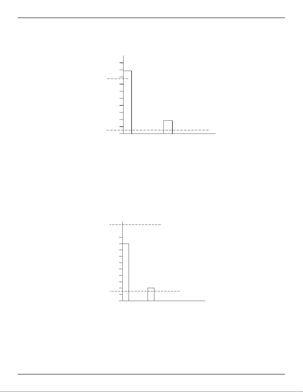
OPERATION FLT® Series FlexSwitch
Low Level Alarm Settings (Sensing Element Normally Wet)
For the low level fail safe setup the following jumpers are to be installed: J18, J20, J23, J24, J27.
WHEN ALARM 1 DETECTS LOW
LEVEL, THERE IS A POSSIBLE
OPEN ACTIVE RTD OR SHORTED
REFERENCE RTD
WHEN ALARM 2 DETECTS UNEXPECTED
FLOW THAT FORCES THE SIGNAL
BELOW THE ALARM SET POINT, THERE
IS A POSSIBLE HEATER FAILURE,
SHORTED ACTIVE RTD OR OPEN
REFERENCE RTD
A POWER FAILURE IS DETECTED IF
BOTH RELAYS ARE DE-ENERGIZED
LIQUID
MEDIA
C00534-2-2
DE-ENERGIZED
ALARM 1
SET POINT
ENERGIZED
SIGNAL
OUTPUT
ENERGIZED
ALARM 2
SET POINT
DE-ENERGIZED
5.0
4.5
4.0
3.5
3.0
2.5
2.0
1.5
1.0
0.5
0
AIR
Figure 3-7. Low Level Fail Safe Alarm
TM
The following information is assumed:
Relay is de-energized in the ALARM condition.
Alarm 1 set point is adjusted for the mean value between the air and liquid signals.
Alarm 2 set point is adjusted to approximately half of the liquid signal. (A lower setting might be needed if the liquid is moving.)
High Level Alarm Settings (Sensing Element Normally Dry)
For the high level fail safe setup the following jumpers are to be installed: J18, J20, J23, J25, J26.
DE-ENERGIZED
ALARM 2
SET POINT
ENERGIZED
SIGNAL
OUTPUT
ENERGIZED
ALARM 1
SET POINT
DE-ENERGIZED
5.0
4.5
4.0
3.5
3.0
2.5
2.0
1.5
1.0
0.5
0
AIR
WHEN ALARM 1 DETECTS HIGH LEVEL,
THERE IS A POSSIBLE HEATER FAILURE,
SHORTED ACTIVE RTD OR OPEN
REFERENCE RTD
ALARM 2 DETECTS A POSSIBLE OPEN
ACTIVE RTD OR SHORTED REFERENCE
RTD
A POWER FAILURE IS DETECTED IF
BOTH RELAYS ARE DE-ENERGIZED
LIQUID
MEDIA
C00535-2-2
Figure 3-8. High Flow Fail Safe Alarm
The following information is assumed:
Relay is de-energized in the ALARM condition.
Alarm 1 set point is adjusted for the mean value between the air and liquid signals.
Alarm 2 set point is adjusted above maximum signal output for air (not to exceed 7.0 volts).
38 Fluid Components International LLC
Page 39

FLT® Series FlexSwitchTM MAINTENANCE
4 MAINTENANCE
Warning: To avoid hazards to personnel, ensure that all environmental isolation seals are properly maintained.
Caution: The insturment contains electrostatic discharge (ESD) sensitive devices. Use standard ESD precautions when handling the
control circuit. See Chapter 2, Operation, for ESD details.
The FCI instrument requires very little maintenance. There are no moving parts or mechanical parts subject to wear in the instrument. The
sensor assembly which is exposed to the process media is all stainless steel construction and is only susceptible to chemical attack based on
the corrosion relationship of the RTD thermowell material with the process media.
Maintenance
Without detailed knowledge of the environmental parameters of the application surroundings and process media, FCI cannot make specifi c
recommendations for periodic inspection, cleaning, or testing procedures. However, some suggested general guidelines for maintenance
steps are offered below. Use operating experience to establish the frequency of each type of maintenance.
Calibration
Periodically verify the calibration of the output and re-calibrate if necessary. See Chapter 3 for instructions.
Electrical Connections
Periodically inspect cable connections on terminal strips and terminal blocks. Verify that terminal connections are tight and in good condition
with no sign of corrosion.
Remote Enclosure
Verify that the moisture barriers and seals protecting the electronics in the local and remote enclosures are adequate and that no moisture is
entering those enclosures.
Electrical Wiring
FCI recommends occasional inspection of the system’s interconnecting cable, power wiring and sensing element wiring on a common sense
basis related to the application environment. Periodically the conductors should be inspected for corrosion and the cable insulation checked
for signs of deterioration.
Sensing Element Connections
Verify that all seals are performing properly and that there is no leakage of the process media. Check for deterioration of the gaskets and
environmental seals used.
Sensing Element Assembly
Periodically remove the sensing element for inspection based on historical evidence of debris, foreign matter, or scale buildup during appropriate plant shutdown schedules and procedures. Check for corrosion, stress cracking, and/or buildup of oxides, salts, or other substances.
The thermowells must be free of excessive contaminants and be physically intact. Any debris or residue buildup could cause inaccurate
switching. Clean the sensing element with a soft brush and available solvents that are compatible with the instruments wetted metal.
Fluid Components International LLC 39
Page 40

MAINTENANCE FLT® Series FlexSwitch
TM
INTENTIONALLY LEFT BLANK
40 Fluid Components International LLC
Page 41

FLT® Series FlexSwitchTM TROUBLESHOOTING
5 TROUBLESHOOTING
Warning: Only qualifi ed personnel should attempt to test this instrument. The operator assumes all responsibilities for safe practices
while troubleshooting.
Caution: The control circuit contains electrostatic discharge (ESD) sensitive devices. Use standard ESD precautions when handling
the control circuit. See Chapter 2, Operation, for ESD details.
Tools Needed
Digital Multimeter (DMM)
Small standard screwdriver
Small phillips head screwdriver
Quick Check
• Verify that the control circuit is seated fi rmly.
• LED DS3 should be lit when power is applied and in most cases it should not be blinking.
• Ensure that the jumpers are in the correct position. See Chapter 3 for the correct positions.
(The power is factory preset for 220 Vac, the customer may need to reset jumpers for other power input.)
• Ensure that the CALIBRATE - RUN switch is in the RUN position (switch S1 positioned toward the heat sink).
• If LED DS3 fl ashes the heater power is set to high for most applications.
• Check any customer supplied fuses.
• See the troubleshooting chart in Figure 5-1 at the end of this chapter.
Non-maintenance Observations
At this point, observe the system setup to verify operation. No disassembly or testing is required at this time.
Check Serial Numbers
Verify that the serial number of the sensing element and the control circuit are the same number. The sensing element and the control circuit
are a matched set and cannot be operated independently of each other. The exception to this is if a removal and replacement have been
done for repair purposes. All calibrations and jumpers must have been done and set.
Check Input Power
Verify that the correct power source is turned on and connected. Verify that the power jumpers are correct for the application. See Chapter 3
for the correct positions.
Check the Instrument Installation
Review the information on instrument installation in Chapter 2 to verify correct mechanical and electrical installation.
Check for Moisture
Check for moisture on the control circuit or in the sensor , or control circuit enclosure. Moisture on the control circuit may cause intermittent
operation.
Check Application Design Requirements
Application design problems may occur with fi rst time application instruments, although the design should also be checked on instruments
that have been in operation for some time. If the application design does not match fi eld conditions, errors occur.
1. Review the application design with plant operation personnel and plant engineers.
2. Ensure that plant equipment such as pressure and temperature instruments conform to the actual conditions.
3. Verify operating temperature, operating pressure, line size, and process medium.
Fluid Components International LLC 41
Page 42

TROUBLESHOOTING FLT® Series FlexSwitch
If conditions and specifi cations are satisfactory, then refer to the troubleshooting chart in the back of this chapter for troubleshooting
suggestions.
Troubleshooting the Flow Element
Use Tables 5-1 and 5-2 to determine if the fl ow element is wired correctly or has failed. Turn off the input power to the instrument. Unplug
the control circuit from its socket and measure the resistances below from the terminal block socket.
If the instrument is set up in remote confi guration (fl ow element enclosure seperate from the control circuit enclosure), and the ohm readings
are incorrect, disconnect the fl ow element cable at the local (fl ow element) enclosure. Measure the resistance as shown in Table 5-2. If the
resistances are correct then the cable between the enclosures is probably bad or not connected properly (loose, corroded, or connected to the
wrong terminals).
For normally dry conditions check for moisture on the sensing element. If a component of the process media is near its saturation temperature it may condense on the sensing element. Place the sensing element where the process media is well above the saturation temperature
of any of the process gases.
NOMINAL CONTROL CIRCUIT RESISTANCE
LUG NUMBER RESISTANCE
7 TO 8 1.1 K OHM*
TM
7 TO 9 2.2 K OHM*
7 TO 10
110-120 OHM FOR FLT93-S
548-620 OHM FOR FLT93-F
8 TO 9 1.1 K OHM*
Table 5-1. Resistance at Control Circuit Terminal Block Socket
NOMINAL RESISTANCE AT LOCAL ENCLOSURE TERMINAL BLOCK
TERMINAL NO. RESISTANCE
1 TO 2
110-120 OHM FOR FLT93-S
548-620 OHM FOR FLT93-F
3 TO 4 1.1 K OHM*
3 TO 5 2.2 K OHM*
4 TO 5 1.1 K OHM*
SHIELD CONNECTED TO CONTROL CIRCUIT SOCKET ONLY. NO
CONNECTION TO LOCAL ENCLOSURE OR ITS TERMINAL BLOCK**
Table 5-2. Resistance at Flow Element enclosure Terminal Block (Remote Applications Only)
* Approximate at 80°F process temperature.
** Reference wiring diagrams in the Installation section of the manual.
42 Fluid Components International LLC
Page 43

FLT® Series FlexSwitchTM TROUBLESHOOTING
Troubleshooting the Flow Transmitter
With power applied measure 9 volts DC ±2% (8 to 10 volts) from Plug P1 Pin 1 to Pin 4. See Figure 3-2 for the location of P1.
1 Is the Yellow LED ON, OFF or BLINKING
2 Mode Switch Make sure the mode switch is in the “RUN” position.
3 Signal Voltage Observation Remove the Heater Wattage Control jumper. With a voltmeter measure the signal
4 Power Supply Check Measure the voltage at P1 terminals 2 to 4.
LED ON
Although the LED is on, it may appear dim. This is usually caused by the unit being
supplied with 115 Vac and the Input Power Jumper Confi guration set to the default
setting of 230 Vac.
Check Input power and the input power jumper confi guration:
OK: See Step 2.
NOT OK: Supply power will need to be changed to work with the control circuit or
the control circuit must be returned to FCI for reconfi guration.
LED OFF
Check the Input Power Jumper Confi guration setting and verify the input power.
OK: See Step 4
NOT OK: Supply power will need to be changed to work with the control circuit or
the control circuit must be returned to FCI for reconfi guration. Reinstall the control
circuit and restart the system and check for proper operation. If LED is still off go
to Step 4.
LED BLINKING
For Liquid Flow Applications: Line is DRY. Make sure the line is packed.
For Gas Flow Applications: Heater power set too high. Set to lower value.
For Liquid level Applications: Heater power set too high. Set to lower value.
For Liquid Interface Applications: In some cases it is necessary to set the heater
power to the maximum value to achieve the maximum signal difference between
the two liquids. For this application it is normal for the LED to blink if the element
goes dry. Go to Step 2.
OK: See Step 3.
voltage at P1 Terminals 1 and 2.
a) The voltage is 0 volts ± 25 mV: OK,
Reinstall the jumper and wait 5 minutes. Go to c) or d) which ever is applicable.
b) The voltage is out of tolerance: NOT OK,
Make sure that the serial numbers on the control board and the sensing element
match. If the serial numbers are OK then go to the “Restoring Temp Comp Adjustments” procedure in Appendix C then go to c) or d) which ever is applicable.
c) The Voltage is between 0.1 and 6 volts and changes with fl ow or level
changes:
OK. See Step 9.
d) The voltage is still about 0 volts: or the voltage is over ± 7 volts: or the
voltage is negative, between -1 and -6 volts and changes with fl ow or level
changes: Not OK,
Sensing element may be miswired or is defective. Miswiring is more common on
remote installations at the initial installation. See Step 6 for integral installation,
Step 7 for remote installations.
Voltage is 9 volts ± .2V: OK. See Step 6 for integral installation, Step 7 for
remote installations.
NOT OK. See Step 5.
Fluid Components International LLC 43
Page 44

TROUBLESHOOTING FLT® Series FlexSwitch
5 Fuse Check Turn off the power to the FLT and remove the control circuit. With an ohmmeter,
measure the continuity of the fuse F1.
Fuse has no continuity: NOT OK Replace the fuse and restart the system.
Check for proper operation. Call the factory if the fuse fails again.
Fuse has continuity: OK Control circuit is defective. Replace it with a
control circuit that has the temp comp adjusted for the particular sensing element.
Follow the “Restoring temperature compensation settings” procedure in Appendix
C and restart the system.
6 Sensor Element Check for Integral
Installation
7 Sensor Element Check for Remote
Installation
8 Sensor Balance and Temp Comp Settings
Check
9 Alarm Switch Point Settings Make sure that the jumpers are set correctly. The related settings are the “Alarm
Turn off the power and remove the control circuit. Follow the “Troubleshooting the
Flow Element” procedure in this chapter.
Sensor Failure: Call the Factory
Sensors are OK: See Step 8.
Turn off the power and remove the control circuit. Follow the “Troubleshooting the
Flow Element” procedure in this chapter.
Remote cable miswired or damaged: Repair and restart the system.
Sensor Failure: Call the Factory
Sensors are OK: See Step 8.
Turn off the power and remove the control circuit. Follow the procedure in
Appendix C to check the temp comp settings and balance adjustment.
Temp Comp Settings are Wrong: Perform the “Restore Temp Comp” Procedure.
Then perform the sensor Balancing procedure.
Temp Comp Settings are OK: Perform the Balancing procedure. Restart the
system for proper operation. See Step 9.
Duty”, “Alarm Quantity” and the “Energization”. Refer to the charts in chapter 3 or
the bottom of the control circuit.
Using the Mode Switch set to Cal, check and record the alarm settings. Compare
these setting to the signals generated by the process and make adjustment if
necessary. Refer to the Operation chapter for guidelines on setting a switch point
in your particular application.
Figure 5-1. Trouble Shooting Chart
TM
Spares
FCI recommends at least one control circuit to be kept as a spare. Depending on the number of units the customer has installed and if the
switches are critical then an entire spare switch assembly should be kept on hand. The control circuit part number is 5298-A1A1A1B2. The
dash number can be found on the control circuit, the enclosure and on the ordering paper work.
Defective Parts
Before returning any equipment to FCI, please obtain an RA number for authorization, tracking, and repair/replacement instructions. If a
return is required, remove the defective instrument, replace with a spare, calibrate, then return defective instrument to FCI freight prepaid for
disposition.
Customer Service
1. In the event of problems or inquiries regarding the instrument, contact the Regional or Country Authorized FCI Field Agent. There is an
extensive list of these representatives at the front of this manual.
2. Before contacting the FCI representative, please be sure that all the applicable information is near so that a more effective, effi cient and
timely response may be provided.
3. Refer to Appendix C for specifi c Customer Service policy provisions.
44 Fluid Components International LLC
Page 45

FLT® Series FlexSwitchTM APPENDIX A - DRAWINGS
APPENDIX A DRAWINGS
PWB Module 5298 - Dual Alarm
Fluid Components International LLC 45
Page 46

APPENDIX A - DRAWINGS FLT® Series FlexSwitch
TM
INTENTIONALLY LEFT BLANK
46 Fluid Components International LLC
Page 47

FLT® Series FlexSwitchTM APPENDIX B - GLOSSARY
APPENDIX B GLOSSARY
Abbreviations
Delta-R (DR) Differential Resistance
Delta-T (DT) Differential Temperature
DMM Digital Multimeter
DPDT Double Pole Double Throw
FCI Fluid Components Intl
HTR Heater
LED Light Emitting Diode
POT Potentiometer
RA Return Authorization
RTD Resistance Temperature Detector
SFPS Standard Feet Per Second
SPDT Single Pole Double Throw
Defi nitions
Active RTD The sensing element that is heated by the heater. The active RTD is cooled due to increases in the
process fl uid fl ow rate or density (level sensing).
Differential resistance
Delta-R (DR) The difference in resistance between the active and reference RTDs.
Differential temperature
Delta-T (DT) The difference in temperature between the active and reference RTDs.
Heater (HTR) The part of the sensing element that heats the active RTD.
Local enclosure The enclosure attached to the sensing element. (Usually contains the control circuit and mounting socket.)
Reference RTD The part of the sensing element that senses the process media temperature.
Remote enclosure An optional protective enclosure for the control circuit. Used when the control circuit must be located away
from the sensing element.
Resistance Temperature
Detector (RTD) A sensor whose resistance changes proportionally to temperature changes.
Sensing element The transducer portion of the instrument. The sensing element produces an electrical signal that is related to
the fl ow rate, density (level sensing), and temperature of the process media.
Thermowell The part of the sensing element that protects the heater and RTDs from the process fl uid.
Turndown The ratio of the upper to lower fl ow rate values.
Fluid Components International LLC 47
Page 48

APPENDIX B - GLOSSARY FLT® Series FlexSwitch
TM
INTENTIONALLY LEFT BLANK
48 Fluid Components International LLC
Page 49

FLT® Series FlexSwitchTM APPENDIX C - TEMP COMP
APPENDIX C TEMPERATURE COMPENSATION
Introduction
Temperature compensation (Temp Comp) is an essential part of the FLT FlexSwitch circuitry. When the Temp Comp is set correctly, the instrument stays accurate over a process temperature range of 100°F. The instrument is a thermal dispersion device. It relies on the temperature differential between the reference RTD, which is at the process media temperature, and the active RTD, which is heated to produce a
temperature differential (DT). For example; with constant temperature, fl ow rate, process media and heater power, the DT is reduced and
reaches a stable value. If the process media temperature goes up and all other conditions stay the same, the DT is reduced. Without Temp
Comp the circuitry would process the signal as an increased fl ow rate.
To understand Temp Comp the output signal needs to be understood fi rst. This temperature output signal is the absolute voltage drop across
the reference RTD, and proportional to temperature. The instrument uses this voltage for two purposes. The voltage drop across the reference RTD is subtracted from the voltage drop across the Active RTD to produce a voltage differential. The voltage differential is used to set
fl ow or liquid level alarms. Also, the voltage drop across the reference RTD adds to, or subtracts from, the output signal as a function of DT.
Note: In order to adjust the Temp Comp correctly certain parameters must be measured and calculated. All temperature measure-
ments should converted to degrees Fahrenheit before a temperature differential is found. These parameters and measurements will be discussed later in this appendix.
Factory Temperature Compensation Settings
A Temp Comp adjustment procedure is performed on the instrument before it is shipped. Under normal conditions this setting will not have to
be done by the customer. However, if there have been changes in environment since the instrument was ordered then the following instructions may need to be done by the customer.
Restoring Temp Comp Adjustments
When the control circuit is replaced or if the Temp Comp potentiometers are accidently moved the adjustments must be restored. There are
three adjustments that need to be made on the control circuit in order to set the Temp Comp. Two of the adjustments are done with no power
applied to the instrument and a third adjustment is done with power applied. Calibration values for each instrument are on the Temp Comp
calibration sheet that is found in the plastic page protector at the back of this manual. The calibration values are listed by the serial number
of the instrument.
Equipment Required
• 5-1/2 digit digital multimeter (DMM). (Small clip leads are desirable.)
• Adapter cable FCI part number 015664-01 for older version of the control circuit.
• Flat screw driver, capable of adjusting control circuit potentiometers.
• Temp Comp calibration values from the page protector in the back of this manual.
• Insulating varnish or equivalent to reseal the potentiometers.
Caution: The instrument contains electrostatic discharge (ESD) sensitive devices. Use standard ESD precautions when handling the
control circuit. See Chapter 2, Installation, for ESD details.
Procedure
1. Turn off the instrument power. Remove the control circuit form the socket.
2. Write down where the heater wattage control jumper is located in the area of the upper left hand side of the control circuit. Remove the
heater wattage control jumper and set it aside. Refer to Figure 3-1 for the jumper location.
3. Remove jumpers J10 and J11 at the lower side of the control circuit and set them aside.
4. Connect the DMM from TP1 (by J10), to the left jumper post of J10. Set the DMM to ohms. See Figure 3-2 for component placement.
5. Adjust potentiometer R5 (bottom center of the control circuit) until the DMM reads the ohm value for R5 as shown on the Temp Comp
calibration sheet that is in the plastic page protector in the back of this manual.
6. Remove the DMM, and reconnect it between TP2 (by J11), and the right jumper post of J11. Figure 3-1 shows jumper post location.
Fluid Components International LLC 49
Page 50

APPENDIX C - TEMP COMP FLT® Series FlexSwitch
7. Adjust pot R8 (below the yellow LED) until the ohm value for R8 is as shown on the Temp Comp Cal sheet.
8. Remove the DMM and reinstall jumpers J10 and J11. (Leave the heater jumper removed.)
Note: Steps 10 through 13 are the fl ow element balance procedure required to complete the Temp Comp restoration.
9. Connect the DMM to P1 (the adapter cable on older control circuits) with the positive lead connected to position 2 (red wire on older
control circuits) and the negative lead connected to position 2 (blue wire on older control circuits). Re-install the control circuit on the
socket. Set the DMM to volts DC.
10. Turn on the instrument power and wait fi fteen minutes for the instrument to stabilize. During this time make sure that the process media
is fl owing or the sensing elements are submerged. Do not make the following adjustment in still gas.
11. Adjust potentiometer R13 (next to R8) until the DMM reads 0 volts ±5mV.
12. Turn off the instrument power and remove the DMM. Re-install the heater jumper in its original position.
The Temp Comp adjustments are now restored. Turn on the power and make sure the instrument is functioning properly. Make adjustments
to the alarm set points if needed.
Field Temp Comp Calibration
If the application of the instrument changes the Temp Comp may need to be re-calibrated. An example of when the Temp Comp needs to be
re-calibrated is as follows: The process media is gas, the factory set Temp Comp is 40 to 140 °F. The instrument is then placed in an application that varies in temperature from 300 to 400 °F. In this case the instrument’s accuracy would be greater with a new Temp Comp calibration
performed.
Another example of where the accuracy will be affected and a Temp Comp calibration would need to be done is when the process media is
changed, i.e. from water to heavy oil.
Temp Comp calibration is possible to do in the fi eld if the test conditions are met and the data is measured correctly. However, in many applications it is diffi cult to achieve these parameters and it is easier to have the switch factory calibrated. To do the procedure the following
parameters are required:
TM
• The maximum temperature range does not exceed 100 °F.
• The maximum temperature does not exceed the instruments rated maximum temperature.
• The velocity at which the switch will alarm needs to be known.
Equipment Required
1 each DC Power Supply, 0 to 20 Vdc minimum, at 0.5 Amps.
2 each 5-1/2 Digit DMM with 4 wire clip leads.
1 each #1 Philips screw driver.
1 each #1 Flat blade screw driver.
1 each Flat screw driver, capable of adjusting control circuit potentiometers.
Insulating varnish or equivalent to reseal the potentiometers.
Procedure
1. Turn off the instrument power.
2. Install the instrument into the pipe or a test stand where it can be calibrated. Start the process media fl owing at a normal rate. Cool the
process media to the lowest temperature in the expected operating range.
3. Remove the control circuit. Disconnect the wires on terminals 6 through 10. Removal of the socket from the enclosure may be necessary
for access to the wires.
4. Connect the DMM’s and the power supply to the sensing element as shown in Figure D-1.
5. Set the power supply voltage to the proper voltage as shown in Table D-1. Turn on the power supply and check the voltage setting.
6. Stop the process media fl ow and make sure that the media is at no fl ow and then let the instrument stabilize for fi fteen minutes.
7. Record the resistance values of the sensing elements and calculate the resistance differential (DR). If DR does not exceed the maximum
DR of 280 ohms then proceed with the calibration. If the DR is above 280 ohms use the next lower heater wattage setting and let the
instrument stabilize. Recheck the DR
50 Fluid Components International LLC
Page 51

FLT® Series FlexSwitchTM APPENDIX C - TEMP COMP
8. Start the process media fl owing at the desired switch point velocity and at the low temperature, let the instrument stabilize for fi fteen
minutes.
9. Record the resistance values of the active and reference RTD’s at the low temperature.
10. Raise the temperature of the process media to the maximum expected temperature. With the instrument power on, let the instrument
stabilize for fi fteen minutes. The difference between the low and the high temperature should not exceed 100°F.
11. Record the resistance values of the active and reference RTD’s for the high temperature.
12. Calculate the Temp Comp factor with the formula shown below.
TEMP
COMP
FACTOR
The Temp Comp factor is not to exceed ±0.041.
13. If the Temp Comp factor is within tolerance, turn off the power to the instrument and stop the process media if needed. Disconnect the
DMM’s and the power supply from the instrument. Reconnect the sensing element wires to the control circuit socket and reinstall the
socket in the enclosure if it was previously removed. Do not pinch the wires between the socket and the enclosure.
14. Look up the resistance values to adjust potentiometers R5 and R8 in the Temp Comp Factor table (Table D-2). Follow the procedure in the
Restoring Temp Comp adjustment section using the values found in the table below.
15. If the calculated Temp Comp factor exceeds the allowable tolerance by a small amount (±0.01), using the maximum Temp Comp factor
may make the instrument perform satisfactorily. However, if the factor is out of tolerance by more than ±0.01 then it will be necessary to
repeat the calibration to verify the result. Continue with the adjustment procedure if the second result is within tolerance.
=
(R Reference High Temperature) - (R Reference Low Temperature)
∆R Low Temperature - ∆R High Temperature
Figure D-1. Sensing Element Calibration Connections
POWER SUPPLY SETTINGS
FLT93-S
FLT93-F
Fluid Components International LLC 51
3 Watts 1.75 Watts 0.75 Watts 0.21 Watts
Set For 18.0 Vdc Set For 13.8 Vdc Set For 9.0 Vdc Set For 4.9 Vdc
0.57 Watts 0.52 Watts 0.40 Watts 0.25 Watts
Set For 18.0 Vdc Set For 17.0 Vdc Set For 15.0 Vdc Set For 11.8 Vdc
Table D-1. Heater Voltage Settings
Page 52

APPENDIX C - TEMP COMP FLT® Series FlexSwitch
TM
TEMP COMP R5 R8
FACTOR K OHMS K OHMS
0.042 119.75 263.16
0.041 119.88 256.41
0.04 120.00 250.00
0.039 120.13 243.9
0.038 120.25 238.10
0.037 120.38 232.56
0.036 120.5 227.27
0.035 120.63 222.22
0.034 120.75 217.39
0.033 120.88 212.77
0.032 121.00 208.33
0.031 121.13 204.08
0.030 121.25 200.00
0.029 121.38 196.08
0.028 121.5 192.31
0.027 121.63 188.68
0.026 121.75 185.19
0.025 121.88 181.82
0.024 122.00 178.57
0.023 122.13 175.44
0.022 122.25 172.41
0.021 122.38 169.49
0.020 122.5 166.67
0.019 122.63 163.93
0.018 122.75 161.29
0.017 122.88 158.73
0.016 123.00 156.25
0.015 123.13 153.85
0.014 123.25 151.52
TEMP COMP R5 R8
FACTOR K OHMS K OHMS
0.013 123.38 149.25
0.012 123.50 147.06
0.011 123.63 144.93
0.010 123.75 142.86
0.009 123.88 140.85
0.008 124.00 138.89
0.007 124.13 136.99
0.006 124.25 135.14
0.005 124.38 133.33
0.004 124.50 131.58
0.003 124.63 129.87
0.002 124.75 128.21
0.001 124.88 126.58
0.000 125.00 125.00
-0.001 125.13 123.46
-0.002 125.25 121.95
-0.003 125.38 120.48
-0.004 125.50 119.05
-0.005 125.63 117.65
-0.006 125.75 116.28
-0.007 125.88 114.94
-0.008 126.00 113.64
-0.009 126.13 112.36
-0.010 126.25 111.11
-0.011 126.38 109.89
-0.012 126.50 108.70
-0.013 126.63 107.53
-0.014 126.75 106.38
-0.015 126.88 105.26
TEMP COMP R5 R8
FACTOR K OHMS K OHMS
-0.016 127.00 104.17
-0.017 127.13 103.09
-0.018 127.25 102.04
-0.019 127.38 101.01
-0.020 127.50 100.00
-0.021 127.63 99.01
-0.022 127.75 98.04
-0.023 127.88 97.09
-0.024 128.00 96.15
-0.025 128.13 95.24
-0.026 128.25 94.34
-0.027 128.38 93.46
-0.028 128.50 92.59
-0.029 128.63 91.74
-0.030 128.75 90.91
-0.031 128.88 90.09
-0.032 129.00 89.29
-0.033 129.13 88.50
-0.034 129.25 87.72
-0.035 129.38 86.96
-0.036 129.50 86.21
-0.037 129.63 85.47
-0.038 129.75 84.75
-0.039 129.88 84.03
-0.040 130.00 83.33
-0.041 130.13 82.64
-0.042 130.25 81.97
Table D-2. Temp Comp Factor Table
52 Fluid Components International LLC
Page 53

FLT® Series FlexSwitchTM APPENDIX D - CUSTOMER SERVICE
APPENDIX D CUSTOMER SERVICE
Customer Service/ Technical Support
FCI provides full in-house technical support. Additional technical representation is also provided by FCI fi eld representatives. Before contacting a fi eld or in-house representative, please perform the troubleshooting techniques outlined in this document.
By Mail
Fluid Components International LLC
1755 La Costa Meadows Dr.
San Marcos, CA 92078-5115 USA
Attn: Customer Service Department
By Phone
Contact the area FCI regional representative. If a fi eld representative is unable to be contacted or if a situation is unable to be resolved,
contact the FCI Customer Service Department toll free at
1 (800) 854-1993.
By Fax
To describe problems in a graphical or pictorial manner, send a fax including a phone
or fax number to the regional representative. Again, FCI is available by facsimile if all possibilities have been exhausted with the authorized factory representative. Our Fax number is 1 (760) 736-6250; it is available 7 days a week, 24 hours a day.
By E-Mail
FCI Customer Service can be contacted by e-mail at: techsupport@fl uidcomponents.com.
Describe the problem in detail making sure a telephone number and best time to be contacted is stated in the e-mail.
International Support
For product information or product support outside the contiguous United States, Alaska, or Hawaii, contact your country’s FCI International Representative or the one nearest to you.
After Hours Support
For product information visit FCI’s Worldwide Web at www.fl uidcomponents.com. For product support call 1 (800) 854-1993 and follow
the prerecorded instructions.
Point of Contact
The point of contact for service, or return of equipment to FCI is your authorized FCI sales/service offi ce. To locate the offi ce nearest you,
please go to www.fl uidcomponents.com.
Warranty Repairs or Returns
FCI prepays ground transportation charges for return of freight to the customer’s door. FCI reserves the right to return equipment by the carrier
of our choice.
International freight, handling charges, duty/entry fees for return of equipment are paid by the customer.
Non-Warranty Repairs or Returns
FCI returns repaired equipment to the customer either collect or prepaid and adds freight charges to the customer invoice.
Fluid Components International LLC 53
Page 54

APPENDIX D - CUSTOMER SERVICE FLT® Series FlexSwitch
Return to Stock Equipment
The customer is responsible for all shipping and freight charges for equipment that is returned to FCI stock from the customer site. These
items will not be credited to customer’s account until either all freight charges are cleared or until the customer agrees to have any freight
costs incurred by FCI deducted, along with applicable return to stock charges, from the credit invoice. (Exceptions are made for duplicate
shipments made by FCI.)
If any repair or return equipment is received at FCI, freight collect, without prior factory consent, FCI bills the sender for these charges.
Field Service Procedures
Contact an FCI fi eld representative to request fi eld service.
A fi eld service technician is dispatched to the site from either the FCI factory or one of the FCI representative offi ces. After the work is complete, the technician completes a preliminary fi eld service report at the customer site and leaves a copy with the customer.
Following the service call, the technician completes a formal, detailed service report. The formal report is mailed to the customer within fi ve
days of the technician’s return to the factory or offi ce.
Field Service Rates
All fi eld service calls are billed at the prevailing rates as listed in the FCI Price Book unless specifi cally excepted by the FCI Customer Service
Manager. FCI reserves the right to bill for travel times at FCI’s discretion.
Customers are charged for shipping costs related to the transfer of equipment to and from the job site. They are also invoiced for fi eld service
work and travel expenses by FCI’s Accounting Department.
TM
54 Fluid Components International LLC
Page 55

FLT® Series FlexSwitchTM APPENDIX D - CUSTOMER SERVICE
RA #______________
1755 La Costa Meadows Drive, San Marcos, CA 92078-5115 USA
760-744-6950 / 800-854-1993 / Fax: 760-736-6250
Web Site: www.fluidcomponents.com
E-mail: techsupport@fl uidcomponents.com
Return Authorization Request
1. Return Customer Information
Returning Company’s Name: _____________________________ Phone# __________________________________
Return Contact Name: __________________________________ Fax # ____________________________________
Email Address: ________________________________________________________________________________
2. Return Address
Bill To: _______________________________________ Ship To: _______________________________________
____________________________________________ ______________________________________________
____________________________________________ ______________________________________________
____________________________________________ ______________________________________________
3. Mandatory End User Information
Contact: ______________________ Company: _____________________________ Country: ________________
4. Return Product Information
Model No: ____________________________________ Serial No(s): ____________________________________
Failure Symptoms
____________________________________________________________________________________________
What Trouble Shooting Was Done Via Phone or Field Visit by FCI: _________________________________________
____________________________________________________________________________________________
FCI Factory Technical Service Contact: _____________________________________________________________
5. Reason For Return
Recalibrate (New Data) Recalibrate (Most Recent Data) Other
(Note: A new Application Data Sheet (ADS) must be submitted for all recalibrations and re-certifi cations)
(Detailed Description Required)
: ____________________________________________________
Sensor Element Electronics As Found Testing Credit
6. Payment Via Faxed Purchase Order
(Note: A priced quotation is provided for all Non-Warranty repairs after equipment has been evaluated. All Non-Warranty repairs
are subject to a minimum evaluation charge of $250.00)
Factory Return Shipping Address: Fluid Components International LLC
1755 La Costa Meadows Drive
San Marcos, CA 92078-5115
Attn: Repair Department
RA #____________
Fluid Components International LLC 55
Page 56

APPENDIX D - CUSTOMER SERVICE FLT® Series FlexSwitch
TM
The following Return Authorization Request form and Decontamination Statement
a Return Authorization Number will be issued. The signed Decontamination Statement and applicable MSDS Sheets must be in-
before
cluded with the shipment. FCI will either fax, email or telephone you with the Return Authorization Number upon receipt of the signed
forms.
Packing Procedures
1. Electronics should be wrapped in an anti-static or static-resistant bag, then wrapped in protective bubble wrap and surrounded
with appropriate dunnage* in a box. Instruments weighing more than 50 lbs., or extending more than four feet, should be secured in wooden crates by bolting the assemblies in place.
2. The sensor head must be protected with pvc tubing, or retracted the full length of the probe, locked and secured into the Packing Gland Assembly (cap screws tightened down).
3. FCI can supply crates for a nominal fee.
4. No more than four (4) small units packaged in each carton.
5. FCI will not be held liable for damage caused during shipping.
6. To ensure immediate processing mark the RA number on the outside of the box. Items without an RA number marked on the box
or crate may be delayed.
7. Freight must be “PrePaid” to FCI receiving door.
* Approriate dunnage as defi ned by UPS, will protect package contents from a drop of 3 feet.
MUST be completed, signed and faxed back to FCI
*** Decontamination Statement *** This Section Must Be Completed ***
Exposure to hazardous materials is regulated by Federal, State, County and City laws and regulations. These laws provide FCI’s
employees with the “Right to Know” the hazardous or toxic materials or substances in which they may come in contact while handling returned products. Consequently, FCI’s employees must have access to data regarding the hazardous or toxic materials or
substances the equipment has been exposed to while in a customer’s possession. Prior to returning the instrument for evaluation/
repair, FCI requires thorough compliance with these instructions. The signer of the Certifi cate must be either a knowledgeable Engineer, Safety Manager, Industrial Hygenist or of similar knowledge or training and responsible for the safe handling of the material to
which the unit has been exposed. Returns without a legitimate Certifi cation of Decontamination, and/or MSDS when required, are
unacceptable and shall be returned at the customer’s expense and risk. Properly executed Certifi cations of Decontamination must
be provided before a repair authorization (RA) number will be issued.
Certifi cation Of Decontamination
I certify that the returned item(s) has(have) been thoroughly and completely cleaned. If the returned item(s) has(have) been exposed to hazardous or toxic materials or substances, even though it (they) has (have) been thoroughly cleaned and decontaminated,
the undersigned attests that the attached Material Data Safety Sheet(s) (MSDS) covers said materials or substances completely.
Furthermore, I understand that this Certifi cate, and providing the MSDS, shall not waive our responsibility to provide a neutralized,
decontaminated, and clean product for evaluation/repair at FCI. Cleanliness of a returned item or acceptability of the MSDS shall
be at the sole discretion of FCI. Any item returned which does not comply with this certifi cation shall be returned to your location
Freight Collect and at your risk.
This certifi cation must be signed by knowledgeable personnel responsible for maintaining or managing the safety program at
your facility.
Process Flow Media _____________________________________________________________________________________
Product was or may have been exposed to the following substances: _______________________________________________
Print Name_____________________________________________________________________________________________
Authorized Signature ___________________________________________ Date _____________________________________
Company Title __________________________________________________________________________________________
Visit FCI on the Worldwide Web: www.fluidcomponents.com
1755 La Costa Meadows Drive, San Marcos, California 92078-5115 USA ‡ Phone: 760-744-6950 ‡ 800-854-1993 ‡ Fax: 760-736-6250
FCI Document No. 05CS000004D [U]
56 Fluid Components International LLC
Page 57

FLT® Series FlexSwitchTM APPENDIX D - CUSTOMER SERVICE
WARRANTIES
Goods furnished by the Seller are to be within the limits and of the sizes published by the Seller and subject to the
Seller’s standard tolerances for variations. All items made by the Seller are inspected before shipment, and should
any of said items prove defective due to faults in manufacture or performance under Seller approved applications,
or fail to meet the written specifi cations accepted by the Seller, they will be replaced or repaired by Seller at no
charge to Buyer provided return or notice of rejection of such material is made within a reasonable period but in no
event longer than three (1) years for non-calibration defects and one (1) year for calibration defects from date of shipment to Buyer, and provided further, that an examination by Seller discloses to Seller’s reasonable satisfaction that
the defect is covered by this warranty and that the Buyer has not returned the equipment in a damaged condition
due to Buyer’s or Buyer’s employees’, agents’, or representatives’ negligence and Buyer has not tampered, modifi ed,
redesigned, misapplied, abused, or misused the goods as to cause the goods to fail. In addition, this warranty shall
not cover damage caused by Buyer’s exposure of the goods to corrosive or abrasive environments. Moreover, Seller
shall in no event be responsible for (1) the cost or repair of any work done by Buyer on material furnished hereunder
(unless specifi cally authorized in writing in each instance by Seller), (2) the cost or repair of any modifi cations added
by a Distributor or a third party, (3) any consequential or incidental damages, losses, or expenses in connection with
or by reason of the use of or inability to use goods purchased for any purpose, and Seller’s liability shall be specifi cally limited to free replacement, or refund of the purchase price, at Seller’s option, provided return or rejection of the
goods is made consistent with this paragraph, and the Seller shall in no event be liable for transportation, installation,
adjustment, loss of good will or profi ts, or other expenses which may arise in connection with such returned goods,
or (4) the design of products or their suitability for the purpose for which they are intended or used. Should the Buyer
receive defective goods as defi ned by this paragraph, the Buyer shall notify the Seller immediately, stating full particulars in support of his claim, and should the Seller agree to a return of the goods, the Buyer shall follow Seller’s
packaging and transportation directions explicitly. In no case are the goods to be returned without fi rst obtaining a
return authorization from the Seller. Any repair or replacement shall be at Seller’s factory, unless otherwise directed,
and shall be returned to Seller transportation prepaid by Buyer. If the returned goods shall prove defective under this
clause they will be replaced or repaired by Seller at no charge to Buyer provided the return or rejection of such material is made within a reasonable period, but in no event longer than (1) year from the date of shipment of the returned
goods or the unexpired terms of the original warranty period whichever is later. If the goods prove to be defective
under this paragraph, the Buyer shall remove the goods immediately from the process and prepare the goods for
shipment to Seller. Continued use or operation of defective goods is not warranted by Seller and damage occurring
due to continued use or operation shall be for Buyer’s account. Any description of the goods contained in this offer
is for the sole purpose of identifying them, and any such description is not part of the basis of the bargain, and does
not constitute a warranty that the goods will conform to that description. The use of any sample or model in connection with this offer is for illustrative purposes only, is not part of the basis of the bargain, and is not to be construed
as a warranty that the goods will conform to the sample or model. No affi rmation of that fact or promise made by the
Seller, whether or not in this offer, will constitute a warranty that the goods will conform to the affi rmation or promise. THIS WARRANTY IS EXPRESSLY IN LIEU OF ANY AND ALL OTHER EXPRESS OR IMPLIED WARRANTIES WITH
RESPECT TO THE GOODS OR THEIR INSTALLATION, USE, OPERATION, REPLACEMENT OR REPAIR, INCLUDING ANY
IMPLIED WARRANTY OF MERCHANTABILITY OR FITNESS OF PURPOSE; AND THE GOODS ARE BEING PURCHASED
BY BUYER “AS IS”. SELLER WILL NOT BE LIABLE BY VIRTUE OF THIS WARRANTY OR OTHERWISE FOR ANY SPECIAL,
INCIDENTAL OR CONSEQUENTIAL LOSS OR DAMAGE RESULTING FROM THE USE OR LOSS OF USE OF THE GOODS.
Fluid Components International LLC 57
Page 58

FCI’s Complete Customer Commitment. Worldwide
ISO 9001 and AS9100 Certifi ed
Visit FCI on the Worldwide Web: www.fl uidcomponents.com
FCI World Headquarters
1755 La Costa Meadows Drive | San Marcos, California 92078 USA | Phone: 760-744-6950 Toll Free (US): 800-854-1993 Fax: 760-736-6250
FCI Europe
Persephonestraat 3-01 | 5047 TT Tilburg, The Netherlands | Phone: 31-13-5159989 Fax: 31-13-5799036
FCI Measurement and Control Technology (Beijing) Co., LTD | www.fl uidcomponents.cn
Room 107, Xianfeng Building II, No.7 Kaituo Road, Shangdi IT Industry Base, Haidian District | Beijing 100085, P. R. China
Phone: 86-10-82782381 Fax: 86-10-58851152
This document contains confi dential technical data, including trade secrets and proprietary information which is the property of Fluid
Components International LLC (FCI). Disclosure of this data to you is expressly conditioned upon your assent that its use is limited to use within your
company only (and does not include manufacture or processing uses). Any other use is strictly prohibited without the prior written consent of FCI.
© Copyright 2011 by Fluid Components International LLC. All rights reserved.
Manufactured in accordance with one or more of the following patents: 5,600,528; 6,340,243. FCI is a registered trademark of Fluid Components International LLC. Information subject to change without notice.
Notice of Proprietary Rights
Fluid Components International LLC 06EN003409 Rev. -
 Loading...