

Page 1

Coriolis mass flowmeter
CMU
CT
Operating Manual
Please read the instructions carefully and store them in a safe place
CMU & CT OPERATING MANUAL
Part No 06EN003380 rev 1.6
Page 1 of 112
Page 2

INTRODUCTION ............................................................................................................ 9
I. Shipping and storage; product inspection............................................................................................. 9
II. Warranty ............................................................................................................................................ 9
III. Application domain the operating manual .........................................................................................9
IV. Measures to be taken before sending your device to the manufacturer for repair............................ 9
V. Supplementary operating instructions regarding the HART® interface ............................................ 9
1. STEPS PRIOR TO OPERATION......................................................................... 10
1.1 Installation and servicing ................................................................................................................. 11
1.2 Safety advisory for the user ............................................................................................................. 11
1.3 Hazard warnings.............................................................................................................................. 11
1.3.1 Danger...................................................................................................................................... 11
1.3.2 Warning .................................................................................................................................... 11
1.3.3 Caution ..................................................................................................................................... 12
1.3.4 Note .......................................................................................................................................... 12
1.4 Proper use of the device.................................................................................................................. 12
1.5 Returning your flowmeter for servicing or calibration ...................................................................... 12
1.6 Replacement of the transmitter electronics ..................................................................................... 13
2. IDENTIFICATION ................................................................................................ 13
3. THE CMU SENSOR ............................................................................................ 14
3.1 Application domain of the CMU sensor ...........................................................................................14
3.2 Mode of operation............................................................................................................................ 14
3.2.1 Measuring principle .................................................................................................................. 14
3.2.2 System configuration................................................................................................................ 14
3.2.3 Input.......................................................................................................................................... 14
3.3 Custody transfer operations ............................................................................................................ 14
3.4 Performance characteristics of the CMU sensor............................................................................. 15
3.4.1 Reference conditions................................................................................................................ 15
3.4.2 CMU flow ranges ...................................................................................................................... 15
3.4.3 Density measurement............................................................................................................... 16
3.4.4 Accuracy................................................................................................................................... 16
3.4.5 Pressure loss CMU................................................................................................................... 17
3.4.6 Ambient temperature ................................................................................................................ 18
3.4.7 Ambient temperature range...................................................................................................... 18
Page 2 of 112
CMU & CT OPERATING MANUAL
Page 3

3.4.8 Storage temperature ................................................................................................................ 18
3.4.9 Climatic category...................................................................................................................... 18
3.4.10 Ingress protection..................................................................................................................... 18
3.5 Operating conditions........................................................................................................................ 18
3.5.1 Installation ................................................................................................................................ 18
3.5.2 Installation positions ................................................................................................................. 19
3.5.3 Assessment of installation position .......................................................................................... 20
3.5.4 Pressure surges ....................................................................................................................... 21
3.5.5 Using the device with hazardous fluids.................................................................................... 21
3.5.6 Vibration stability ...................................................................................................................... 21
3.6 Process conditions .......................................................................................................................... 23
3.6.1 Process temperature ................................................................................................................ 23
3.6.2 Physical state ........................................................................................................................... 23
3.6.3 Viscosity ................................................................................................................................... 23
3.6.4 Gas content .............................................................................................................................. 23
3.6.5 Process temperature range...................................................................................................... 23
3.6.6 Process pressure range ........................................................................................................... 23
3.6.7 Outlet pressure......................................................................................................................... 23
3.7 Connection to the transmitter .......................................................................................................... 23
3.7.1 Integral mount configuration..................................................................................................... 23
3.7.2 Remote mount configuration .................................................................................................... 23
3.8 Construction details ......................................................................................................................... 24
3.8.1 Dimensions and weight ............................................................................................................ 24
3.8.2 Dimension drawing for the types CMU-C to CMU-H................................................................ 26
3.8.2.1 Standard version dimension drawing................................................................................ 26
3.8.2.2 Integral mount version up to 150 °C (302 °F) ................................................................... 26
3.8.2.3 Remote mount version dimension drawing....................................................................... 27
3.8.2.4 Remote mount version dimension drawing up to 180 °C (356 °F) ................................... 27
3.8.2.5 Remote mount version dimension drawing up to 260 °C (500 °F) ................................... 28
3.8.3 Dimension drawing for the types CMU-J to CMU-R ................................................................ 28
3.8.3.1 Standard version dimension drawing................................................................................ 28
3.8.3.2 Integral mount configuration up to 180 °C (356°F) ........................................................... 29
3.8.3.3 Remote mount version dimension drawing....................................................................... 29
3.8.3.4 Remote mount version dimension drawing up to 180 °C (356°F) .................................... 30
3.8.3.5 Remote mount version up to 260 °C (500°F).................................................................... 30
3.8.4 Heater dimension drawings for CMU-J up to CMU-R.............................................................. 31
3.8.4.1 Heater for standard version .............................................................................................. 31
3.8.4.2 Heater for integral mount version up to 150 °C (302°F) ................................................... 31
3.8.4.3 Heater for remote mount version ...................................................................................... 32
3.8.4.4 Heater for remote mount version up to 180 °C (356°F) .................................................... 32
3.8.4.5 Heater for remote mount version up to 260 °C (500 °F) ................................................... 33
3.8.5 Material..................................................................................................................................... 33
3.9 Sensor CMU approvals ................................................................................................................... 34
3.9.1 Explosion protection ................................................................................................................. 34
3.9.2 CE marking............................................................................................................................... 34
3.9.3 Custody transfer operations .....................................................................................................34
4. COMMISSIONING................................................................................................34
4.1 Zero point calibration ....................................................................................................................... 34
CMU & CT OPERATING MANUAL
Part No 06EN003380 rev 1.6
Page 3 of 112
Page 4

4.2 Startup conditions ............................................................................................................................ 34
5. APPLICATION DOMAIN OF THE CT TRANSMITTER........................................ 35
6. CT TRANSMITTER: MODE OF OPERATION AND CONFIGURATION ............. 35
6.1 Measuring principle.......................................................................................................................... 35
6.2 System configuration ....................................................................................................................... 36
6.2.1 DSB data memory module ....................................................................................................... 36
7. INPUT.................................................................................................................. 37
7.1 Measured variable ........................................................................................................................... 37
7.2 Measuring range.............................................................................................................................. 37
8. OUTPUT.............................................................................................................. 38
8.1 Output signal.................................................................................................................................... 38
8.2 Failure signal ................................................................................................................................... 38
8.3 Load ................................................................................................................................................. 39
8.4 Damping........................................................................................................................................... 39
8.5 Low flow cutoff ................................................................................................................................. 39
9. CT PERFORMANCE CHARACTERISTICS......................................................... 39
9.1 Reference conditions....................................................................................................................... 39
9.2 Measured error ................................................................................................................................ 39
9.3 Repeatability error ........................................................................................................................... 39
9.4 Influence of ambient temperature.................................................................................................... 39
10. CT OPERATING CONDITIONS........................................................................... 40
10.1 Installation conditions and cable glands ...................................................................................... 40
10.2 Environmental conditions............................................................................................................. 40
10.2.1 Ambient temperature ................................................................................................................ 40
10.2.2 Ambient temperature range...................................................................................................... 40
10.2.3 Storage temperature................................................................................................................. 40
10.2.4 Ingress protection ..................................................................................................................... 40
10.3 Process conditions....................................................................................................................... 41
10.3.1 Fluid temperature ..................................................................................................................... 41
Page 4 of 112
CMU & CT OPERATING MANUAL
Page 5

10.3.2 Physical state ........................................................................................................................... 41
10.3.3 Viscosity ................................................................................................................................... 41
10.3.4 Fluid temperature limit.............................................................................................................. 41
10.3.5 Flow rate limit ........................................................................................................................... 41
10.3.6 Pressure loss............................................................................................................................ 41
11. CONSTRUCTION DETAILS.................................................................................42
11.1 Type of construction/dimensions .................................................................................................42
11.2 Weight.......................................................................................................................................... 43
11.3 Material ........................................................................................................................................ 43
11.4 End connection ............................................................................................................................ 43
11.5 Electrical connection.................................................................................................................... 44
11.5.1 CT connections ........................................................................................................................ 44
11.5.2 Wiring diagram ......................................................................................................................... 46
11.5.2.1 Wiring diagram for the integral mount configuration of sensor and CT ............................ 46
11.5.2.2 Wiring diagram for the remote mount configuration of sensor and CT............................. 47
11.5.3 HART®...................................................................................................................................... 48
11.5.4 Communication via SensorPort................................................................................................ 48
12. CONTROL UNIT BE2 ...........................................................................................49
12.1 Introduction .................................................................................................................................. 49
12.2 Display ......................................................................................................................................... 49
12.3 Operating modes ......................................................................................................................... 50
12.4 Operation ..................................................................................................................................... 50
12.4.1 Operator interface .................................................................................................................... 50
12.4.2 The keys and their functions ....................................................................................................51
12.4.3 Functional classes, functions and parameters......................................................................... 52
12.4.3.1 Selection window/make a selection .................................................................................. 52
12.4.3.2 Input window/modify a value ............................................................................................. 53
12.4.3.3 Passwords......................................................................................................................... 53
13. CT TRANSMITTER FUNCTIONS.........................................................................54
13.1 MEASURED VALUES functional class........................................................................................ 55
13.1.1 Mass flow.................................................................................................................................. 56
13.1.2 Volume flow.............................................................................................................................. 56
13.1.3 Counter forward........................................................................................................................ 56
13.1.4 Counter reverse........................................................................................................................ 56
13.1.5 Density...................................................................................................................................... 57
13.1.6 Temperature............................................................................................................................. 57
13.1.7 Elapsed time............................................................................................................................. 57
13.1.8 Mass flow + Counter forward ................................................................................................... 57
13.1.9 Mass flow + Density ................................................................................................................. 58
13.1.10 Mass flow + Temperature..................................................................................................... 58
13.1.11 Volume flow + Counter forward ............................................................................................ 58
CMU & CT OPERATING MANUAL
Part No 06EN003380 rev 1.6
Page 5 of 112
Page 6

13.1.12 Volume flow + Density .......................................................................................................... 58
13.1.13 Display mode during startup ................................................................................................. 59
13.1.14 Raw values ........................................................................................................................... 59
13.2 PASSWORD functional class ...................................................................................................... 60
13.2.1 Customer password.................................................................................................................. 60
13.2.2 Change customer password..................................................................................................... 61
13.2.3 Service password ..................................................................................................................... 61
13.3 COUNTER functional class.......................................................................................................... 62
13.3.1 Unit of counters ........................................................................................................................ 63
13.3.2 Reset counters ......................................................................................................................... 63
13.4 MEASUREMENT PROCESSING functional class ...................................................................... 64
13.4.1 Damping ................................................................................................................................... 65
13.4.2 Low flow cut-off......................................................................................................................... 65
13.4.3 Low flow cut-off hysteresis ....................................................................................................... 65
13.4.4 Zero point calibration................................................................................................................ 66
13.5 FLOW functional class ................................................................................................................. 67
13.5.1 Mass flow QM unit .................................................................................................................... 68
13.5.2 Mass flow QM range................................................................................................................. 68
13.5.3 Mass flow QM limit MIN............................................................................................................ 69
13.5.4 Mass flow QM limit MAX........................................................................................................... 69
13.5.5 Mass flow QM limit hysteresis .................................................................................................. 69
13.5.6 Volume flow QV unit ................................................................................................................. 70
13.5.7 Volume flow QV range.............................................................................................................. 70
13.6 DENSITY functional class............................................................................................................ 71
13.6.1 Density measurement on/off .................................................................................................... 72
13.6.2 Density unit............................................................................................................................... 73
13.6.3 Density lower-range value........................................................................................................ 74
13.6.4 Density upper-range value .......................................................................................................74
13.6.5 Density limit MIN....................................................................................................................... 74
13.6.6 Density limit MAX ..................................................................................................................... 75
13.6.7 Density limit hysteresis ............................................................................................................. 75
13.6.8 Density limit for empty pipe ...................................................................................................... 75
13.6.9 Fixed density ............................................................................................................................ 76
13.6.10 Reference/process density display ....................................................................................... 76
13.6.11 Temperature coefficient........................................................................................................ 76
13.6.12 Reference temperature ......................................................................................................... 77
13.6.13 Reference pressure ..............................................................................................................77
13.7 TEMPERATURE functional class ................................................................................................ 78
13.7.1 Temperature unit ...................................................................................................................... 79
13.7.2 Temperature lower-range value ............................................................................................... 79
13.7.3 Temperature upper-range value............................................................................................... 79
13.7.4 Temperature limit MIN.............................................................................................................. 80
13.7.5 Temperature limit MAX............................................................................................................. 80
13.7.6 Max. measured temperature .................................................................................................... 80
13.8 PULSE OUTPUT functional class................................................................................................ 81
13.8.1 Pulse or frequency output ........................................................................................................ 81
13.8.2 Pulse output unit....................................................................................................................... 82
13.8.3 Pulse value ............................................................................................................................... 82
13.8.4 Pulse width ............................................................................................................................... 83
Page 6 of 112
CMU & CT OPERATING MANUAL
Page 7

13.9 STATUS functional class ............................................................................................................. 84
13.9.1 Status output active state ......................................................................................................... 85
13.9.2 Status output 1 assignment......................................................................................................85
13.9.3 Status output 2 assignment......................................................................................................86
13.9.4 Binary input assignment........................................................................................................... 86
13.10 CURRENT OUTPUTS functional class ....................................................................................... 87
13.10.1 Current output I1 0/4 to 20 mA ............................................................................................. 88
13.10.2 Current output I1 alarm.........................................................................................................88
13.10.3 Current output I1 assignment ............................................................................................... 88
13.10.4 Current output I2 0/4 to 20 mA ............................................................................................. 89
13.10.5 Current output I2 alarm.........................................................................................................90
13.10.6 Current output I2 assignment ............................................................................................... 90
13.11 SIMULATION functional class .....................................................................................................91
13.11.1 Simulation on/off ................................................................................................................... 92
13.11.2 Direct simulation ................................................................................................................... 92
13.11.3 Measured value simulation................................................................................................... 93
13.11.3.1 Simulation mass flow QM abs ......................................................................................... 93
13.11.3.2 Density simulation............................................................................................................ 93
13.11.3.3 Temperature measurement simulation............................................................................ 93
13.11.4 Direct simulation of outputs .................................................................................................. 94
13.11.4.1 Status output simulation .................................................................................................. 94
13.11.4.2 Pulse output simulation.................................................................................................... 94
13.11.4.3 Simulation current output I1............................................................................................. 94
13.11.4.4 Simulation current output I2............................................................................................. 94
13.12 SELF-TEST function class........................................................................................................... 95
13.12.1 Sensor test on/off.................................................................................................................. 96
13.12.2 Max. deviation of excitation .................................................................................................. 96
13.12.3 Self-test calibration ............................................................................................................... 96
13.12.4 Monitoring of sensor amplitude and excitation current......................................................... 96
13.13 UMC TRANSMITTER SETTINGS functional class ..................................................................... 97
13.13.1 Language .............................................................................................................................. 98
13.13.2 Serial number ....................................................................................................................... 98
13.13.3 Software version................................................................................................................... 98
13.13.4 Reset system error ............................................................................................................... 98
13.13.5 Profibus/Modbus device address ......................................................................................... 99
13.14 SENSOR SETTINGS functional class ....................................................................................... 100
13.14.1 Sensor constant C .............................................................................................................. 100
13.14.2 Sensor material................................................................................................................... 101
13.14.3 Flow direction...................................................................................................................... 102
14. USE OF THE CT FOR CUSTODY TRANSFER OPERATIONS.........................103
14.1 Programming the transmitter ..................................................................................................... 103
14.2 Binary input (resetter) ................................................................................................................ 103
14.3 Self-test error ............................................................................................................................. 103
14.4 Verification stamp/stamp position .............................................................................................. 104
CMU & CT OPERATING MANUAL
Part No 06EN003380 rev 1.6
Page 7 of 112
Page 8

14.5 HART® communication in Custody transfer mode..................................................................... 104
15. CT TRANSMITTER ERROR MESSAGES......................................................... 105
15.1 Standard operating mode .......................................................................................................... 105
15.2 Custody transfer mode............................................................................................................... 105
15.3 List of error messages................................................................................................................ 105
15.3.1 Display of self-test errors........................................................................................................ 105
15.3.2 Display of system error........................................................................................................... 108
16. CERTIFICATES AND APPROVALS.................................................................. 110
17. STANDARDS AND AUTHORIZATIONS............................................................ 110
17.1 General standards and directives .............................................................................................. 110
17.2 Electromagnetic compatibility .................................................................................................... 110
17.3 Ex-Approval transmitter.............................................................................................................. 110
18. DECONTAMINATION CERTIFICATE FOR DEVICE CLEANING ..................... 111
Page 8 of 112
CMU & CT OPERATING MANUAL
Page 9

Introduction
I. Shipping and storage; product inspection
Shipping and storage
The device is to be safeguarded against dampness, dirt, impact and damage.
Product inspection
Upon receipt of the product, check the contents of the box and the product particulars against the information on the delivery slip and order form so as to ensure that all ordered components have been supplied. Notify us of any shipping damage immediately upon receipt of the product. Any damage claim received at a later time will not be honored.
II. Warranty
Your flowmeter was manufactured in accordance with the highest quality standards and was thoroughly
tested prior to shipment. However, in the event any problem arises with your device, we will be happy to
resolve the problem for you as quickly as possible under the terms of the warranty which can be found in
the terms and conditions of delivery. Your warranty will only be honored if the device was installed and
operated in accordance with the instructions for your device. Any mounting, commissioning and/or maintenance work is to be carried out by qualified and authorized technicians only.
III. Application domain the operating manual
The present manual applies to Coriolis mass flowmeters that are operated in conjunction with the CT
transmitter.
IV. Measures to be taken before sending your device to the manufacturer for repair
It is important that you do the following before shipping your flowmeter to Fluid Components Intl for repair:
• Enclose a description of the problem with your device. Describe in as much detail as possible the
application and the physical and chemical properties of the fluid.
• Remove any residues from the device and be sure to clean the seal grooves and recesses thor-
oughly. This is particularly important if the fluid is corrosive, toxic, carcinogenic, radioactive or other-
wise hazardous.
The operator is liable for any substance removal or personal damage costs arising from inadequate
cleaning of a device that is sent for repair.
V. Supplementary operating instructions regarding the HART® interface
For information regarding operation of the transmitter using the HART
tion of the CT transmitter using the HART
®
hand-held terminal.”
®
hand-held terminal, see “Opera-
CMU & CT OPERATING MANUAL
Page 9 of 112
Part No 06EN003380 rev 1.6
Page 10

1. Steps prior to operation
It is essential that you read these operating instructions before installing and operating the device. The device is to be installed and serviced by a qualified technician
only. The CT transmitter is to be used exclusively to measure mass and volume
flow, as well as liquid and gas density and temperature, in conjunction with a CMM,
CMB or CMU sensor.
Downloading of the present document from our web site
and printing out this document is allowed only for purposes of using our mass flowmeters. All rights reserved. No instructions, wiring diagrams, and/or supplied software, or any portion
thereof, may be produced, stored, in a retrieval system or transmitted by any means, electronic, mechanical, photocopying or otherwise, without the prior written permission of FCI.
Although the materials in the present document were prepared with extreme care, errors cannot be ruled
out. Hence, neither the company, the programmer nor the author can be held legally or otherwise responsible for any erroneous information and/or any loss or damage arising from the use of the information enclosed.
FCI extends no express or implied warranty in regard to the applicability of the present document for any
purpose other than that described.
We plan to optimize and improve the products described and in so doing will incorporate not only our own
ideas but also, and in particular, any suggestions for improvement made by our customers. If you feel that
there is any way in which our products could be improved, please send your suggestions to the following
address:
FCI Fluid Components International LLC
Coriolis Product Manager
1755 La Costa Meadows Drive
San Marcos, CA 92078
or:
via fax: 760 - 736 - 6250
via E-mail:
www.fluidcomponents.com/, where you will also find contact information for the FCI representative for
your area. For factory direct questions, contact us at
mailto:techsupport@fluidcomponents.com
We reserve the right to change the technical data in this manual in light of any technical progress that might be made. For updates regarding this product, visit our website at
mailto:info@fluidcomponents.com.
www.fluidcomponents.com/
Page 10 of 112
CMU & CT OPERATING MANUAL
Page 11

1.1 Installation and servicing
The devices described in this manual are to be installed and serviced by qualified technical personnel.
Warning
Before servicing the device, it must be completely switched off, and disconnected from all
peripheral devices. The technician must also check to ensure that the device is completely off-circuit. Only original replacement parts are to be used.
Fluid Components International accepts no liability for any loss or damage of any kind arising
from improper operation of any product, improper handling or use of any replacement part, or
from external electrical or mechanical effects, overvoltage or lightning. Any such improper operation, use or handling shall automatically invalidate the warranty for the product concerned.
In the event a problem arises with your device, please contact us at one of the following numbers to arrange to have your device repaired:
Phone: 760 – 744 - 6950
Fax: 760 – 736 - 6250
Contact our customer service department if your device needs repair or if you need assistance in diagnosing a problem with your device
1.2 Safety advisory for the user
The present document contains the information that you need in order to operate the CMU Series Coriolis
mass flowmeter properly. The document is intended for use by qualified personnel. This means personnel who are qualified to operate the device described herein safely, including
trical engineers, or service technicians who are conversant with the safety regulations pertaining to the
use of electrical and automated technical devices and with the applicable laws and regulations in their
own country.
Such personnel must be authorized by the facility operator to install, commission and service the product
described, and are to read and understand the contents of the present operating instructions before working with the device.
electronics engineers, elec-
1.3 Hazard warnings
The purpose of the hazard warnings listed below is to ensure that device operators and maintenance
personnel are not injured and that the flowmeter and any devices connected to it are not damaged.
The safety advisories and hazard warnings in the present document that aim to avoid placing operators
and maintenance personnel at risk and to avoid material damage are prioritized using the terms listed
below, which are defined as follows in regard to these instructions and the advisories pertaining to the
device itself.
1.3.1 Danger
means that failure to take the prescribed precautions
stantial material damage.
will result in death, severe bodily injury, or sub-
1.3.2 Warning
means that failure to take the prescribed precautions
stantial material damage.
CMU & CT OPERATING MANUAL
Part No 06EN003380 rev 1.6
could result in death, severe bodily injury, or sub-
Page 11 of 112
Page 12

1.3.3 Caution
means that the accompanying text contains important information about the product, handling the product
or about a section of the documentation that is of particular importance.
1.3.4 Note
means that the accompanying text contains important information about the product, handling the product
or about a section of the documentation that is of particular importance.
1.4 Proper use of the device
Warning
The operator is responsible for ensuring that the material used in the sensor and
housing is suitable and that such material meets the requirements for the fluid being used and the ambient site conditions. The manufacturer accepts no responsibility in regard to such material and housing.
Warning
In order for the device to perform correctly and safely, it must be shipped, stored,
set up, mounted operated and maintained properly.
1.5 Returning your flowmeter for servicing or calibration
Before sending your flowmeter back to us for servicing or calibration, make sure it is completely clean.
Any residues of substances that could be hazardous to the environment or human health are to be removed from all crevices, recesses, gaskets, and cavities of the housing before the device is shipped.
Warning
The operator is liable for any loss or damage of any kind, including personal injury,
decontamination measures, removal operations and the like that are attributable to
inadequate cleaning of the device.
The device is to be accompanied by a document describing the problem with the device. Please include
in this document the name of a contact person that our technical service department can get in touch with
so that we can repair your device as expeditiously as possible and therefore minimize the cost of repairing it.
Any device sent in for servicing is to be accompanied by a certificate as
specified in Section 18 Decontamination certificate for device cleaning.
Page 12 of 112
CMU & CT OPERATING MANUAL
Page 13

1.6 Replacement of the transmitter electronics
Before replacing the transmitter electronics, read the safety instructions in Section 1.1 Installation and
servicing on page 11.
Warning
Make sure that you abide by the applicable standards and regulations pertaining to electrical devices, device installation and process technology when replacing the transmitter electronics. The highly integrated electronic components
in the device carry the risk of ESD hazards and are only protected when installed in the device pursuant to EMC standards.
Before dismantling the DAB data memory module (see Section 6.2.1 DSB on page 36) remove it from the
device and plug into the replacement part. To remove the electronics insert, first remove the four fastening screws. Then slowly slide in the replacement part, making sure that it is oriented the same way as the
original part, until the component reaches the floor of the housing. Be careful not to damage the contact
strip. Then reinstall the four fastening screws.
Caution
The complete insert is to be replaced with all of its printed boards (except for
the memory module). This is particularly important for the explosion-proof
transmitter. The specified precision and interchangeability of the electronics are
only guaranteed if the complete insert is replaced.
2. Identification
Manufacturer FCI Fluid Components International LLC
1755 La Costa Meadows Drive
San Marcos, CA 92078
Phone: 760 – 744 – 6950
Fax: 760 – 736 – 6250
Internet:
E-mail: mailto:techsupport@fluidcomponents.com
European Office:
Persephonestraat 3-01
5047 TT Tilburg
Netherlands
Phone: +31 – 13 – 515 9989
Fax: +31 – 13 – 579 9036
Product type Mass flowmeter for liquid and gaseous products
Product name Sensor type CMU
Transmitter type CT, suitable for CMM, CMB and CMU Coriolis mass flowmeters
Version no. 1.6, dated April 12, 2006
CMU & CT OPERATING MANUAL
Part No 06EN003380 rev 1.6
http://www.fluidcomponents.com
Page 13 of 112
Page 14
[
×⋅⋅
=
ω
3. The CMU sensor
3.1 Application domain of the CMU sensor
The CMU sensor is intended for use solely for direct and continuous mass flow measurement of liquids
and gases, irrespective of their conductivity, density, temperature, pressure, or viscosity. The sensor is
also intended for use for the direct and continuous mass flow measurement of chemical fluids, suspensions, molasses, paint, varnish, lacquer, pastes and similar materials.
3.2 Mode of operation
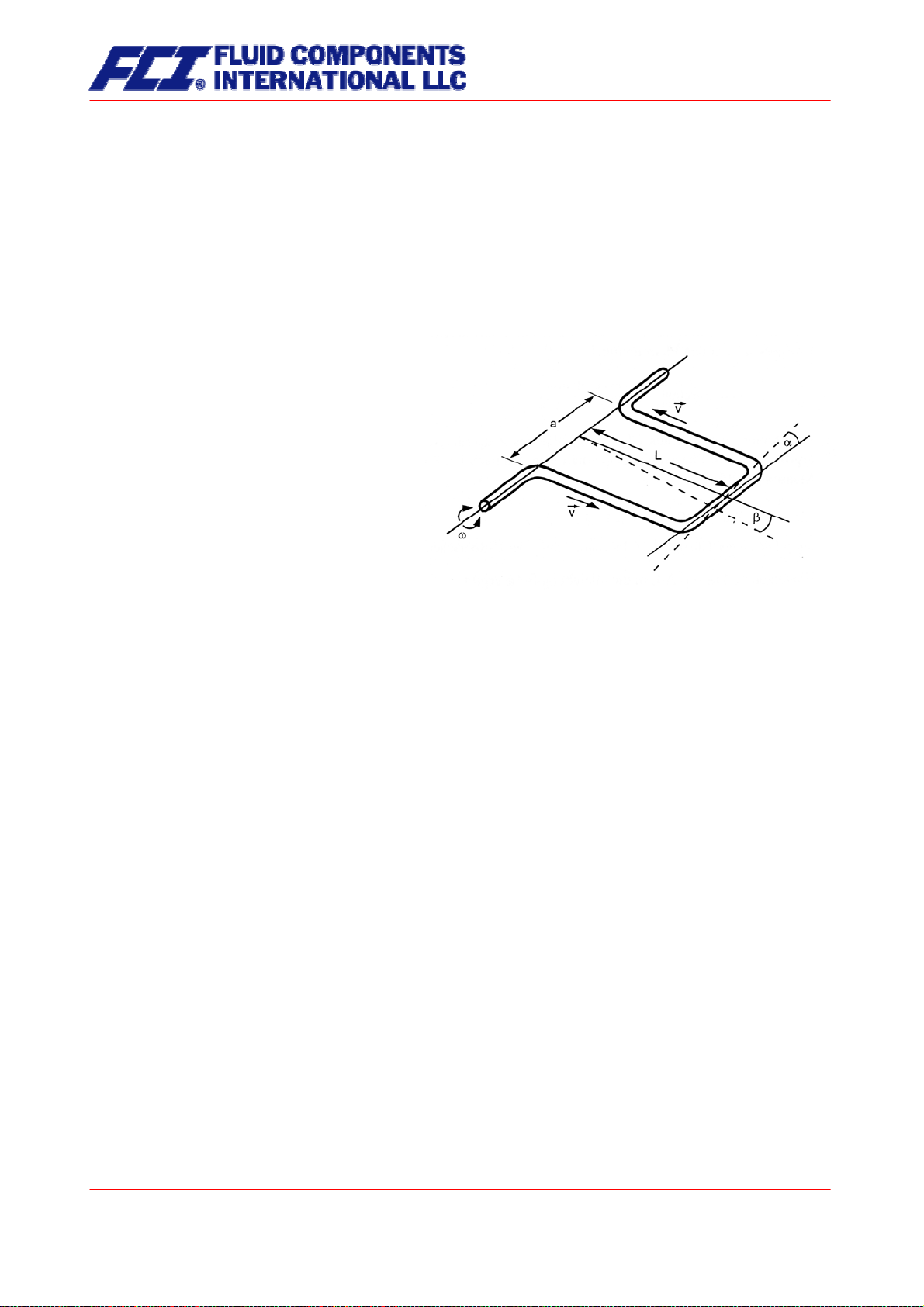
3.2.1 Measuring principle
The Coriolis mass flowmeter is based on the
principle whereby in a rotating system a force
(known as the Coriolis force) is exerted on a
mass at a rotation point that is moving towards
or away from this point.
]
2
3.2.2 System configuration
The flowmeter consists of a sensor that is mounted in a pipe, and a transmitter (see Section 5
Application domain of the CT on pp. 35), that can be directly mounted on the sensor or installed sepa-
rately (e.g. on a wall).
The transmitter oscillates the flow tubes in the sensor over a excitation coil and picks up, via the sensor
coil, the measuring signal which is proportional to the mass flow. After being temperature compensated,
the measuring signal is converted into an analog output signal that is consistent with the measuring range
setting.
C
vmF
3.2.3 Input
Measured variables: mass flow, density, temperature; volume flow is calculated
3.3 Custody transfer operations
Units designated for custody transfer operation may be certified in accordance to the local or national
ordinance. Transmitters ordered for custody transfer applications incorporate special tamper-proof software, sealed and certified, that prevents the reset of the internal totalizer.
Page 14 of 112
CMU & CT OPERATING MANUAL
Page 15

⎠
3.4 Performance characteristics of the CMU sensor
3.4.1 Reference conditions
• Established flow profile
• Inlet section has to correspond to mounting length
• Operation is to be realized in the presence of downstream control valves
• Measurement is to be realized in the absence of any gas bubbles
• Flow tubes are to be kept clean at all times
• Process temperature is to be regulated as specified in Section 3.6.1 Process temperature on
page 23
• Process pressure is to be regulated as specified in Section 3.6.6 Process pressure range on
page 23
• Ambient temperature is to range from + 10 °C to + 30 °C (50 °F to 86 °F)
• Warm-up period: 15 minutes
• Standard calibration is to be realized at 20 %, 50 % and 100 % (three times each)
• High-frequency interference is to be regulated as specified in Section 17.2 Electromagnetic
compatibility on page 110
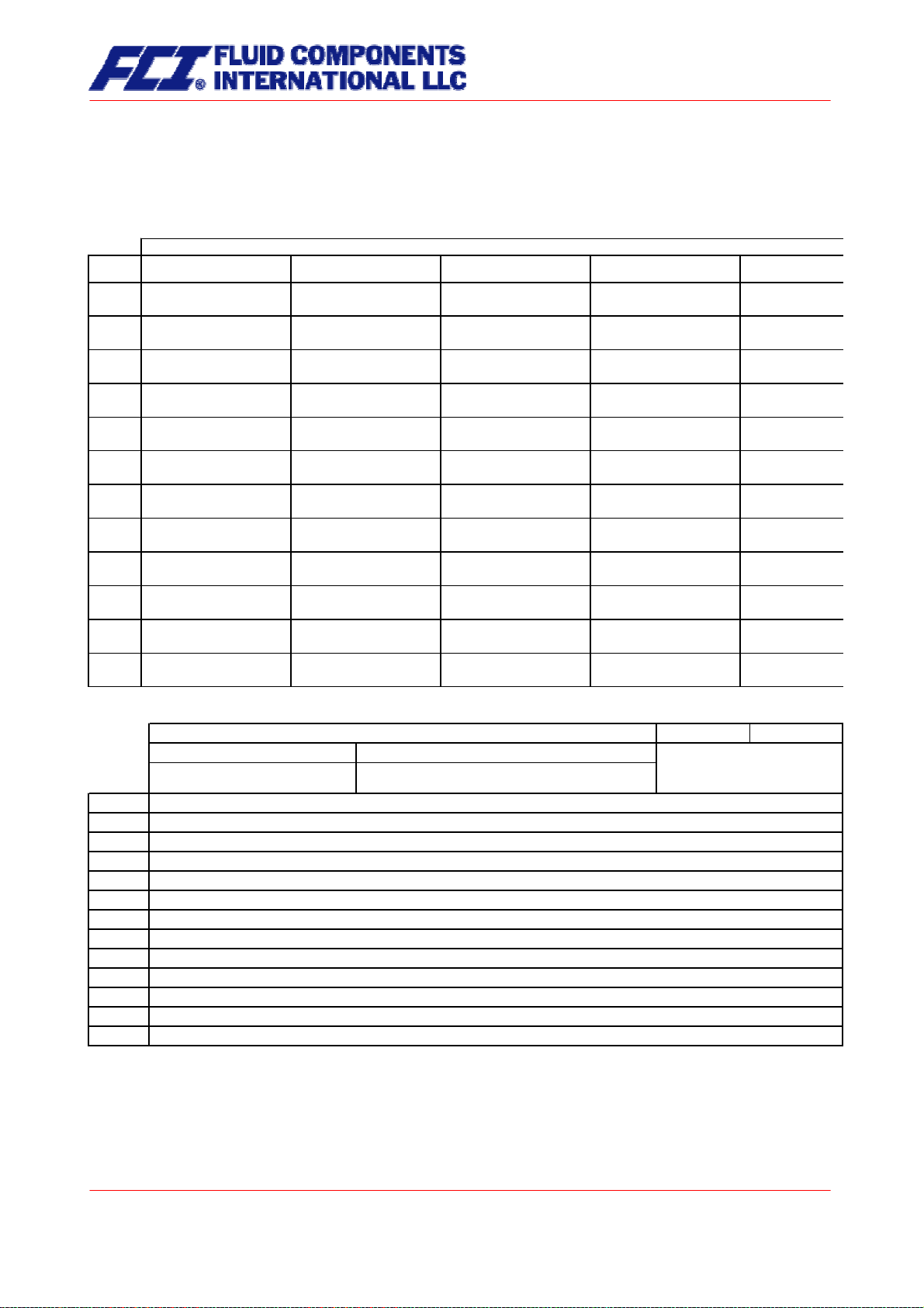
3.4.2 CMU flow ranges
Mass flow
Min.
measuring range
Model
CMU-C 60 [2.2] 600 [22.0] 330 [12.1] 0.06 [0.002]
CMU-D 250 [9.2] 2,500 [91.9] 1,150 [42.3] 0.25 [0.01]
CMU-E 1,200 [44.1] 12,000 [440.9] 5,250 [192.9] 1.2 [0.04]
CMU-G 3,000 [110.2] 30,000 [1,102.3] 20,000 [734.9] 3 [0.1]
CMU-H 6,000 [220.5] 60,000 [2,204.6] 55,000 [2,020.9] 6 [0.2]
CMU-J 20,000 [734.9] 80,000 [2,939.4] 74,000 [2,719.0] 8 [0.3]
CMU-K 25,000 [918.6] 120,000 [4,409.2] 118,000 [4,335.7] 12 [0.4]
CMU-L 30,000 [1,102.3] 200,000 [7,348.6] 200,000 [7,348.6] 20 [0.7]
CMU-N 60,000 [2,204.6] 460,000 [16,901.8] 460,000 [16,901.8] 46 [1.7]
CMU-P 150,000 [5,511.5] 700,000 [25,720.2] 700,000 [25,720.2]* 70 [2.6]
CMU-Q 300,000 [11,022.9] 1,500,000 [55,114.6] 1,350,000 [49,603.2] 150 [5.5]
CMU-R 400,000 [14,697.2] 2,200,000 [80,834.8] 1,900,000 [69,811.9] 220 [8.1]
Reference conditions: in conformity with IEC 770:
Temperature: 20 °C, relative humidity: 65 %, air pressure: 101.3 kPa
Fluid: water
kg/h [lbs/min] kg/h [lbs/min] kg/h [lbs/min] kg/h [lbs/min]
Max.
measuring range
Nominal
(¬p=1bar)
* (
Zero point stability
(of range)
p=0,6bar)
CMU & CT OPERATING MANUAL
Page 15 of 112
Part No 06EN003380 rev 1.6
Page 16

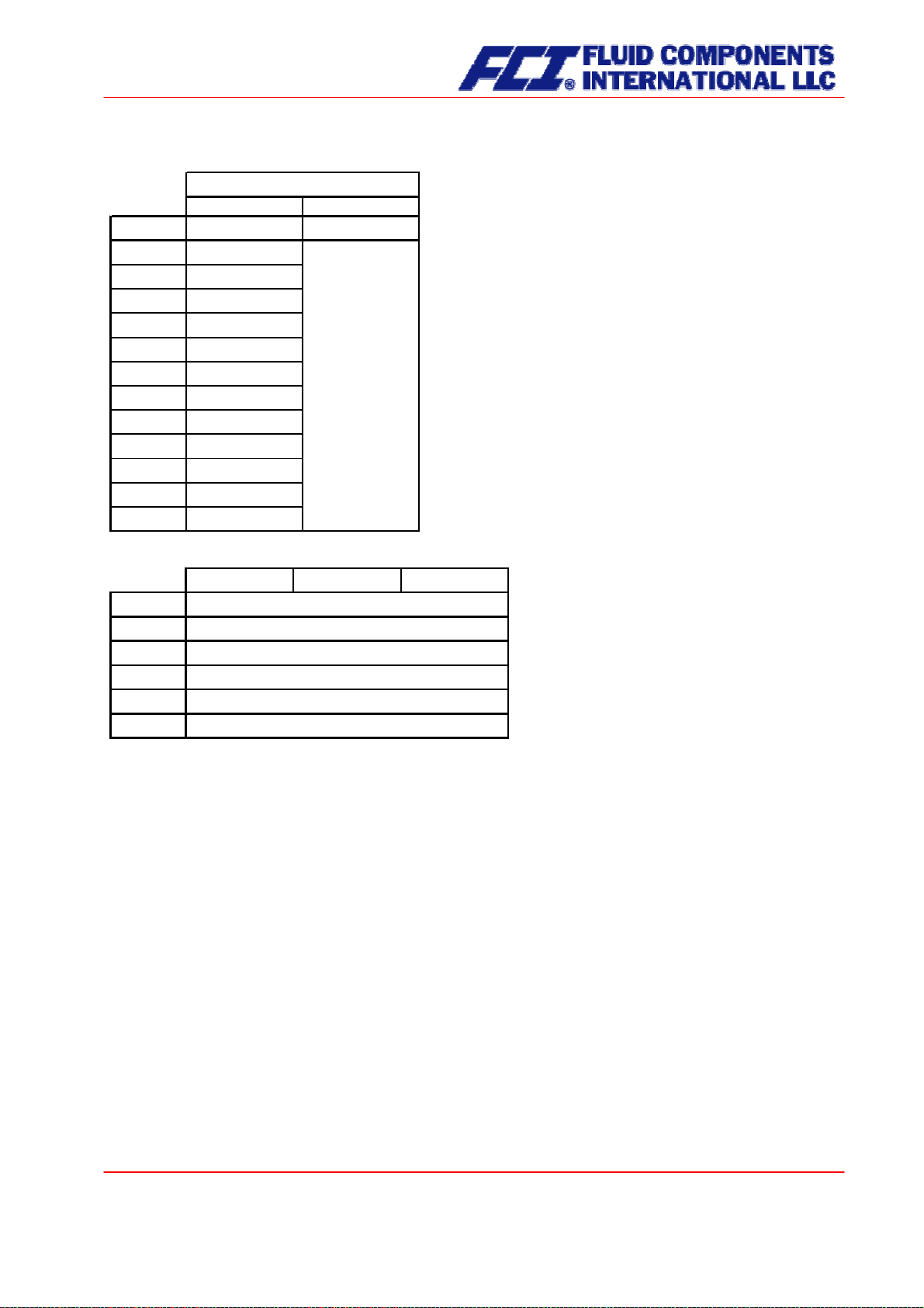
3.4.3 Density measurement
The attainable accuracy depends on the selected calibration type.
Without calibration no density measurement is possible and the empty pipe recognition
is not available!
Density accuracy
Model
CMU-C 5 g/l 2 g/l
CMU-D 5 g/l 2 g/l
CMU-E 5 g/l 1 g/l
CMU-G 5 g/l 1 g/l
CMU-H 5 g/l 1 g/l
CMU-J 5 g/l 2 g/l
CMU-K 5 g/l 2 g/l
CMU-L 5 g/l 2 g/l
CMU-N 5 g/l 2 g/l
CMU-P 5 g/l 2 g/l
CMU-Q 5 g/l 2 g/l
CMU-R 5 g/l 2 g/l
without 3-Point 5-Point
no measurement of density
3.4.4 Accuracy
Mass flow
Accuracy CMU-C to CMU-H ± 0.1% of actual flow + zero point stability (see Section 3.4.2 CMU
flow ranges)
Accuracy CMU-J to CMU-R ± 0.15% of actual flow + zero point stability (see Section 3.4.2 CMU
flow ranges)
Repeatability error ± 0.05% of actual flow (sensor with transmitter)
Additional measured values
Volume flow ± 0.2 % of actual value + zero point stability
Temperature ± 0.5 °C
Hysteresis n/a
Settling time 1 to 15 seconds
Startup drift 15 minutes
Long-term drift ± 0.02 % of upper-range value per year
Influence of ambient temperature ± 0.005 % per K
Influence of fluid temperature Compensated
Influence of fluid pressure For fluids: too small to be relevant
Page 16 of 112
CMU & CT OPERATING MANUAL
Page 17

3.4.5 Pressure loss CMU
Model
CMU-C 60 kg/h 600 kg/h
CMU-E 1200 kg/h
CMU-G
CMU-H 6000 kg/h
CMU-J 20000 kg/h
CMU-K 25000 kg/h
CMU-L 30000 kg/h
CMU-N 60000 kg/h
CMU-P 150000 kg/h
CMU-Q 300000 kg/h
CMU-R 400000 kg/h
Min.
measuring range
3000 kg/h
measuring range
12000 kg/h
30000 kg/h
60000 kg/h
80000 kg/h
120000 kg/h
200000 kg/h
460000 kg/h
700000 kg/h
1500000 kg/h
2200000 kg/h
2500 kg/hCMU-D 250 kg/h
Max.
Pressure loss [water (20°C), 1 mPas]
60 kg/h 150 kg/h 300 kg/h 450 kg/h 600 kg/h
0.05 bar 0.25 bar 0.84 bar 1.70 bar 2.82 bar
250 kg/h 625 kg/h 1250 kg/h 1875 kg/h 2500 kg/h
0.07 bar 0.35 bar 1.18 bar 2.39 bar 3.95 bar
1200 kg/h 3000 kg/h 6000 kg/h 9000 kg/h 12000 kg/h
0.07 bar 0.37 bar 1.23 bar 2.51 bar 4.15 bar
3000 kg/h 7500 kg/h 15000 kg/h 22500 kg/h 30000 kg/h
0.04 bar 0.21 bar 0.70 bar 1.43 bar 2.36 bar
6000 kg/h 15000 kg/h 30000 kg/h 45000 kg/h 60000 kg/h
0.02 bar 0.10 bar 0.32 bar 0.65 bar 1.08 bar
20000 kg/h 35000 kg/h 50000 kg/h 65000 kg/h 80000 kg/h
0.09 bar 0.25 bar 0.46 bar 0.74 bar 1.06 bar
25000 kg/h 48750 kg/h 72500 kg/h 96250 kg/h 120000 kg/h
0.06 bar 0.20 bar 0.39 bar 0.64 bar 0.95 bar
30000 kg/h 72500 kg/h 115000 kg/h 157500 kg/h 200000 kg/h
0.03 bar 0.15 bar 0.34 bar 0.58 bar 0.89 bar
60000 kg/h 160000 kg/h 260000 kg/h 360000 kg/h 460000 kg/h
0.03 bar 0.14 bar 0.33 bar 0.58 bar 0.89 bar
150000 kg/h 287500 kg/h 425000 kg/h 562500 kg/h 700000 kg/h
0.04 bar 0.13 bar 0.25 bar 0.41 bar 0.60 bar
300000 kg/h 600000 kg/h 900000 kg/h 1200000 kg/h 1500000 kg/h
0.07 bar 0.25 bar 0.51 bar 0.84 bar 1.24 bar
400000 kg/h 850000 kg/h 1300000 kg/h 1750000 kg/h 2200000 kg/h
0.06 bar 0.23 bar 0.48 bar 0.81 bar 1.21 bar
Model
CMU-C 2.2 lbs/min 22.0 lbs/min
CMU-D 9.2 lbs/min 91.9 lbs/min
CMU-G 1102.3 lbs/min110.2 lbs/min
CMU-J 734.9 lbs/min
CMU-L 1102.3 lbs/min 7348.6 lbs/min
CMU-P 5511.5 lbs/min 25720.2 lbs/min
Min.
measuring range
Max.
measuring range
440.9 lbs/minCMU-E 44.1 lbs/min
2204.6 lbs/minCMU-H 220.5 lbs/min
2939.4 lbs/min
4409.2 lbs/minCMU-K 918.6 lbs/min
16901.8 lbs/minCMU-N 2204.6 lbs/min
2.2 lbs/min 5.5 lbs/min 11.0 lbs/min 16.5 lbs/min 22.0 lbs/min
Pressure loss [water (20°C), 1 mPas]
0.73 psi 3.61 psi 12.15 psi 24.70 psi 40.87 psi
9.2 lbs/min 23.0 lbs/min 45.9 lbs/min 68.9 lbs/min 91.9 lbs/min
1.02 psi 5.07 psi 17.05 psi 34.67 psi 57.35 psi
44.1 lbs/min 110.2 lbs/min 220.5 lbs/min 330.7 lbs/min 440.9 lbs/min
1.07 psi 5.32 psi 17.91 psi 36.41 psi 60.24 psi
110.2 lbs/min 275.6 lbs/min 551.1 lbs/min 826.7 lbs/min 1102.3 lbs/min
0.61 psi 3.02 psi 10.17 psi 20.68 psi 34.21 psi
220.5 lbs/min 551.1 lbs/min 1102.3 lbs/min 1653.4 lbs/min 2204.6 lbs/min
0.28 psi 1.39 psi 4.67 psi 9.49 psi 15.69 psi
734.9 lbs/min 1286.0 lbs/min 1837.2 lbs/min 2388.3 lbs/min 2939.4 lbs/min
1.36 psi 3.61 psi 6.74 psi 10.67 psi 15.35 psi
918.6 lbs/min 1791.2 lbs/min 2663.9 lbs/min 3536.5 lbs/min 4409.2 lbs/min
0.88 psi 2.84 psi 5.69 psi 9.34 psi 13.74 psi
1102.3 lbs/min 2663.9 lbs/min 4225.5 lbs/min 5787.0 lbs/min 7348.6 lbs/min
0.47 psi 2.18 psi 4.89 psi 8.48 psi 12.88 psi
2204.6 lbs/min 5878.9 lbs/min 9553.2 lbs/min 13227.5 lbs/min 16901.8 lbs/min
0.36 psi 2.03 psi 4.75 psi 8.39 psi 12.88 psi
5511.5 lbs/min 10563.6 lbs/min 15615.8 lbs/min 20668.0 lbs/min 25720.2 lbs/min
0.59 psi 1.83 psi 3.62 psi 5.92 psi 8.68 psi
CMU & CT OPERATING MANUAL
Page 17 of 112
Part No 06EN003380 rev 1.6
Page 18

A
3.4.6 Ambient temperature
− 40 °C to + 60 °C (-40 °F to 140 °F)
3.4.7 Ambient temperature range
− 40 °C to + 60 °C (-40 °F to 140 °F); a special cable is required for temperatures below − 20 °C (-4 °F)
3.4.8 Storage temperature
− 25 °C to + 60 °C (-13 °F to 140 °F), − 40 °C (-40°F) available as special version
3.4.9 Climatic category
In conformity with IEC 654-1. Unsheltered class D locations with direct open-air climate.
3.4.10 Ingress protection
Standard version: IP 66 (NEMA 6); special version IP 68 (NEMA 6P) DIN EN 60529, if suitable and tightly
screwed down cable glands are used.
3.5 Operating conditions
3.5.1 Installation
The sensor is to be protected, wherever possible, against valves, manifolds and similar fittings that generate turbulence. The sensor is to be installed in accordance with the following instructions.
Diagram showing flowmeter installation
BC C C
Flowmeter installation: A = sensor, B = valve, C = pipe clamps and supports
Under no circumstances is the
sensor to be used to support a
pipe.
C
Page 18 of 112
CMU & CT OPERATING MANUAL
Page 19

Do not install the sensor in suspended pipes.
3.5.2 Installation positions
Standard installation position
Do not adjust the position of a
pipe by pulling or grasping the
sensor.
Installation position A
Installation position B
CMU & CT OPERATING MANUAL
Page 19 of 112
Part No 06EN003380 rev 1.6
Page 20

Installation position C
3.5.3 Assessment of installation position
Type of fluid Position Assessment
Pure liquids Standard installation
Self-draining flow tubes
position
Position A or B OK
Position C Liquid residue remains in pipe
Liquids with gas bub-
bles
Standard installation
position
Self-draining flow tubes, gas bubbles do not accumulate
in flowmeter
Position A Not recommended owing to gas bubble accumulation in
flowmeter
Position B Gas bubbles may accumulate in the presence of low flow
velocities
Position C No gas bubble accumulation in flowmeter, liquid residues
may remain in device after discharge
Liquids containing
substances that could
Standard installation
position
Self-draining flow tubes, no deposit formation
form deposits
Position A OK
Position B Substances in the liquid could form deposits at low flow
velocities
Position C Not recommended owing to presence in flowmeter of
substances that could form deposits
Liquids containing
gas bubbles, as well
Standard installation
position
Self-draining flow tubes, no accumulation of gases or
substances that could form deposits
as gas bubbles containing substances
that could form deposits
Position A Not recommended owing to gas bubble accumulation in
flowmeter
Position B Gas bubbles or substances that could form deposits at
low flow velocities
Position C Not recommended owing to presence in flowmeter of
substances that could form deposits
Gases that do not
form a condensate
Standard installation
position,
Any of these installations positions can be used
Position A, B or C
Page 20 of 112
CMU & CT OPERATING MANUAL
Page 21

Type of fluid Position Assessment
Gas, condensateforming gas/liquid,
Standard installation
position
Flow direction should be from top to bottom so that any
condensate that forms can flow out efficiently
moisture
Position A OK
Position B Condensate might form in flowmeter
Position C Not recommended owing to condensate accumulation in
flowmeter
Slurries Standard installation
Optimal installation position
position
Position A High density substances could accumulate in the flow-
meter
Position B Gas bubbles could accumulate
Position C Gas bubbles or high density substances could accumu-
late in the flowmeter
3.5.4 Pressure surges
Pressure surges in a pipe could be provoked by a sudden decrease in flow caused by rapid closing of a
valve or similar factors. This change in pressure can lead to underpressure downstream from a valve that
has been closed rapidly, and to outgasing. If the valve is mounted directly on the inlet section of the
flowmeter, a gas bubble can form in the flow tube that can cause a measuring signal disturbance that
would shift the zero point of the output signal. In extreme cases, a pressure surge could cause mechanical damage to the sensors and/or flow tube.
Whenever possible, quick-closing valves should be mounted downstream from the sensor. If this is not
feasible, such valves are to be mounted a minimum of 10 x DIA (Φ) from the nearest sensor. Alternatively, valve closing speed can be reduced.
3.5.5 Using the device with hazardous fluids
The sealing technology used in the standard CMU mass flowmeter renders the device unsuitable for use
with hazardous fluids. Only sensors that meet the standards for safety instruments are suitable for use
with hazardous fluids.
The pathway between the sensor and transmitter must be pressure-tight so as to prevent fluid from leaking out of a sensor in the event a sensor develops a defect.
In the case of welded components, a colored liquid penetration test should be performed on the welds, or
one joint (only the first one) should be x-rayed. Alternatively, an internal pressure monitoring device can
be used to detect any defect.
3.5.6 Vibration stability
The sensors are insensitive to vibration; vibration stability has been validated in accordance with
DIN IEC 68-2-6, for up to 1 g at 10 to 150 Hz.
If pipe vibration is greater than 1 g in the 10-150 Hz range, an additional fastening is to be mounted as
shown in the following drawings. This fastening will prevent vibration from affecting the device’s mechanical configuration and/or measurement readings. The following drawings are valid for a sensor with a
nominal size of approximately 2 inches [DN 040]. Installation is to be realized as shown in this drawing.
CMU & CT OPERATING MANUAL
Page 21 of 112
Part No 06EN003380 rev 1.6
Page 22
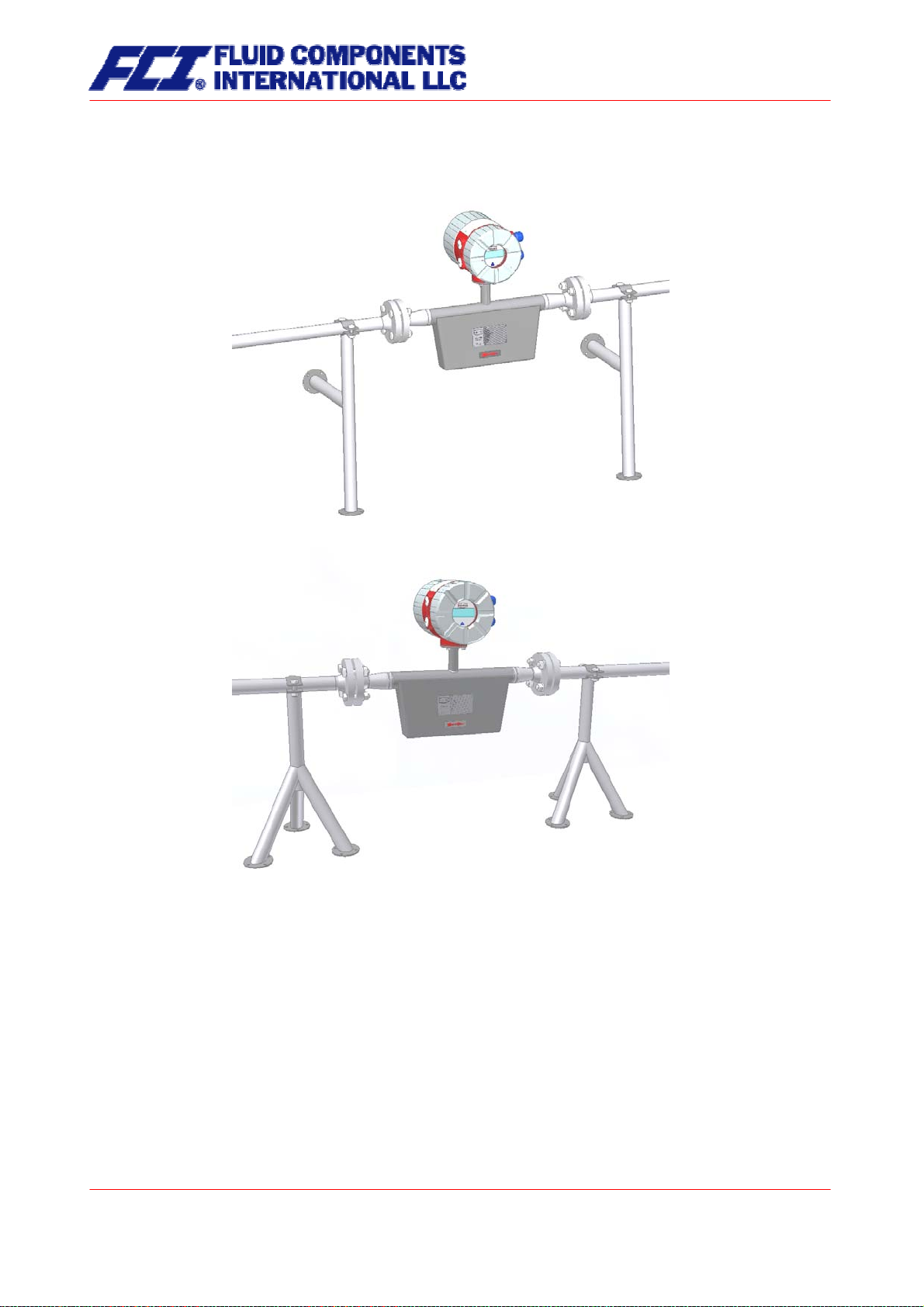
Installation using wall supports
Foot-mounted installation
Page 22 of 112
CMU & CT OPERATING MANUAL
Page 23

3.6 Process conditions
3.6.1 Process temperature
− 40 °C to + 260 °C (-40 °F to 500 °F); rating plate range must be observed
3.6.2 Physical state
Liquid product (maximum density 2 kg/l)
Gaseous product (minimum density 0.002 kg/l in operating state)
3.6.3 Viscosity
0.3 up to 50,000 mPas (0.3 to 50,000 cP)
3.6.4 Gas content
The use of products containing gas is not allowed for custody transfer operations. In other applications,
the presence of gas will increase false readings. In order for the readings of products containing gas to
be valid, small gas bubbles must be homogeneously distributed in the fluid. Large gas bubbles will automatically provoke extremely false readings and will shift the zero point. Thus, the extent to which readings
are false is determined by the process conditions. A rule of thumb in this regard is as follows: A 1 % gas
component will increase false readings by 1 %. The gas component is not to exceed 5 %.
3.6.5 Process temperature range
+ 260 °C (500 °F)
3.6.6 Process pressure range
According to PN16 pressure rating: 232 psig [16 bar] and PN40: 580 psig [40 bar]
3.6.7 Outlet pressure
Outlet pressure must be greater than the vapor pressure Ps (static pressure) of the measured product.
3.7 Connection to the transmitter
3.7.1 Integral mount configuration
When the transmitter is mounted directly on the sensor, no cable connection between the two components is needed. This connection is integrated at the factory.
3.7.2 Remote mount configuration
If the transmitter is
dards are to be adhered to. The maximum cable length is 300 m (1000ft). See Section 11.5.2 Wiring diagram on page 46 for information regarding the connection and cable specifications.
not mounted directly on the sensor, installation regulations and applicable legal stan-
CMU & CT OPERATING MANUAL
Page 23 of 112
Part No 06EN003380 rev 1.6
Page 24
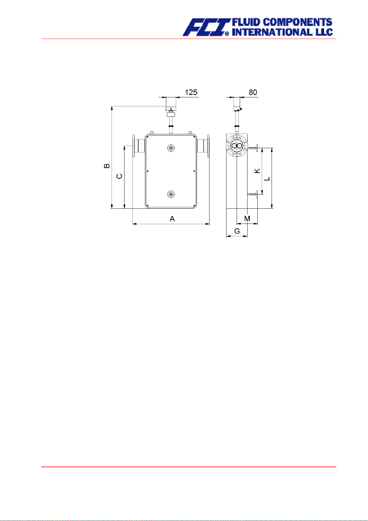
3.8 Construction details
3.8.1 Dimensions and weight
Standard versions:
End
Model
CMU-C SW10 --
connection inch [mm]
connection inch [mm]
End
SW12 --
End
connection inch [mm]
DN10 [360]14.2
A
End
connection inch [mm]
End
connection inch
½" NPT (f)¼" NPT (f) [300]11.8
11.8
CMU-D
CMU-E ½" NPT (f) --
CMU-G - --
CMU-H
CMU-J
CMU-K
CMU-L
CMU-N
CMU-P
CMU-Q
CMU-R
SW12 -
---
---
DN40 [1,018]40.1
DN50 [1,176]46.3
DN80 [1,370]53.9
DN100 [1,726]68.0
DN150 [2,184]86.0
DN250 [2,913]114.7
-
DN15 [515]20.3
DN25 [632]24.9
DN40
DN50 [1,024]40.3
DN80
DN100 [1,358]53.5
DN150
DN200 [2,198]86.5
DN300
[770]30.3
[1,196]47.1
[1,732]68.2
[2,284]89.9 DN300 [1,900]DN200 [2,268]89.3 DN250
[2,925]115.2
DN15 [396]15.615.4 [390]DN10
DN25 [520]20.5
DN40 25.3 [642] ¾" 150lb 25.9 [657] 1" 150lb 26.1
DN50 [776]30.6
DN80 [1,044]41.1
DN100 [1,184]46.6
DN150 [1,090]42.9
DN200
DN300 [1,864]73.4
DN350 [2,933]115.5
[1,448]57.0
74.8
½" NPT (f) [300]11.8
- - - 1½" 150lb 31.7
1½" 150lb 41.3 [1,050] 2" 150lb 41.5
2" 150lb 47.5 [1,207] 3" 150lb 48.0
3" 150lb 54.6 [1,388] 4" 150lb 55.1
4" 150lb 69.7 [1,770] 6" 150lb 70.7
6" 150lb 88.6 [2,250] 8" 150lb 89.4
8" 150lb 92.4 [2,348] 10" 150lb 92.4
10" 150lb 117.2 [2,976] 12" 150lb 117.9
½" 150lb 16.4
½" 150lb 21.1
B
Integral mount transmitter Remote mount transmitter
-40°C - 260°C
(-40°F to 500°F)
Model
-40°C - 100°C
(-40°F to 212°F)
-40°C - 150°C
(-40°F to 302°F)
-40°C - 100°C
(-40°F to 212°F)
-40°C - 180°C
(-40°F to 356°F)
inch [mm] inch [mm] inch [mm] inch [mm] inch [mm] inch [mm] inch [mm]
CMU-C 12.9 [328] 16.9 [430] 8.9 [225] 12.9 [327] 16.8 [427] 3.3 [85] 1.6 [40]
CMU-D 13.5 [343] 17.5 [445] 9.4 [240] 13.5 [342] 17.4 [442] 3.9 [100] 1.6 [40]
CMU-E 15.6 [395] 19.6 [497] 11.5 [292] 15.5 [394] 19.4 [494] 5.8 [148] 1.9 [48]
CMU-G 18.1 [460] 22.1 [562] 14.1 [357] 18.1 [459] 22.0 [559] 7.9 [200] 2.9 [74]
CMU-H 20.8 [528] 24.8 [630] 16.7 [425] 20.7 [527] 24.7 [627] 10.0 [255] 4.0 [101]
CMU-J 39.8 [1,010] 43.8 [1,112] 35.7 [907] 39.7 [1,009] 43.7 [1,109] 24.2 [615] 9.1 [230]
CMU-K 47.6 [1,210] 51.7 [1,312] 43.6 [1,107] 47.6 [1,209] 51.5 [1,309] 31.5 [800] 9.8 [250]
CMU-L 48.4 [1,230] 52.4 [1,332] 44.4 [1,127] 48.4 [1,229] 52.3 [1,329] 32.1 [815] 10.6 [270]
CMU-N 61.4 [1,560] 65.4 [1,662] 57.4 [1,457] 61.4 [1,559] 65.3 [1,659] 42.1 [1,070] 15.0 [380]
CMU-P 67.7 [1,720] 71.7 [1,822] 63.7 [1,617] 67.7 [1,719] 71.6 [1,819] 47.6 [1,210] 15.7 [400]
CMU-Q 73.2 [1,860] 77.2 [1,962] 69.2 [1,757] 73.2 [1,859] 77.1 [1,959] 51.2 [1,300] 21.7 [550]
CMU-R 73.4 [1,865] 77.4 [1,967] 69.4 [1,762] 73.4 [1,864] 77.3 [1,964] 55.1 [1,400] 20.1 [510]
C
G
Page 24 of 112
CMU & CT OPERATING MANUAL
Page 25
Weight:
Weight
Sensor Transmitter
Model
CMU-C 3.5 [7.7]
CMU-D 4 [8.8]
CMU-E 7 [15.4]
CMU-G 15 [33.1]
CMU-H 29 [63.9]
CMU-J 140 [308.6] 4.5 [9.9]
CMU-K 200 [440.9]
CMU-L 250 [551.2]
CMU-N 470 [1036.2]
CMU-P 750 [1653.5]
CMU-Q 850 [1873.9]
CMU-R 900 [1984.1]
Heated versions:
kg [lbs] kg [lbs]
KLM
Model
inch [mm] inch [mm] inch [mm]
CMU-J 24.0 [610] 26.8 [680] 9.4 [240]
CMU-K 31.5 [800] 34.4 [875] 9.8 [250]
CMU-L 23.6 [600] 30.9 [785] 10.6 [270]
CMU-N 42.5 [1080] 46.9 [1190] 12.8 [325]
CMU-P 47.2 [1200] 52.4 [1330] 13.2 [335]
CMU & CT OPERATING MANUAL
Part No 06EN003380 rev 1.6
Page 25 of 112
Page 26
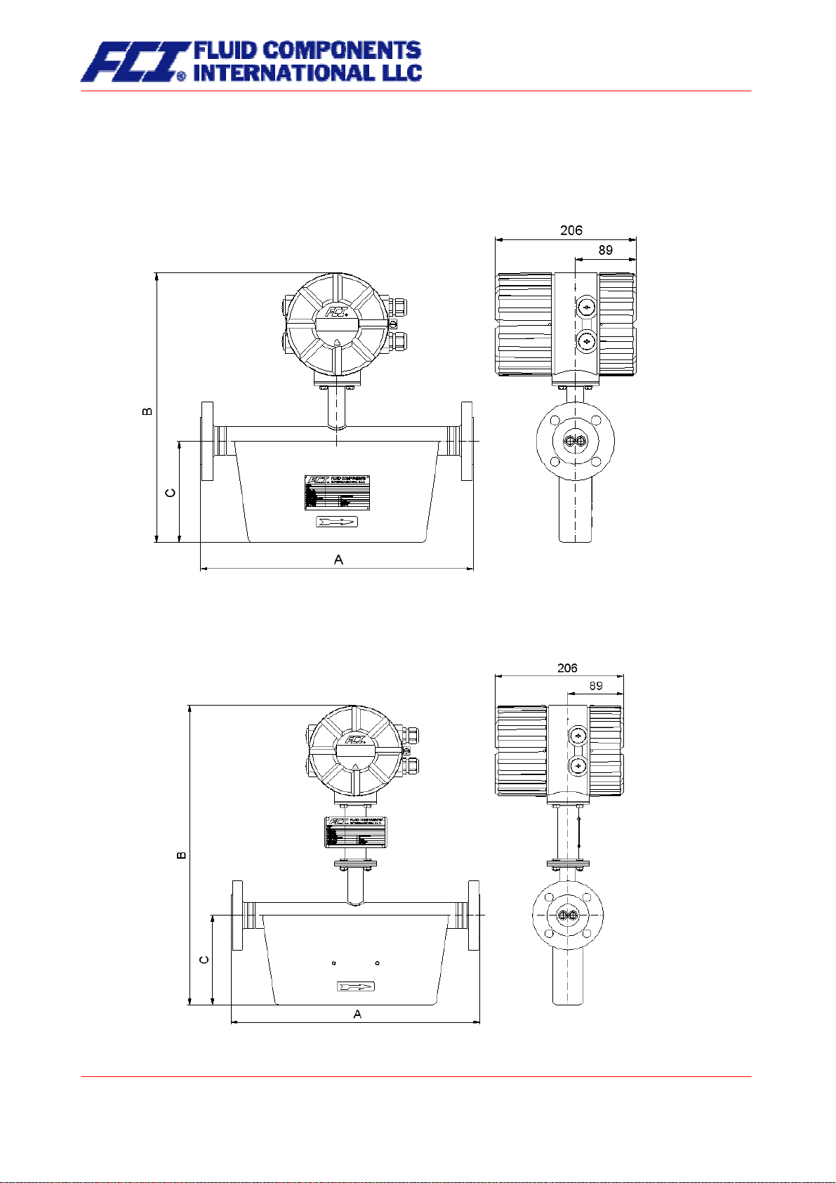
3.8.2 Dimension drawing for the types CMU-C to CMU-H
3.8.2.1 Standard version dimension drawing
Integral mount configuration that is suitable for process temperatures up to 100 °C (212°F):
For all the dimensions and weight, see Section 3.8.1 Dimensions and weight on page 24.
3.8.2.2 Integral mount version up to 150 °C (302 °F)
Integral mount configuration that is suitable for process temperatures up to 150 °C (302°F):
For all the dimensions and weights, see Section 3.8.1 Dimensions and weight on page 24.
Page 26 of 112
CMU & CT OPERATING MANUAL
Page 27
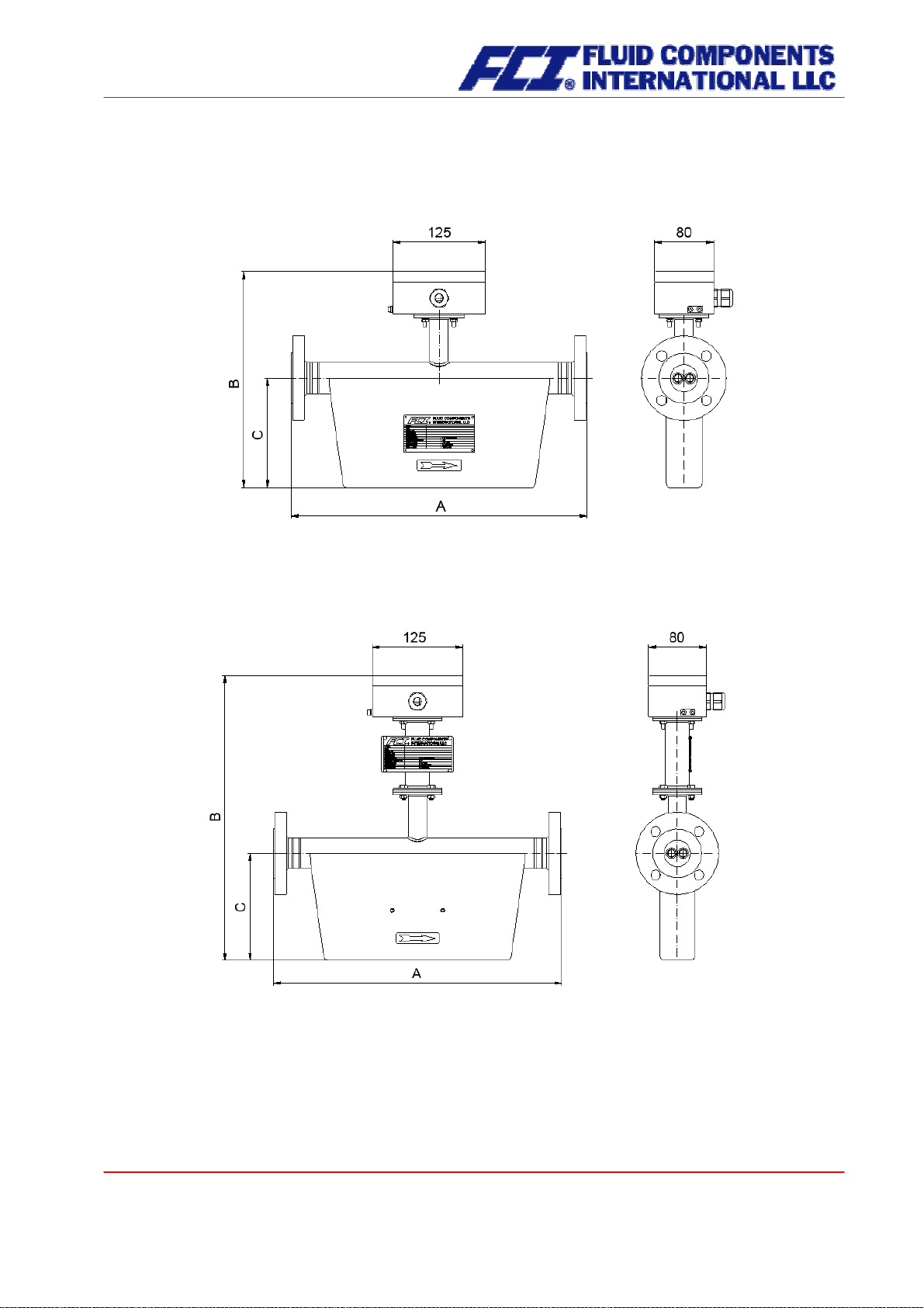
3.8.2.3 Remote mount version dimension drawing
Remote mount configuration with junction box that is suitable for process temperatures up to 100 °C
(212 °F):
For all the dimensions and weights, see Section 3.8.1 Dimensions and weight on page 24.
3.8.2.4 Remote mount version dimension drawing up to 180 °C (356 °F)
Remote mount configuration with junction box that is suitable for process temperatures up to 180 °C
(356 °F):
For all the dimensions and weights, see Section 3.8.1 Dimensions and weight on page 24.
CMU & CT OPERATING MANUAL
Part No 06EN003380 rev 1.6
Page 27 of 112
Page 28
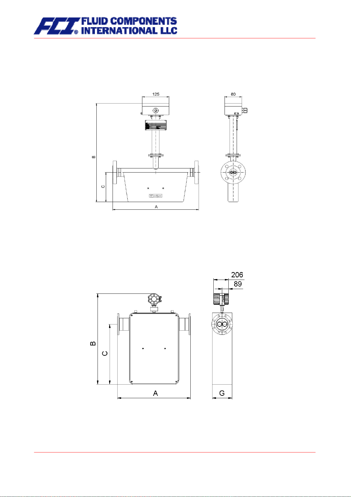
3.8.2.5 Remote mount version dimension drawing up to 260 °C (500 °F)
Remote mount configuration with junction box that is suitable for process temperatures up to 260 °C
(500 °F):
For all the dimensions and weights, see Section 3.8.1 Dimensions and weight on page 24.
3.8.3 Dimension drawing for the types CMU-J to CMU-R
3.8.3.1 Standard version dimension drawing
Integral mount configuration that is suitable for process temperatures up to 100 °C (212 °C):
For all the dimensions and weights, see Section 3.8.1 Dimensions and weight on page 24.
Page 28 of 112
CMU & CT OPERATING MANUAL
Page 29

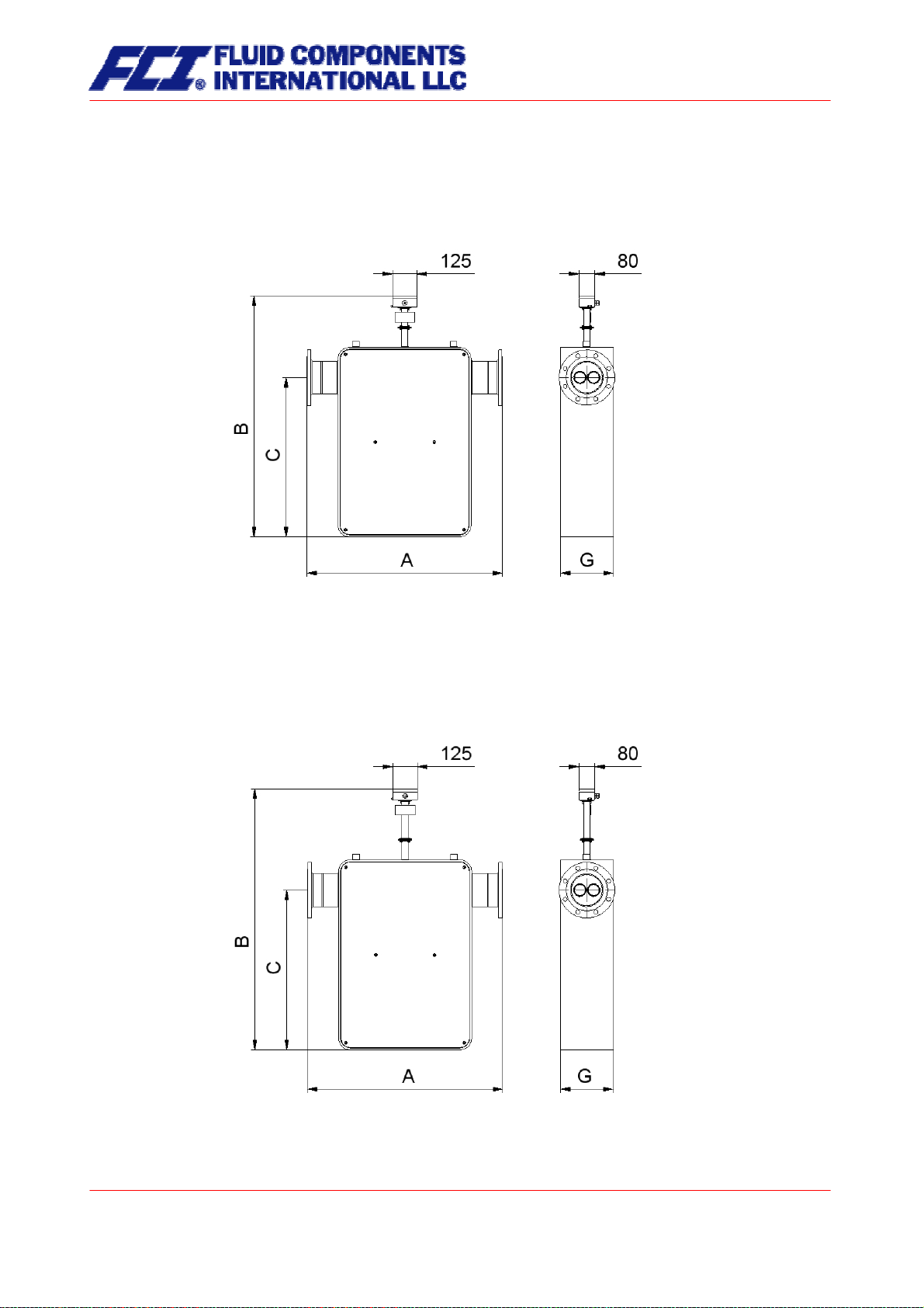
3.8.3.2 Integral mount configuration up to 180 °C (356°F)
Integral mount configuration that is suitable for process temperatures up to 180 °C (356 °F):
For the dimensions and weights, see Section 3.8.1 Dimensions and weight on page 24.
3.8.3.3 Remote mount version dimension drawing
Remote mount configuration (with junction box) that is suitable for process temperature up to 100 °C
(212 °F):
For the dimensions and weights, see Section 3.8.1 Dimensions and weight on page 24.
CMU & CT OPERATING MANUAL
Part No 06EN003380 rev 1.6
Page 29 of 112
Page 30
3.8.3.4 Remote mount version dimension drawing up to 180 °C (356°F)
Remote mount configuration (with junction box) that is suitable for process temperatures up to 180 °C
(356°F):
For the dimensions and weights, see Section 3.8.1 Dimensions and weight on page 24.
3.8.3.5 Remote mount version up to 260 °C (500°F)
Remote mount configuration (with junction box) that is suitable for process temperatures up 260 °C
(500 °F):
For all the dimensions and weights, see Section 3.8.1 Dimensions and weight on page 24
Page 30 of 112
CMU & CT OPERATING MANUAL
Page 31

3.8.4 Heater dimension drawings for CMU-J up to CMU-R
3.8.4.1 Heater for standard version
Integral mount configuration that is suitable for process temperatures up to 100 °C (212°F):
For all the dimensions and weights, see Section 3.8.1 Dimensions and weight on page 24.
3.8.4.2 Heater for integral mount version up to 150 °C (302°F)
Integral mount configuration that is suitable for process temperatures up to 150 °C (302°F):
For the dimensions and weights, see Section 3.8.1 Dimensions and weight on page 24.
CMU & CT OPERATING MANUAL
Part No 06EN003380 rev 1.6
Page 31 of 112
Page 32

3.8.4.3 Heater for remote mount version
Remote mount configuration (with junction box) that is suitable for process temperatures up to 100 °C
(212 °F):
For the dimensions and weights, see Section 3.8.1 Dimensions and weight on page 24.
3.8.4.4 Heater for remote mount version up to 180 °C (356°F)
Remote mount configuration (with junction box) that is suitable for process temperatures up to 180 °C
(356 °F):
For the dimensions and weights, see Section 3.8.1 Dimensions and weight on page 24.
Page 32 of 112
CMU & CT OPERATING MANUAL
Page 33
3.8.4.5 Heater for remote mount version up to 260 °C (500 °F)
Remote mount configuration (with junction box) that is suitable for process temperatures up to 260 °C
(500 °F):
For the dimensions and weights, see Section 3.8.1 Dimensions and weight on page 24.
3.8.5 Material
Sensor housing
CMU up to 1.5 inch [DN040]: 1.4301 (304L)
CMU starting from 2 inch [DN050]: epoxy painted carbon steel, 1.4301 (304L) is available as
an option
Flow tubes:
Splitter:
Sealing strip and/or flange:
1.4404 (316L)
1.4571 (316Ti)
Hastelloy
Tantalum
Other materials on request
CMU & CT OPERATING MANUAL
Part No 06EN003380 rev 1.6
Page 33 of 112
Page 34

3.9 Sensor CMU approvals
3.9.1 Explosion protection
• Intrinsically safe sensor circuits
• BVS 05 ATEX E 145 X
• II 1/2G EEx ia IIC T6 – T2
• (Zone 0 permissible in flow tube)
The explosion protection approvals are available on our website
3.9.2 CE marking
• Pressure Equipment Directive 97/23/EC
• Explosion Protection Directive 94/9/EC
3.9.3 Custody transfer operations
The declarations of conformity certifying FCI flowmeters for custody transfer operations are available
upon request from the FCI factory.
upon request from the FCI factory.
4. Commissioning
4.1 Zero point calibration
In order to ensure that precise measurements are obtained, zero point calibration is to be realized the
first time the device is put into operation
calibration is to be carried out using a fluid.
The zero calibration procedure is as follows:
• Install the sensor as described in the manufacturer’s instructions.
• Check to ensure that the sensor is completely filled with fluid and that there are no gas bub-
bles in the flow tubes.
• Define the process conditions such as pressure, temperature and density.
• Close a potential shut-off device behind the sensor.
• Operate the transmitter in accordance with the instructions in Section 13.4.4 Zero point cali-
bration on page 66.
• Make sure that sufficient time is allowed for the electronics to warm up.
• Allowing fluid to flow through the sensor during the zero calibration procedure will skew the
zero point and result in false readings.
4.2 Startup conditions
The device is not subject to specific startup conditions. However, pressure surges should be avoided.
and before any regular operations are carried out. Zero point
Page 34 of 112
CMU & CT OPERATING MANUAL
Page 35

5. Application domain of the CT transmitter
The microprocessor controlled CT transmitter (referred to as CT) for use with CMM, CMB and CMU sensors is a programmable transmitter that processes measurement data and displays and transmits various
types of measurement results.
The CT is communication enabled and supports both the HART
can be customized using control unit BE2. Although basic configuration settings such as transmitter calibration are realized at the factory, other settings such as those for measurement data processing, analysis, display and output are user definable.
User settings are protected by a user definable password.
Settings that are essential for proper operation of the transmitter in conjunction with the sensor (e.g. calibration and initialization values) are accessible only to service technicians via a password that is not provided to customers.
®
protocol and Profibus-PA. The device
6. CT transmitter: mode of operation and configuration
6.1 Measuring principle
The Coriolis mass flowmeter is based on the principle whereby in a rotating system a force (known as
Coriolis force) is exerted on a mass at a rotation point that is moving towards or away from this point. By
configuring the sensor in a specific fashion, this force can be used to measure mass flow directly. The CT
transmitter evaluates the sensor signal (see Section 3.2.1 Measuring principle on page 14).
CMU & CT OPERATING MANUAL
Part No 06EN003380 rev 1.6
Page 35 of 112
Page 36

6.2 System configuration
Transmitter:
The CT transmitter regulates the excitation of the sensor vibration system and processes the sensor signals. The standard model is equipped with two analog 0/4 to 20 mA outputs, an impulse or frequency
output and a status output, and is enabled for digital data transfer via the HART
also available with a Profibus-PA field bus.
Sensor:
The CMM, CMB and CMU sensors measure flow, density and temperature in fluids. The device can be
used to perform measurements with any liquid or gaseous product providing that the sensor material is
suitable for the product being used.
6.2.1 DSB data memory module
The replaceable plug and play memory module is mounted on a printed board and stores all sensor data
such as sensor constants, model numbers, serial numbers, and so on. Consequently, the memory module is linked to the sensor and is attached to the transmitter housing with a nylon cord.
If the transmitter is replaced, the memory module should be transferred to the new transmitter. When the
flowmeter is started up, the device continues using the values stored in the memory module. Thus, the
DSB memory module provides maximum safety and comfort when device components are replaced.
Electronics compartment, CPU board UMC3-30
DSB slot
®
protocol. The device is
Page 36 of 112
CMU & CT OPERATING MANUAL
Page 37

7. Input
7.1 Measured variable
Mass flow rate, temperature, density and volume flow (calculated from the preceding measured variables).
7.2 Measuring range
The measuring range, which varies according to which sensor (CMM, CMB or CMU) is used, can be
found on the relevant data sheet or rating plate (see Section 3.4.2 CMU flow ranges on page 15).
CMU & CT OPERATING MANUAL
Part No 06EN003380 rev 1.6
Page 37 of 112
Page 38

8. Output
8.1 Output signal
All signal outputs Electrically isolated from each other and from ground
Analog outputs 2 x 0/4 to 20 mA active( EEx “i” [outputs i.s.] or EEx “e”)
Current output 1:
Mass flow, volume flow, density, temperature
(when using the HART
flow)
Current output 2:
Mass flow, volume flow, density, temperature
Pulse output Pulse duration: default value 50 ms
(Binary output 1) Pulse duration: adjustable range is 10 to 2000 ms
Mark-to-space ratio is 1:1 if the set pulse duration is not reached.
As a frequency output 1 kHz (optionally 10 kHz)
Passive, via optocoupler
= 30 V
U
i
= 200 mA
I
i
= 3 W
P
i
The CT binary output 1 can be wired as a passive or an active output by inserting the JP10 plug-in jumpers on the UMC3-10 PCB
accordingly. For the active output, the jumpers BR11 and BR12
must be closed in addition.
Pulse value 1 pulse/unit
The pulse value can be multiplied by a factor between 0.01 and
100.0 (decade increments) of the selected pulse unit, e.g. lbs, kg,
m³...
Status output For: forward and reverse flow, MIN flow rate, MAX flow rate (Binary
output 2): MIN density, MAX density, MIN temperature, MAX temperature, alarm
Second pulse output (out of phase by 90°)
Passive via optocoupler
= 30 V
U
i
= 200 mA
I
i
= 3 W
P
i
®
protocol, output 1 is assigned to mass
Active, potential-free
(24 V =; max. 20 mA)
8.2 Failure signal
A failure in the meter can be indicated via the current outputs or the status output. The current outputs
can be set to a failure signal (alarm) of I < 3.8 mA or I > 22 mA. The status output can be configured as
make or brake contact.
Page 38 of 112
CMU & CT OPERATING MANUAL
Page 39

8.3 Load
Standard version: ≤ 500 ohms
Explosion-proof version:
®
HART
minimum load: > 250 ohms
≤ 500 ohms
8.4 Damping
Programmable from 0 to 60 seconds
8.5 Low flow cutoff
The low flow cutoff can be set to values between 0 and 20% using the software. The set value refers to
the upper-range value. If the measured value is lower than the set volume, the flow rate will set to 0.0
(lb/m, kg/h). This results in the analog output being set to 0/4 mA, and the pulse output will stop generating pulses.
9. CT performance characteristics
9.1 Reference conditions
In conformity with IEC 770
Temperature: 20 °C (68 °F), relative humidity: 65 %, air pressure: 101.3 kPa (14.7 psi)
9.2 Measured error
Measured error and zero point stability see sensor data sheet or Section 3.4.2 CMU flow ranges on
page 15.
9.3 Repeatability error
± 0.05 % of actual value (sensor with transmitter)
9.4 Influence of ambient temperature
± 0.05 % per 10 K
CMU & CT OPERATING MANUAL
Part No 06EN003380 rev 1.6
Page 39 of 112
Page 40
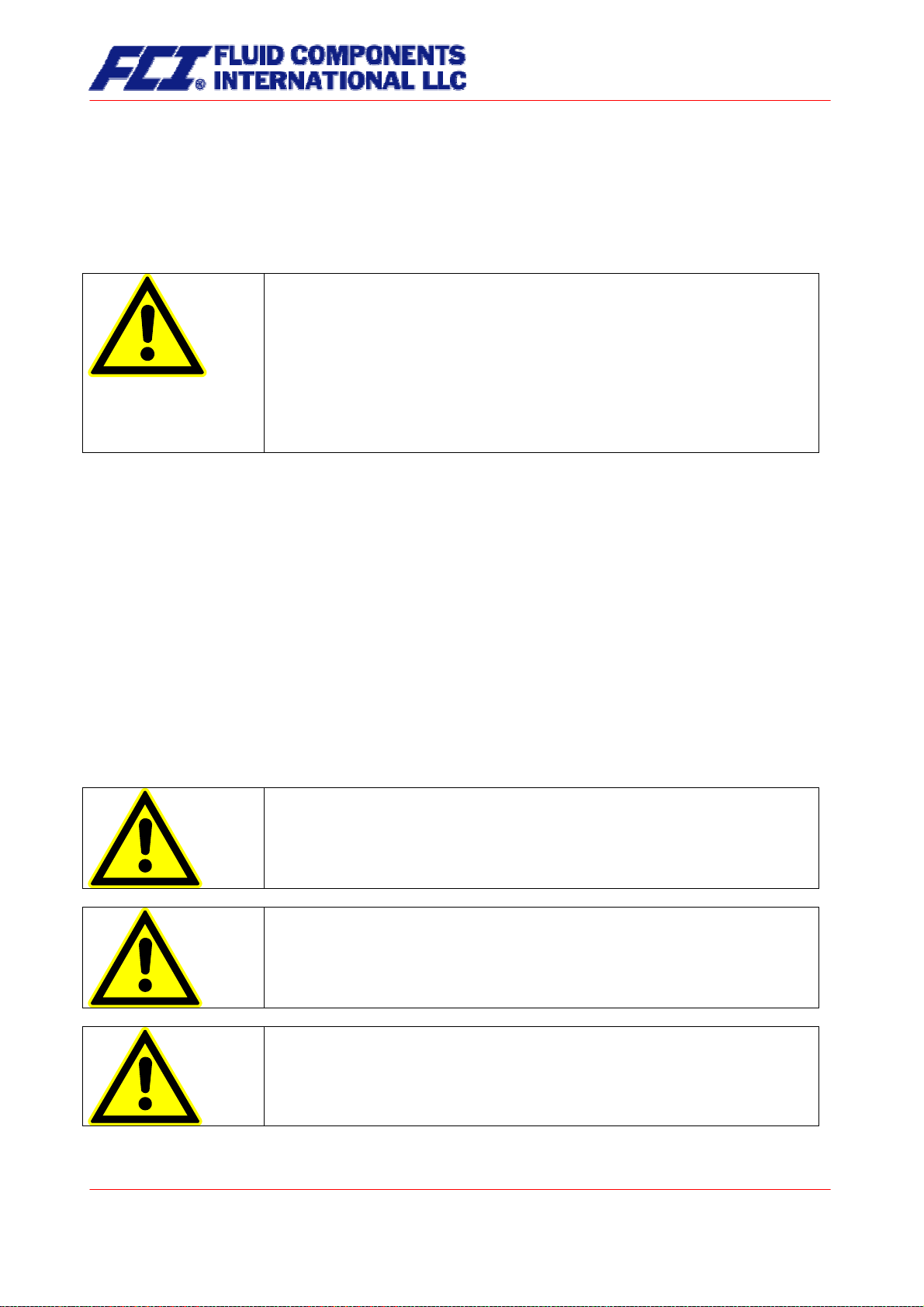
10. CT operating conditions
10.1 Installation conditions and cable glands
The integral mount version of the CT transmitter in the SG1 housing is to be installed in accordance with
Section 3.5.1 Installation on page 18. If the CT transmitter is installed separately, a vibration-free installation site must be ensured.
Warning:
Additional cable glands:
They are not contained in the scope of supply. The operator is responsible for
the fact that according to the enclosure and ignition enclosure certified cable
glands or screws are used. The kind of the thread is stamped on the rating
10.2 Environmental conditions
plate.
At the connection between sensor and transmitter a metalized cable gland
must be used for the screen.
(See 11.5.2.2 “Wiring diagram for the remote mount configuration of sensor
and CT” page 47)
10.2.1 Ambient temperature
− 20 °C to + 60 °C (-4 °F to 140 °F), below 0 °C (32 °F) the readability of the LC display will be limited.
10.2.2 Ambient temperature range
− 20 °C to + 60 °C (-4 °F to 140 °F)
10.2.3 Storage temperature
−25 °C to + 60 °C (-13 °F to 140 °F)
10.2.4 Ingress protection
Standard housing SG1, IP 68 (NEMA 6P)
Explosion-proof electronics housing
Terminal compartment: with terminals and “Increased safety” type of protection.
Warning:
Ingress protection IP 68 is only achieved if suitable and tightly screwed down
cable glands or conduit are used. If the cable glands are only tightened manually water may leak into the terminal compartment in the housing.
Danger:
Particular care must be taken if the window in the housing becomes fogged
over or discolored because moisture, water or product might seep through the
wire sheath into the terminal compartment in the housing.
Page 40 of 112
Warning
Electromagnetic compatibility is only achieved if the electronics housing is
closed. Leaving the enclosure open can lead to electromagnetic disturbances.
CMU & CT OPERATING MANUAL
Page 41

10.3 Process conditions
10.3.1 Fluid temperature
− 40 °C to + 260 °C (-40 °F to 500 °F)
The data sheet/rating plate of the connected transmitter must be observed.
10.3.2 Physical state
Liquid product (maximum density 2 kg/l (125lb/ft³))
Gaseous product (minimum density 0.002 kg/l in operating state)
10.3.3 Viscosity
0.3 to 50,000 mPas (0.3 to 50,000cP)
The data sheet of the connected transmitter must be observed.
10.3.4 Fluid temperature limit
260 °C (500 °F)
The data sheet of the connected transmitter must be observed.
10.3.5 Flow rate limit
See sensor data sheet in Section 3.4.2 CMU flow ranges on page 15.
10.3.6 Pressure loss
See sensor data sheet in Section 3.4.5 Pressure loss CMU on page 17.
CMU & CT OPERATING MANUAL
Part No 06EN003380 rev 1.6
Page 41 of 112
Page 42

11. Construction details
11.1 Type of construction/dimensions
Horizontal pipe mounting - SG1
1. Mount pipe to carrier.
2. Tighten U-bolt clamp around pipe.
3. Mount transmitter onto carrier.
Vertical pipe mounting - SG1
Separate mounting – SG1
Page 42 of 112
CMU & CT OPERATING MANUAL
Page 43
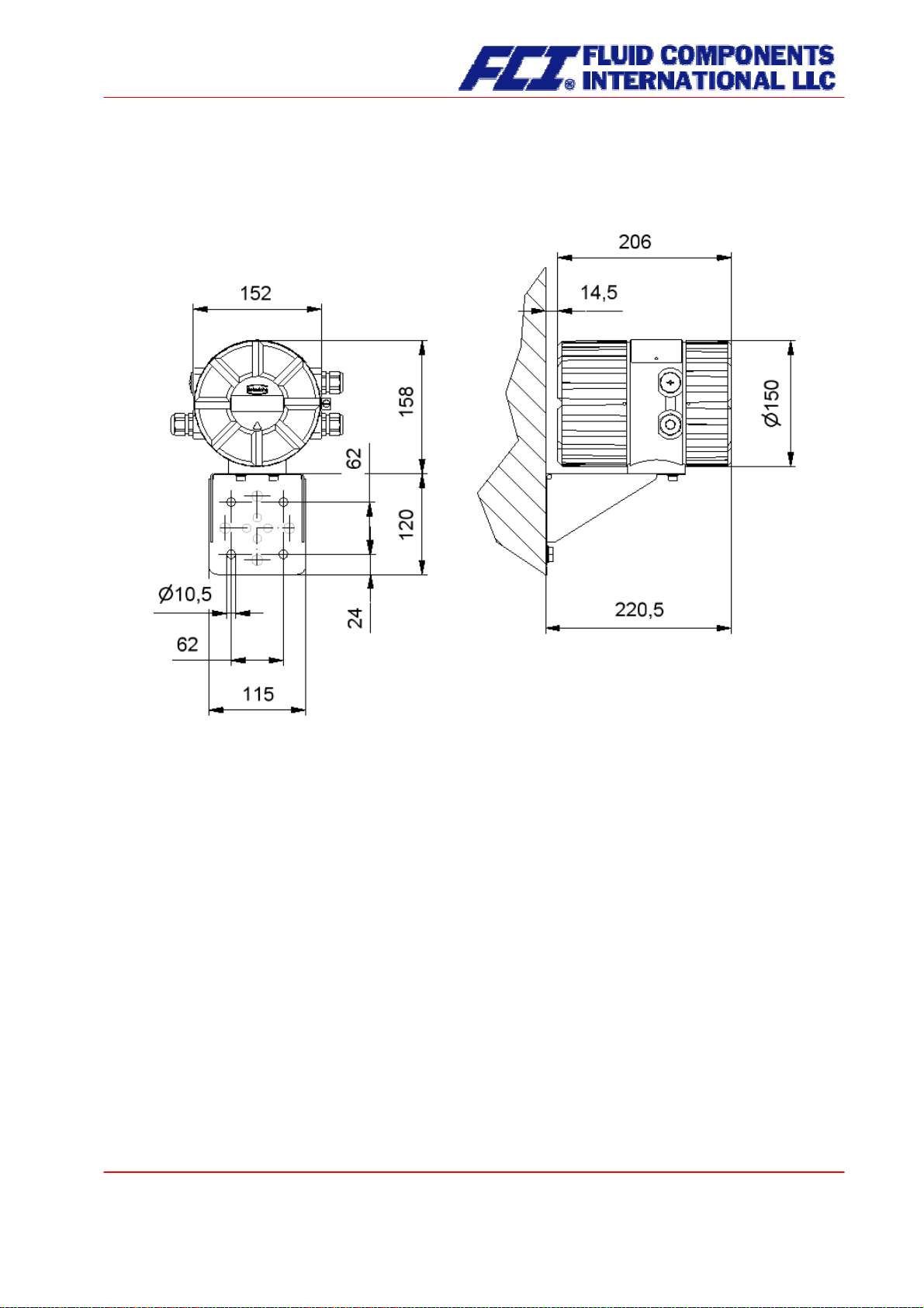
11.2 Weight
4.5 kg (10 lbs) (separate CT transmitter)
11.3 Material
Housing: GK Al Si 12 MG wa, passivated in chromic acid before being varnished
11.4 End connection
Direct (wireless) connection with the sensor or cable connection. For further details see Section 3.7
Connection to the transmitter on page 23, Section 11.5.2.1 Wiring diagram for the integral mount configuration of sensor and CT on page 46 and Section 11.5.2.2 Wiring diagram for the remote mount configuration of sensor and CT on page 47.
CMU & CT OPERATING MANUAL
Part No 06EN003380 rev 1.6
Page 43 of 112
Page 44

11.5 Electrical connection
Auxiliary power 90 V - 265 V AC 50/60 Hz
24 V AC + 20 %, − 20 % 50/60 Hz
19 V to 36 V DC
Power input 7.5 VA
Main fuse: 5x20 mm IEC 60127-2,V
Main voltage r. Current rated voltage breaking capacity
90V ... 265V AC 400mAT 250V AC 1500A / 250V AC
24V AV 800mAT 250V AC 1500A / 250V AC
11.5.1 CT connections
Lines
Designation Terminal designation Type of protection Standard
EEx ia EEx e (Not Ex)
Power supply
Sensor lines
SENSOR1 + 1 x x
SENSOR1 - 2 x x
SENSOR2 + 3 x x
SENSOR2 - 4 x x
TIk- 5 x x
Temperature sensor - 6 x x
Temperature sensor + 7 x x
TIk+ 8 x x
EXCITER1 9 x x
EXCITER2 10 x x
Shield Shield x x
19V ... 36V DC 800mAT 250V AC 1500A / 250V AC
L(+), N(-),PE x x
Page 44 of 112
CMU & CT OPERATING MANUAL
Page 45

Designation Terminal designation Type of protection Standard
EEx ia EEx e (Not Ex)
Signal outputs
with HART
®
11 and 12 x x Current 1, 0/4 to 20mA
41 and 42 x
13 and 14 x x Current 2, 0/4 to 20mA
43 and 44 x
16 and 17 x x Binary output 1
(passive pulse)
46 and 47 x
45 and 48 x Binary output 1
(active pulse)
15 and 18 x
19 and 20 x x Binary output 2
(status or second passive pulse output for
49 and 50 x
custody transfer opera-
tions)
33 and 34 x x Option
Binary output 3
(status output during
53 and 54 x
custody transfer opera-
tions)
Profibus PA option
Control unit BE
Alternatives for cur-
39 (A) and 40 (B) x
Shield, -, + x x
rent output 2
21 and 22 x x Binary input
51 and 52 x
Modbus/Profibus DP
with RS 485-IS
Profibus DP 37 (A) and 38 (B)
35 (A) and 36 (B)
(not currently available)
x x
x
(not currently available)
¾ Since the signal outputs cannot be activated simultaneously owing to the limited number of ter-
minals available, one of the aforementioned options must be selected.
(Profibus PA) are not outfitted with an analog or impulse output.
Field bus devices
¾ A maximum of 8 signal output terminals is available (in addition to the terminal for the control unit
and Profibus PA).
¾ “Increased safety” type of protection signal outputs are to be connected only to "Extra low volt-
age" degree of protection circuits with safe electrical isolation in accordance with DIN VDE 0100
part 410.
¾ Under no circumstances are “Increased safety” signal outputs to be combined with “In-
trinsic safety” signal outputs
.
¾ If interface output RS 485 (under development and not currently available), which is only avail-
able in an “Increased safety” model, is selected, all signal outputs must also have this type of protection.
¾ If “Control input” or “RS 485 interface” are selected, current output 2 is not supplied.
¾ If the sensor and transmitter are interconnected using a cable, the following cable is to be used:
SLI2Y (SP) CY 5 x 2 x 0.5 mm (for explosion-proof applications, grey for non-explosion
proof applications).
CMU & CT OPERATING MANUAL
Page 45 of 112
Part No 06EN003380 rev 1.6
Page 46

11.5.2 Wiring diagram
11.5.2.1 Wiring diagram for the integral mount configuration of sensor and CT
Supply and end connections
of the CT transmitter
Process outputs wiring
Standard EEx ia /
Not Ex Standard EEx e Custody transfer
17 + Binary output 1 47 + Binary output 1 17 + Binary output 1 17 + Binary output 1
(pulse/frequency) 46 - (pulse/frequency) 16 - (pulse/frequency) 16 - (pulse/frequency)
16 20 + Binary output 2 50 + Binary output 2 20 + Binary output 2 20 + Binary output 2
(status output) 49 - (pulse/frequency) 19 - (pulse/frequency) 19 - (pulse/frequency)
19 14 + Current output 2 44 + Current output 2 34 + Binary output 3 36 B RS485
(0/4-20 mA) 43 - (0/4-20 mA) 33 - (status output) 35 A (Modbus)
13 12 + Current output 1 42 + Current output 1 12 + Current output 1 12 + Current output 1
11 -
(0/4-20 mA HART®) 41 - (0/4-20 mA HART®) 11 - (0/4-20 mA HART®) 11 - (0/4-20 mA)
Note: RS 485 not currently available
Page 46 of 112
CMU & CT OPERATING MANUAL
Modbus (planned)
(RS485 - IS)
Page 47

11.5.2.2 Wiring diagram for the remote mount configuration of sensor and CT
Cable: Non-explosion proof applications SLI2Y(ST)CY 5 x 2 x 0.5 mm² grey (max. 300 m)
Explosion-proof applications SLI2Y(ST)CY 5 x 2 x 0.5 mm² blue (max. 300 m)
The outer shield is connected to the cable glands at both ends,
the inner shields are connected to each other and connected to the “Schirm / shield” terminal.
Schirm / shield
-
10
rosa / pink
-
9
grau / grey
-
8
schwarz / black
-
5
violett / violett
-
7
blau / blue
-
6
rot / red
-
4
gelb / yellow
-
3
grün / green
-
2
weiß / white
-
1
braun / brown
Schirm / shield
10
9
8
5
7
6
4
3
2
1
CMM, CMB, CMU with WAGO terminals
For terminal assignment, see Section 11.5.1 CT connections
-
rosa / pink
-
grau / grey
-
schwarz / black
-
violett / violett
-
blau / blue
-
rot / red
-
gelb / yellow
-
grün / green
-
weiß / white
-
braun / brown
Advices to cable glands: See also 10.1 “Installation conditions and cable glands” at page 40.
CMU & CT OPERATING MANUAL
Part No 06EN003380 rev 1.6
Page 47 of 112
Page 48
CMM, CMB, CMU with limit circuit and WAGO terminals
For the terminal assignment, see Section 11.5.1 CT connections
Cable glands: See also 10.1 “Installation conditions and cable glands” at page 40.
11.5.3 HART®
A number of options are available for HART® communication. However, for all these options loop resistance must be less than the maximum load specified in Section 8.3 Load (on page 39). The HART
®
inter-
face is connected via terminal 11 and 12 or 41 and 42 with a minimum load impedance of 250 ohms.
For information regarding operation of the transmitter using the HART
tion of the CT transmitter using the HART
®
hand-held terminal.”
®
hand-held terminal, see “Opera-
11.5.4 Communication via SensorPort
SensorPort is the configuration software that is used to operate HART® or Profibus PA compatible devices.
To connect a desktop or laptop computer to the CT, a HART
nication software such as SensorPort. The HART
®
interface, which has two connections, converts the
®
interface is required in addition to commu-
levels of the RS 232 interface into an FSK signal (frequency-shift keying). These connections consist of
9-pin sockets at the interface for the RS 232 connection, as well as a two-core cable with two mini terminals for current loop 1 in the transmitter.
The interface can be also installed in a separate control cabinet.
Page 48 of 112
CMU & CT OPERATING MANUAL
Page 49

12. Control unit BE2
12.1 Introduction
The CT transmitter can be operated using control unit BE2, a desktop or laptop computer in conjunction
with SensorPort software, or via HART
In the following, transmitter operation and parameterization using control unit BE2 (normally integrated
into the terminal compartment) are described. The control unit can also be connected to the transmitter
using an intrinsically safe cable that is up to 200 m in length. This allows a point-of-use display to be installed in a control room so that readings, counter status and settings can be accessed ergonomically.
®
Communicator.
12.2 Display
Control unit BE2 in the CT has an integrated alphanumeric display with two 16-character lines (format 16
x 60 mm). Measurement data and settings can be read directly from this display.
The LCD display is designed be operated at temperatures ranging from − 20 °C to + 60 °C (-4° F to
140 °F) without incurring any damage. However, at freezing or near-freezing temperatures, the display
becomes slow and readability of the measured values is reduced. At temperatures below − 10 C° (14 °F),
only static values (parameter settings) can be displayed. At temperatures exceeding 60 C° (140 °F), contrast decreases substantially on the LCD and the liquid crystals can dry out.
CMU & CT OPERATING MANUAL
Part No 06EN003380 rev 1.6
Page 49 of 112
Page 50

12.3 Operating modes
The CT can be operated in the following modes:
1. Display mode: In display mode, measured values can be displayed in various
combinations and CT settings can also be displayed. Parameter
settings cannot be changed in this mode. Display mode is the
standard (default) operating mode when the device is switched on.
2. Programming mode: In programming mode, CT parameters can be redefined. After
entering the correct password, changes that are permissible for the
customer (customer password) or all functions (service password
for technicians) can be realized.
12.4 Operation
12.4.1 Operator interface
Functional classes
headings beneath which displays and
parameters are shown in logical
groups.
Beneath this is the
lists all measured value displays or
the headings for their underlying parameters (
parameter level).
All functional classes are interlinked
horizontally, while all subpoints that
are assigned to a functional class are
displayed beneath the relevant class.
are displayed as
menu level, which
Functional class
Func tional clas s
Function with
Function with
numerical Input
numerical Input
Display
Display
Legend
Headline
Main menu
Numerical Input
153.40
Menu level subpoint
Functionial class
Functionial class
Parameter level
Function
Function
value selec ted from
value selected from
list
list
Selection
[no]
___________
no
yes
Page 50 of 112
CMU & CT OPERATING MANUAL
Page 51

12.4.2 The keys and their functions
There are six keys to change the settings.
Important note
Do not press these keys with sharp or sharp-edged objects such as pencils or
screwdrivers.
Cursor keys: Using the cursor keys, the operator can change numerical values, give YES/NO answers
Esc key:
ENTER key: Pressing
and select parameters. Each key is assigned a symbol in the following table:
Descriptor Symbol
Cursor key, arrow to the right
Cursor key, arrow to the left
Cursor key, arrow to the top
Cursor key, arrow to the bottom
The “Esc” key allows you to cancel the current action. Pressing Esc moves you to
the next higher level where the operator can repeat the action.
you directly to the MEASURED VALUES functional class.
↵ (ENTER key) moves you from the menu level to the parameter level. You
confirm all entries with the
↵ key.
4
3
5
6
Pressing Esc twice moves
CMU & CT OPERATING MANUAL
Part No 06EN003380 rev 1.6
Page 51 of 112
Page 52

12.4.3 Functional classes, functions and parameters
Functional classes are written in all upper case letters (headings). The functions beneath each functional
class are written in upper and lower case.
The various functional classes and functions are describes in Section 13 “CT transmitter functions” starting on page 54.
The lower lines contains the following elements:
- Informational texts
- YES/NO answers
- Alternative values
- Numerical values (with dimensions, if applicable)
- Error messages
If the user attempts to modify values for any of these parameters without entering the required password,
the message “Access denied” will be displayed (see also 12.3 Operating modes on page 50 and 12.4.3.3
Pas on page 53).
12.4.3.1 Selection window/make a selection
In the selection window, the first line of the LCD always contains the heading, while the second line displays the current setting. This setting is shown in square brackets if the system is in Programming mode.
Function name
[Selection]
In Programming mode (see 12.3 Operating modes on page 50), i.e. after a password has been entered
(see 12.4.3.3 Passwords on page 53), the operator can navigate to the desired setting by using the
or the
6key and the operator can then confirm your selection by pressing ↵ (ENTER key). To retain the
5key
current setting, press Esc.
Page 52 of 112
CMU & CT OPERATING MANUAL
Page 53

12.4.3.2 Input window/modify a value
In the input window, the first line of the LCD always shows the heading, while the second line
shows the current setting.
Example:
Function name
-4,567 Unit
These modifications can only be made in Programming mode (refer to 12.3 Operating modes on page
50), which means that a correct password (see 12.4.3.3 Passwords on page 53) must be entered. To
move the cursor from one decimal place to the next, use the
decimal place just under the cursor by “1,” use the
change the minus and plus sign, place the cursor in front of the first digit. To confirm and apply the
change, press
12.4.3.3 Passwords
Programming mode is password protected. The customer password allows all changes to be made that
are permissible for customers. This password can be changed when the device is first put into operation.
Such changes should be kept in a safe place.
The CT customer password in the device when delivered is
The service password allows for modification of all CT functions. This password is not given to customers.
For further information on customer passwords, see Section 13.2 PASSWORD functional class on page
60.
↵ . To retain the current value, press Esc.
5key, and use 6key to lower the number by 1. To
3or4keys. To increase the value of the
0002.
CMU & CT OPERATING MANUAL
Part No 06EN003380 rev 1.6
Page 53 of 112
Page 54

13. CT transmitter functions
The software functions of the CT transmitter are divided into functional classes, are arrayed in a circle
and can be navigated by using the
3or4cursor keys. To go back to your starting point (the MEASURED
VALUES functional class) press Esc.
Function Overview
(Main Menue)
MEASURED
MEASURED
VALUES
SENSOR
SETTINGS
TRANSMITTER
TRANSMITTER
SETTINGS
SETTINGS
UMC3
UMC3
SENSOR
SETTINGS
VALUES
PASSWORD
PASSWORD
COUNTER
COUNTER
SELF-TEST
SELF-TEST
SIMULATION
SIMULATION
CURRENT
CURRENT
OUTPUT
OUTPUT
STATUS
STATUS
PULSE OUTPUT
PULSE OUTPUT
DENSITY
TEMPERATURE
TEMPERATURE
DENSITY
MEASUREMENT
MEASUREMENT
PROCESSING
PROCESSING
FLOW
FLOW
In the following, all software functions that can be accessed using the customer password are described.
Functions that are only accessible to the vendor (service functions) are not described in the present
document.
Page 54 of 112
CMU & CT OPERATING MANUAL
Page 55
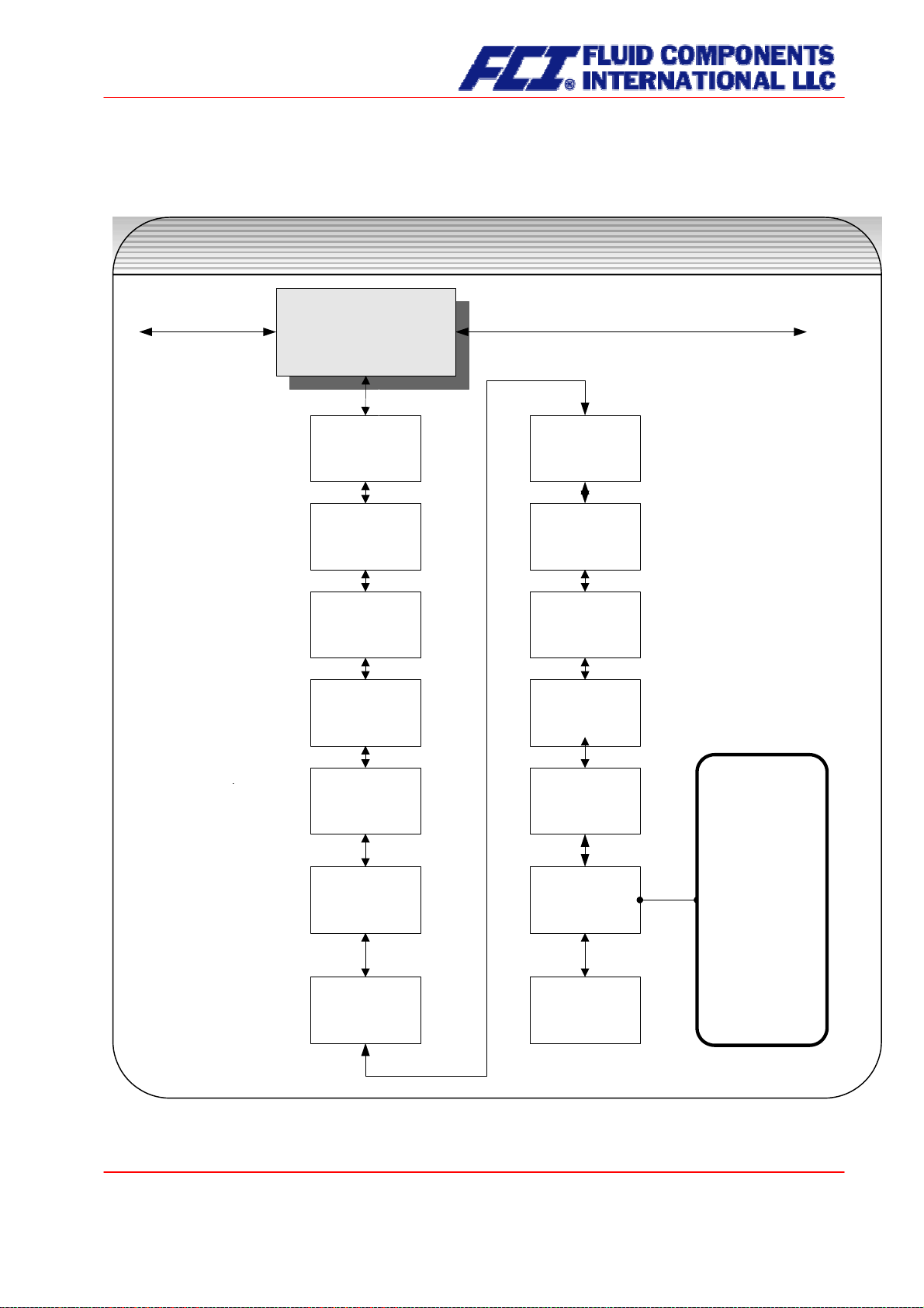
13.1 MEASURED VALUES functional class
The MEASURED VALUES functional class contains all functions for displaying the measured values.
MEASURED VALUES
functional class
MEASURED VALUES
MEASURED VALUES
Mass flow
Mass flow
(QM)
(QM)
Volume flow
Volume flow
(QV)
(QV)
Counter forward
Counter forward
(F)
(F)
Counter reverse
Counter reverse
(R)
(R)
Density
Density
Temperature
Temperature
Elapsed time
Elapsed time
d h min
d h min
Mass flow
Mass flow
Counter (F)
Counter (F)
Mass flow
Mass flow
Density
Density
Mass flow
Mass flow
Temperature
Temperature
QV
QV
Counter (F)
Counter (F)
QV
QV
Density
Density
Display mode
Display mode
start -up
start -up
Raw values
Raw values
Display mode
[QM]
_______________
QM
QV
Counter F
Counter R
Density
Temperature
QM + Counter F
QM + Density
QM + temperature
QV + Counter F
QV + Density
Raw values
CMU & CT OPERATING MANUAL
Page 55 of 112
Part No 06EN003380 rev 1.6
Page 56

13.1.1 Mass flow
After selecting the Mass flow function, the following will be displayed:
Mass flow
XXX.X kg/h
The LCD shows the current mass flow. The operator can define the display unit in the FLOW functional
class using the
Mass flow QM unit function.
13.1.2 Volume flow
After selecting the
Volume flow function, the following will be displayed:
Volume flow
XXX.X m³/h
Volume flow can only be displayed if density measurement has been calibrated and activated. Otherwise,
an error message is displayed. The operator can define the display unit in the FLOW functional class
using the
Volume flow QV unit function.
13.1.3 Counter forward
After selecting the
Counter forward function, the current reading of the forward flow counter will be dis-
played.
Counter forward
XXXXXXXX.XX kg
The operator can define the display unit in the COUNTERS functional class using the
function.
13.1.4 Counter reverse
After selecting the
Counter reverse function, the current reading of the reverse flow counter will be dis-
played.
Counter reverse
XXXXXXXX.XX kg
The operator can define the display unit in the COUNTERS functional class using the
function.
Unit of counters
Unit of counters
Page 56 of 112
CMU & CT OPERATING MANUAL
Page 57

13.1.5 Density
Depending on the settings in the DENSITY functional class, the process or reference density will be displayed. Density can only be displayed if the sensor is suitable for density measurement and has been
calibrated accordingly.
Density
XXX.X g/l
The operator can define the display unit in the DENSITY functional class using the
Density unit function.
13.1.6 Temperature
After selecting the
Temperature function, the following will be displayed:
Temperature
XXX.XX °C
The LCD shows the current temperature of the measured fluid in degrees Celsius, Fahrenheit or Kelvin.
13.1.7 Elapsed time
The LCD shows the operating time that has elapsed in d(ays), h(ours) and min(utes) since the system
was initialized and commissioned by the vendor:
Elapsed time
256 d 18 h 06 min
13.1.8 Mass flow + Counter forward
After selecting the
Mass flow + Counter forward function, the current mass flow will be displayed in the
first line of the LCD:
XXX.X kg/h
XXXXXXXX.XX kg
The second line shows the value of the counter forward. The operator can define the display unit in the
FLOW functional class using the
function in the COUNTERS functional class.
ers
Mass flow QM unit function and the counter unit using the Unit of count-
CMU & CT OPERATING MANUAL
Part No 06EN003380 rev 1.6
Page 57 of 112
Page 58

13.1.9 Mass flow + Density
After selecting the
The first line of the LCD shows the current mass flow and the second the density of the measured fluid.
You define the display unit in the FLOW functional class using the
density unit using the
13.1.10 Mass flow + Temperature
After selecting the
Mass flow + Density function, the following will be displayed:
XXX.X kg/h
XXX.X g/cm³
Density unit function in the DENSITY functional class.
Mass flow + Temperature function, the following will be displayed:
XXX.X kg/h
Mass flow QM unit function and the
XXX °C
The first line of the LCD shows the current mass flow and the second line the temperature of the
measured fluid. You define the display unit in the FLOW functional class using the Mass flow
QM unit function.
13.1.11 Volume flow + Counter forward
After selecting the
first line of the LCD:
The second line shows the value of the counter forward. The operator can define the display unit in the
FLOW functional class using the
counters
After selecting the
The first line of the LCD shows the current volume flow and the second line the density of the measured
fluid. The operator can define the display unit in the FLOW functional class using the
unit
function.
function in the COUNTERS functional class.
13.1.12 Volume flow + Density
function and the unit for density measurement in the DENSITY functional class using the Density unit
Volume flow + Counter forward function, the current mass flow will be displayed in the
XXX.X m³/h
XXXXXXXX.XX m³
Volume flow QV unit function and the counter unit using the Unit of
Volume flow + Density function, the following will be displayed:
XXX.X m³/h
XXX.X g/cm³
Volume flow QM
Page 58 of 112
CMU & CT OPERATING MANUAL
Page 59

13.1.13 Display mode during startup
By choosing the
Display mode during startup function the operator can define the default display. After
the operator switched the device on and did not touch any keys for a longer period of time, the defined
default display will be shown:
Display mode
[QM]
According to the description in Section 12.4.3.1 Selection window/make a selection, one of the following
default displays can be selected.
¾ QM (Mass flow)
¾ QV (Volume flow)
¾ Counter f(orward)
¾ Counter r(everse)
¾ Density
¾ Temperature
¾ QM + Counter f
¾ QM + Density
¾ QM + Temperature
¾ QV + Counter f
¾ QV + Density
¾ and Raw values
13.1.14 Raw values
The “Raw values display” supports fault diagnosis and trouble shooting. Please inform our service department about the clear text error messages and the contents of this “Raw values display.”
xxx.xxx ttt.tttt
fff.ffff eee.aaa
The displayed values have the following meaning:
xxx.xxx: Measure for the phase displacement between the sensor signals.
ttt.ttt: Indicates the measured sensor temperature.
fff.ffff: Indicates the current oscillation frequency of the system.
eee.aaa: Indicates the value of the excitation current (eee) and the sensor voltage (aaa).
CMU & CT OPERATING MANUAL
Part No 06EN003380 rev 1.6
Page 59 of 112
Page 60

13.2 PASSWORD functional class
The PASSWORD functional class is comprised of the functions for entering and changing the customer
password and entering the service password. To cancel the current action, press Esc.
PASSWORD
functional class
PASSWORD
PASSWORD
Customer
Customer
password
password
Change customer
Change customer
password
password
Service
Service
password
password
Password ?
0000
Enter New password
0000
Password ?
0000
13.2.1 Customer password
After selecting the
Customer password function and pressing ↵, the following will be displayed:
Password?
0000
According to the description in Section 12.4.3.2 Input window/modify a value, the password can be
changed.
If the entered password is correct, the following message will be displayed:
Password
valid
If the entered password is not correct, the following message will be displayed:
Password
invalid
The customer password in the device when delivered is
0002.
Page 60 of 112
CMU & CT OPERATING MANUAL
Page 61

A valid customer password allows all software parameter changes to be made that are permissible for
customers. After the operator switched the device off or did not touch any keys for about 15 minutes, the
authorization to change settings related to password entry will automatically be canceled. If the operator
does not enter a valid password, all settings can be displayed but not changed. Parameter changes via
HART or Profibus PA may be carried out any time without entering password.
13.2.2 Change customer password
After entering a valid customer password, you may change the existing password and enter a new one.
After selecting the
Change customer password function and pressing ↵, the following will be displayed.
Enter New password
0000
According to the description in Section 12.4.3.2 Input window/modify a value the current value can be
changed.
Press ↵ to confirm and save the new password. Make sure that you entered the desired pass-
word.
A copy of the password should be kept in a safe place. Reactivation of a transmitter at the ven-
dor’s site due to a lost password is not part of our warranty.
13.2.3 Service password
You do not need the service password for setting the functions necessary for operation.
The service password is reserved for service technicians and not provided to customers. Correct settings
are essential for proper operation of the device (e.g. parameterization and calibration values).
CMU & CT OPERATING MANUAL
Part No 06EN003380 rev 1.6
Page 61 of 112
Page 62
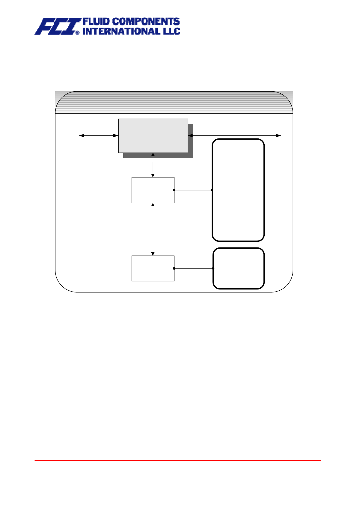
13.3 COUNTER functional class
The COUNTERS functional class is comprised of the following functions:
COUNTERS
functional class
COUNTERS
COUNTERS
Accumulation of:
_________________
Unit of
Unit of
counters
counters
[kg]
g
kg
t
m³
l
USG
UKG
USB
lbs
shton
lton
ft³
acft
Reset counters ?
Reset
Reset
counters
counters
[no]
________________
no
yes
To change the current settings, enter the customer password. Otherwise, the settings can only be displayed but not changed. To cancel the current action, press Esc.
Page 62 of 112
CMU & CT OPERATING MANUAL
Page 63

13.3.1 Unit of counters
After choosing the
Unit of counters function and pressing ↵, the current forward and reverse counter unit
will be displayed:
Accumulation of:
[kg]
According to the description in Section 12.4.3.1 Selection window/make a selection, one of the following
units can be selected.
¾ Mass units: g, kg, and t as well as lbs, shton and lton
¾ Volume units: m³, and l as well as USG, UKG, USB, ft³ and acf
When the unit is changed, the counters will be reset to 0.00 automatically.
The volume unit only makes sense if the sensor has been calibrated for density measurement. Press ↵
to confirm and save the selection. Forward and reverse counters will now show the selected unit.
13.3.2 Reset counters
To reset the totalizing counters, you definitely need to toggle to [yes]. Forward and reverse counters will
be reset at the same time (0.00).
Reset counters
[no]
According to the description in Section 12.4.3.1 Selection window/make a selection, one of the indicated
units can be selected. By pressing Esc or toggling to [no] the operator can cancel the current action without changing the counter readings.
CMU & CT OPERATING MANUAL
Part No 06EN003380 rev 1.6
Page 63 of 112
Page 64
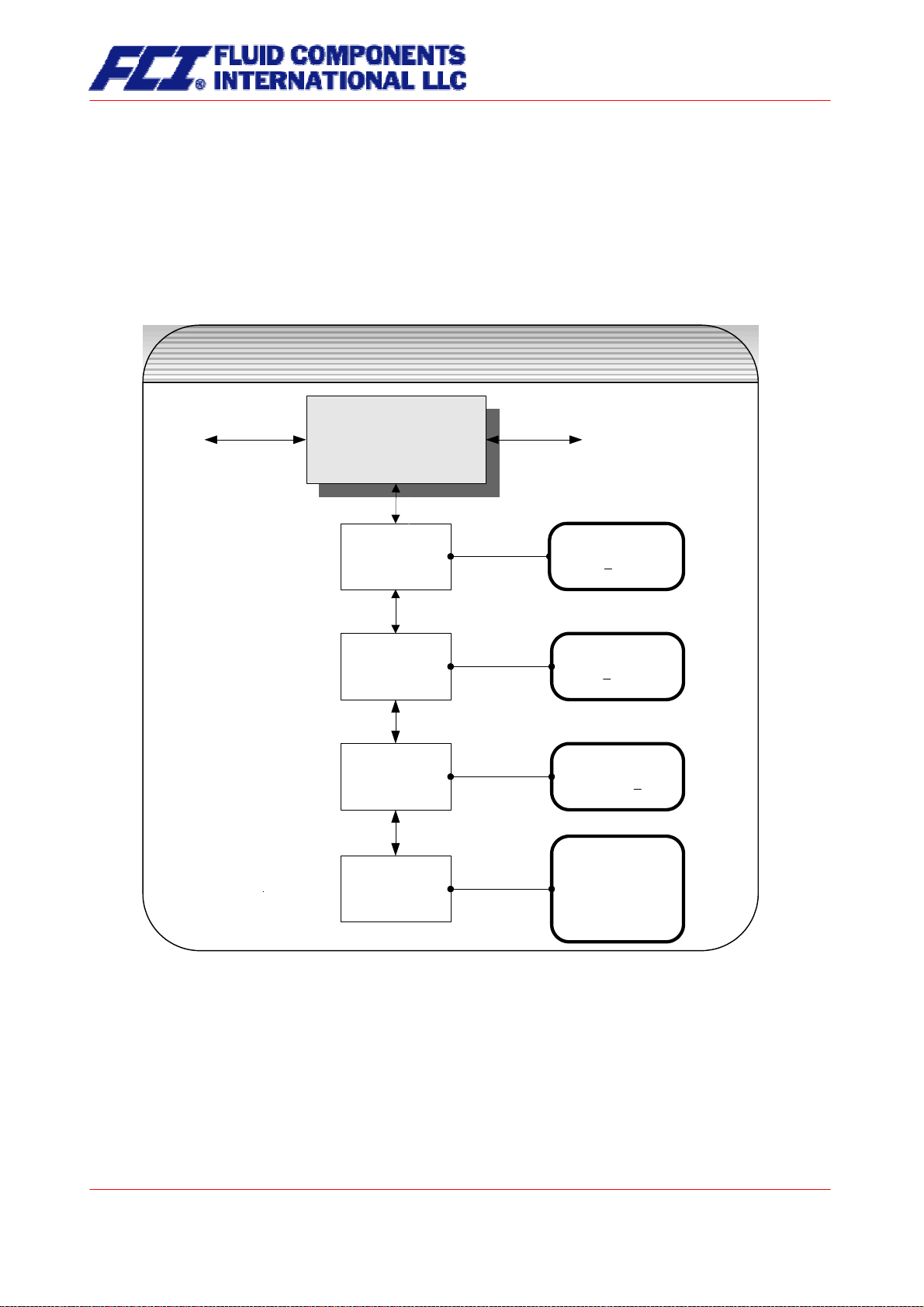
13.4 MEASUREMENT PROCESSING functional class
The MEASUREMENT PROCESSING functional class is comprised of all functions that affect the processing of the measured values.
To change the current settings, enter the customer password. Otherwise, the settings can only be displayed but not changed. To cancel the current action, press Esc.
MEASUREMENT PROCESSING
functional class
MEASUREMENT
MEASUREMENT
PROCESSING
PROCESSING
Damping
Damping
Low flow cut-off
Low flow cut-off
Low flow cut -off
Low flow cut -off
hysteresis
hysteresis
Zeropoint
Zeropoint
calibration
calibration
Damping
03 s
Low flow cut-off
01 %
Low flow cut -off
Hysteresis 01 %
x.xxx kg/h
cal. ? [no]
_________________
no
yes
Page 64 of 112
CMU & CT OPERATING MANUAL
Page 65

13.4.1 Damping
The damping value is intended to dampen abrupt flow rate changes or disturbances. It affects the measured value display and the current and pulse outputs. It can be set in intervals of 1 second from 1 to 60
seconds. After choosing the
Damping value function and pressing ↵, the following selection field will be
displayed:
Damping
03 s
The current damping value will be displayed. According to the description in Section 12.4.3.2 Input window/modify a value, the current value can be changed. After setting the new damping value, press
↵ to
confirm your entry.
13.4.2 Low flow cut-off
The value for low flow cut-off (low flow volume) is a limiting value stated as a percentage that relates to
the upper-range value of the flow rate. If the volume drops below this value (e.g. leakage), the displayed
value and the current outputs will be set to “ZERO.” The value for low flow cut-off can be set from 0 to
20 % in 1-percent increments. After choosing the
Low flow cut-off function and pressing ↵, the following
selection field will be displayed:
Low flow cut-off
00 %
The low flow volume will be displayed. According to the description in Section 12.4.3.2 Input window/modify a value, the current value can be changed. After setting the new low flow volume, you confirm
your entry with
↵.
For devices used in custody transfer operations, you need to deactivate the low flow cut-off function, i.e.
to set this value to 0 %.
13.4.3 Low flow cut-off hysteresis
The hysteresis of the low flow volume is the flow rate expressed as a percentage of the upper range
value by which the volume must fall below or surpass the set low flow volume in order to activate or deactivate the function. The hysteresis of the low flow volume can be set in 1-percent increments from 0 to
10 %. After selecting the
Low flow cut-off hysteresis function and pressing ↵, the following selection field
will be displayed:
Low flow cut-off
Hysteresis 00 %
The current hysteresis will be displayed. According to the description in Section 12.4.3.2 Input window/modify a value, the current value can be changed. After setting the new hysteresis value, you confirm your entry with
↵.
CMU & CT OPERATING MANUAL
Part No 06EN003380 rev 1.6
Page 65 of 112
Page 66

13.4.4 Zero point calibration
Using the
Zero point calibration function the operator can recalibrate the zero point of your meter in the
measuring system. Zero point calibration is to be realized after any installation procedure or after any
type of work has been performed on in the pipes near the sensor.
CAUTION:
This function may only be carried out if it is certain that the fluid in the sensor is not flowing. Otherwise, the flow rates measured subsequently will be incorrect. The sensor may
be completely empty or filled with fluid. A partially filled sensor or air bubbles will lead to
an incorrect zero point calibration.
Calibrating a sensor filled with a fluid is better than calibrating an empty one.
After choosing the
Zero point calibration function and pressing ↵, the current remaining flow will be dis-
played:
QM = 0.00 kg/h
cal. ? [no]
According to the description in Section12.4.3.1 Selection window/make a selection, the operator can toggle between [yes] and [no]. After setting the new value, press
↵ to confirm your entry. Enter [yes] to have
the zero point recalibrated.
Page 66 of 112
CMU & CT OPERATING MANUAL
Page 67
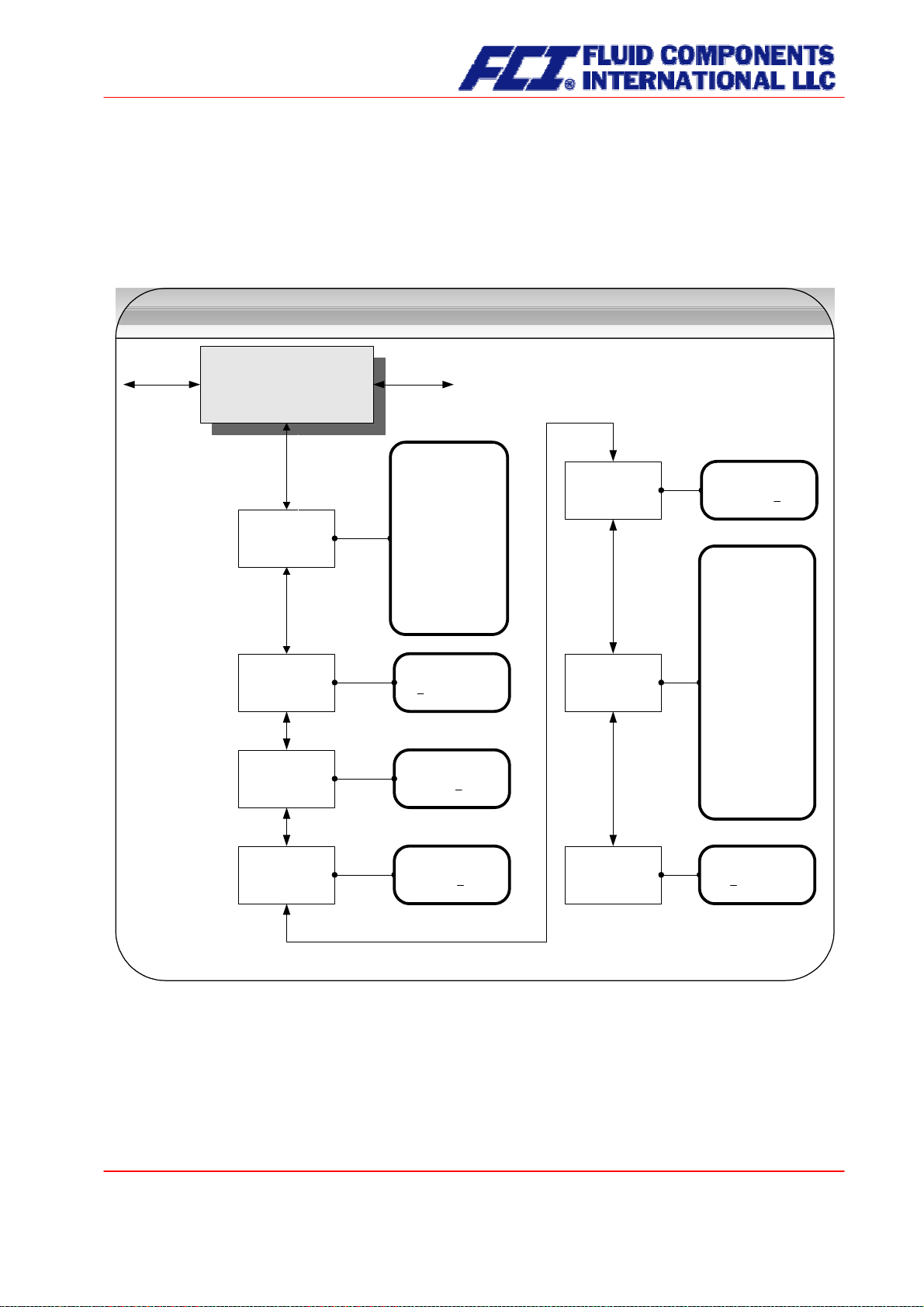
13.5 FLOW functional class
The FLOW functional class is comprised of functions that affect lower- and upper-range values and the
processing of the measured flow rates. In Programming mode (see 12.3 Operating modes), i.e. after a
password has been entered (see 12.4.3.3 Passwords, 13.2 PASSWORD functional class), the operator
can change the settings regarding flow.
FLOW
functional class
FLOW
FLOW
Mass flow in
Mass flow QM unit
Mass flow QM unit
mass flow
mass flow
QM range
QM range
Mass flow
Mass flow
QM limit MIN
QM limit MIN
[kg/h]
_________________
kg / s
kg / min
kg / h
t / h
g / min
lbs / s
lbs /min
lbs / h
shton / h
lton / h
QM Range = 100%
00120.00 kg/h
Mass flow limit
MIN = 10 %
Mass flow limit
Mass flow limit
hysteresis
hysteresis
Volume flow unit
Volume flow unit
QV
QV
Mass flow limit
hysteresis 01 %
Volume flow in
[l / h]
________________
m³ / h
l / h
l / min
l / s
USG / h
USG / min
USG / s
UKG / h
UKG / min
UKG / s
USB / d
MG / d
m³ / s
ft³ / min
acft / s
Mass flow
Mass flow
QM limit MAX
QM limit MAX
Mass flow limit
MAX = 90 %
Volume flow
Volume flow
QV range
QV range
QV Range = 100 %
0120.00 l/h
To change the current settings, enter the customer password. Otherwise, the settings can only be displayed but not changed. To cancel the current action, press Esc.
CMU & CT OPERATING MANUAL
Page 67 of 112
Part No 06EN003380 rev 1.6
Page 68

13.5.1 Mass flow QM unit
Using this function, the operator can define the physical unit for all display functions, limit values and the
upper-range value of mass flow. After choosing the
Mass flow QM unit function and pressing ↵, the fol-
lowing selection field will be displayed:
Mass flow QM unit
[kg/h]
According to the description in Section 12.4.3.1 Selection window/make a selection, one of the following
units can be selected:
¾ kg/s, kg/min, kg/h
¾ t/h
¾ g/min
¾ lbs/s, lbs/min, lbs/h
¾ shton/h
¾ lton/h
↵ to confirm and save the selection.
Press
13.5.2 Mass flow QM range
This function allows the operator to set the upper-range value for mass flow. The upper-range value
takes on the unit defined using the
and frequency outputs assigned to mass flow. After choosing the
pressing
↵, the following selection field will be displayed:
Mass flow unit function. The upper-range value will scale the current
Mass flow QM range function and
QM range=100%
XXXXX.XX kg/h
The current upper-range value for mass flow will be displayed. According to the description in Section
12.4.3.2 Input window/modify a value, the current value can be changed.
Page 68 of 112
CMU & CT OPERATING MANUAL
Page 69

13.5.3 Mass flow QM limit MIN
The MIN limiting value for mass flow can be evaluated via the status output. You enter the value as a
percentage of the set upper-range value. If the mass flow is lower than that limit value, the status output
will be set in case the corresponding assignment has been made. If the alarm function has also been
activated for the assigned current output, the applied current will change to < 3.2 mA or > 20.5 mA /
22 mA. After choosing the
Mass flow QM limit MIN function and pressing ↵, the following selection field
will be displayed:
Mass flow limit
MIN = 10 %
The current MIN upper-range value for mass flow will be displayed. According to the description in Section 12.4.3.2 Input window/modify a value, the current value can be changed.
13.5.4 Mass flow QM limit MAX
The MAX limiting value for mass flow can be evaluated via the status output. You enter the value as a
percentage of the set upper-range value. If the mass flow surpasses this limit value, the status output will
be set in case the corresponding assignment has been made. If the alarm function has also been activated for the assigned current output, the applied current will change to < 3.2 mA or > 20.5 mA / 22 mA.
After choosing the
Mass flow QM limit MAX function and pressing ↵, the following selection field will be
displayed:
Mass flow limit
MAX = 90 %
The current MAX upper-range value for mass flow will be displayed. According to the description in Section 12.4.3.2 Input window/modify a value, the current value can be changed.
13.5.5 Mass flow QM limit hysteresis
The hysteresis of the QM limiting values is the flow rate in percent based on the upper-range value and
indicates the value which must fall below or surpass the set limiting values in order to activate or deactivate the function. The hysteresis of the QM limiting values can be set in 1-percent increments from 0 to
10 %. After choosing the
Mass flow QM limit hysteresis function and pressing ↵, the following selection
field will be displayed:
Mass flow limit
Hysteresis 00 %
The current hysteresis value will be displayed. According to the description in Section 12.4.3.2 Input window/modify a value, the current value can be changed.
CMU & CT OPERATING MANUAL
Part No 06EN003380 rev 1.6
Page 69 of 112
Page 70

13.5.6 Volume flow QV unit
This function allows the operator to define the physical unit for all display functions and the upper-range
value for volume flow. After choosing the “Volume flow QV unit” function and pressing
↵, the following
selection field will be displayed:
Volume flow QV unit
in [m³/h]
According to the description in Section 12.4.3.1 Selection window/make a selection, one of the following
units can be selected:
¾ m³/h, m³/s
¾ l/h, l/min, l/s
¾ USG/h, USG/min, USG/s
¾ UKG/h, UKG/min, UKG/s
¾ USB/d
¾ MG/d
¾ ft³/min
¾ acft/s
↵ to confirm and save the selection.
Press
13.5.7 Volume flow QV range
This function allows the operator to set the upper-range value for volume flow. The upper-range value
takes on the unit defined using the
range
function and pressing ↵, the following selection field will be displayed:
Volume flow QV unit function. After choosing the Volume flow QV
QV range=100 %
XXXXX.XX m³/h
The current upper-range value for volume flow will be displayed. According to the description in Section
12.4.3.2 Input window/modify a value, the current value can be changed. Output and display of the measured value will only be realized for mass flowmeters for which a density calibration has been carried out.
Page 70 of 112
CMU & CT OPERATING MANUAL
Page 71

13.6 DENSITY functional class
The functional class DENSITY is comprised of the functions that affect the lower- and the upper-range
value and the processing of the measured density values. The additional service functions regarding
density calibration will not be described in these instructions.
CMU & CT OPERATING MANUAL
Part No 06EN003380 rev 1.6
Page 71 of 112
Page 72
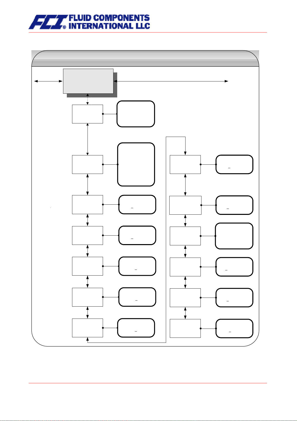
DENSITY
functional class
DENSITY
DENSITY
Measurement
Density
Density
measurement
measurement
on/off
on/off
Density unit
Density unit
[on]
________________
on
off
fixed
Density in
[g / l]
_______________
kg / l
g / l
g / cm³
lbs / ft³
lbs / USG
Density limit
Density limit
for empty pipe
for empty pipe
Pipe emty below
0500 g/l
Density
Density
lower range val
lower range val
Density
Density
upper range val
upper range val
Density
Density
limit MIN
limit MIN
Density
Density
limit MAX
limit MAX
Density limit
Density limit
hysteresis
hysteresis
Density 0 % =
0600 g/l
Density 100 % =
1100 g/l
Density
MIN = 0979.0 g/l
Density
MAX = 1200.0 g/l
Density limit
Hyst.= 000.5 g/l
Fixed density
Fixed density
setting
setting
Display ref./
Display ref./
Process dens.
Process dens.
Ref.-density
Ref.-density
Temp. coeff.
Temp. coeff.
Ref.-density
Ref.-density
Ref. temperature
Ref. temperature
Ref.-density
Ref.-density
Ref. pressure
Ref. pressure
Fixed density
0998.1 g/l
Display of
[Process density]
________________
Reference density
Process density
Temp.coeff.
+00.000 E-5/K
Ref. temperature
015.00 °C
Ref.pressure
001.000 bar
13.6.1 Density measurement on/off
This function allows the operator to activate density measurement. After selecting the
ment on/off
function, press ↵ to display the following selection field:
Density measure-
Page 72 of 112
CMU & CT OPERATING MANUAL
Page 73

Measurement
[on]
As mentioned in Section 12.4.3.1 Selection window/make a selection, the operator can choose between
the following settings:
• on density measurement is switched on
• off density measurement is switched off
• fixed density measurement is switched off; a fixed replacement value will be displayed
and used for volume flow measurement
•
To confirm and apply the selection, press
↵. If density measurement was switched on and the message
“Density not calibrated” is displayed, no density calibration was carried out by the vendor.
Density measurement can only be activated if density calibration has been carried out properly.
Density calibration is realized at the factory using the service password.
If no density calibration has been carried out, the density and volume flow values will be set to
“0.0” in the MEASURED VALUES functional class and the message “Density unknown” will be displayed.
13.6.2 Density unit
This function allows the operator to define the physical unit for all display functions and the density lowerand upper-range value. After selecting the
Density unit function, press ↵ to display the following selection
field:
Density unit
[g/l]
As mentioned in Section 12.4.3.1 Selection window/make a selection, the operator can choose between
the following units:
¾ g/l
¾ kg/l
¾ g/cm³
¾ lbs/ft³
¾ lbs/USG
Press
↵ to confirm and apply the selection.
CMU & CT OPERATING MANUAL
Part No 06EN003380 rev 1.6
Page 73 of 112
Page 74

13.6.3 Density lower-range value
This function allows the operator to define the lower-range value for density measurement in the selected
unit. If density is equal or below this value, the assigned current output will be set to its initial value of
0/4 mA.
After selecting the
Density lower-range value function, press ↵ to display the following selection field:
Density 0 % =
XXXXX g/l
The current lower-range value will be displayed. As mentioned in Section 12.4.3.2 Input window/modify a
value, the operator can change the lower-range value for density measurement.
13.6.4 Density upper-range value
This function allows the operator to define the upper-range value for density measurement in the selected
unit. For this density, the assigned current output will be set 20 mA. The applied current of the current
output assigned to the density value is linearly interpolated based on the ratio between the measured
value and the difference between lower- and upper-range value.
After selecting the
Density upper-range value function, press ↵ to display the following selection field:
Density 100 % =
XXXXX g/l
The current upper-range value will be displayed. As mentioned in Section 12.4.3.2 Input window/modify a
value, the operator can change the upper-range value for density measurement.
13.6.5 Density limit MIN
The MIN limiting value for density can be evaluated via the status output and thus triggers an external
alarm. This value is entered as an absolute value in the unit defined using the
Density unit function.
After selecting the
Density limit MIN function, press ↵ to display the following selection field:
Density limit
MIN = 0000.0 g/l
The current MIN limiting value will be displayed. As mentioned in Section 12.4.3.2 Input window/modify a
value, the operator can change MIN limiting value for density measurement.
Page 74 of 112
CMU & CT OPERATING MANUAL
Page 75

13.6.6 Density limit MAX
The MAX limiting value for density can be evaluated via the status output. This value is entered as an
absolute value in the unit defined using the
Density unit function.
After selecting the
Density limit MAX function, press ↵ to display the following selection field:
Density limit
MAX = 0000.0 g/l
The current MAX limiting value will be displayed. As mentioned in Section 12.4.3.2 Input window/modify a
value, the operator can change MAX limiting value for density measurement.
13.6.7 Density limit hysteresis
The hysteresis of the density limiting values indicates the absolute density value in the unit defined using
Density unit function. The measured density must fall below or surpass the set limiting values by the set
hysteresis value in order to activate or deactivate the function.
After selecting the
Density limit hysteresis function, press ↵ to display the following selection field:
Density limit
Hysteresis 000.0 g/l
The current value will be displayed. As mentioned in Section 12.4.3.2 Input window/modify a value, the
operator can change hysteresis value for density measurement.
13.6.8 Density limit for empty pipe
If the measured density or the fixed value falls below this limiting value, the message “Empty pipe” will be
displayed, and an alarm will be triggered.
Press
↵ to display the following selection field:
Pipe empty below
0500.0 g/l
The current limiting value will be displayed. As mentioned in Section 12.4.3.2 Input window/modify a
value, the operator can change value for density measurement.
CMU & CT OPERATING MANUAL
Part No 06EN003380 rev 1.6
Page 75 of 112
Page 76

13.6.9 Fixed density
If the operator selected the fixed option described in Section 13.6.1 Density measurement on/off (on page
72), density measurement will be switched off. The replacement value defined in the following selection
field will be displayed.
Press
↵ to display the following selection field:
Fixed density
0998.1 g/l
The current fixed density will be displayed. As mentioned in Section 12.4.3.2 Input window/modify a
value, the operator can change this value. The density unit can be defined for all settings and displays
described in Section 13.6.2 Density unit (on page 73).
13.6.10 Reference/process density display
When measuring density in a mass flowmeter, usually process density is displayed. Process density is
the density of the fluid at the measured temperature. Reference (or standard) density can also be displayed as an option. In this case the measured process density will be converted based on a reference
temperature. To do so, the reference temperature, the volume temperature coefficient of the fluid and the
pressure at reference density (for gases) must be known and have been programmed.
Volume measurement also depends on this setting. If “Process density” is set, the measured (actual)
volume flow will be displayed. If “Reference density” is set, a volume standardized to the reference density will be displayed.
Display of
[Process density]
The current operating mode for density measurement will be displayed. As mentioned in Section 12.4.3.1
Selection window/make a selection, the operator can toggle between the two modes.
13.6.11 Temperature coefficient
In order to calculate the reference density using the process density, the temperature coefficient of the
fluid density must be known. In order to improve the resolution and facilitate data entry, the unit of the
temperature coefficient is set to 10
-5
1/K.
Temp. coeffic.
00.00 E-5/K
The current value of 10
-5
1/K will be displayed. As mentioned in Section 12.4.3.2 Input window/modify a
value, the operator can change the density temperature coefficient of the fluid.
Page 76 of 112
CMU & CT OPERATING MANUAL
Page 77

13.6.12 Reference temperature
In order to calculate the reference density, the temperature to which the density relates is needed. The
temperature for fuel oil usually is 15 °C.
Ref. temperature
015.00 °C
The reference temperature will be displayed. As mentioned in Section 12.4.3.2 Input window/modify a
value, the operator can change the value.
13.6.13 Reference pressure
This function has been prepared for the consideration of gas equations for the measurement of reference
density and volume for gases. In this software version, it will be used for entering the process pressure
which is set equal to the reference pressure.
Ref. pressure
001.00 bar
The current value process pressure will be displayed in bar. As mentioned in Section 12.4.3.2 Input window/modify a value, the operator can change the value.
CMU & CT OPERATING MANUAL
Part No 06EN003380 rev 1.6
Page 77 of 112
Page 78

13.7 TEMPERATURE functional class
The TEMPERATURE functional class is comprised of the functions that affect the lower- and the upperrange value and the processing of the measured temperature. The additional service functions will not be
described in these instructions. Modifications can only be made in Programming mode (see 12.3
Operating modes), which means that a correct password (see 12.4.3.3 Passwords, 13.2 PASSWORD
functional class) must be entered.
TEMPERATURE
functional class
TEMPERATURE
TEMPERATURE
Temperature in
[°C]
Temperature
Temperature
unit
unit
_____________
°C
°F
K
Temperature
Temperature
lower range val.
lower range val.
Temperature
Temperature
upper range val.
upper range val.
Temperature limit
Temperature limit
MIN
MIN
Temperature limit
Temperature limit
MAX
MAX
Max. measured
Max. measured
temperature
temperature
Temperature
0% = - 010 °C
Temperature
100% = + 100 °C
MIN. temperature
- 050 °C
MAX. temperature
+250 °C
permissible +250 °C
measured +197°C
Page 78 of 112
CMU & CT OPERATING MANUAL
Page 79

13.7.1 Temperature unit
This function allows the operator to set the unit for temperature measurement. Press
↵ to display the
following selection field:
Temperature in
[°C]
As mentioned in Section 12.4.3.1 Selection window/make a selection, the operator can choose between
°C, °F and K. All display windows, measuring ranges and limiting values refer to the selected unit.
13.7.2 Temperature lower-range value
This function allows the operator to define the lower-range value for temperature measurement. Lower
temperatures will set the assigned current output to the minimum value of 0/4 mA. The temperature is
entered in the set temperature unit. After selecting the
Temperature lower-range value function, press ↵
to display the following selection field:
Temperature
0% = + 005 °C
The current lower-range value for temperature measurement will be displayed. As mentioned in Section
12.4.3.2 Input window/modify a value, the operator can change the value. After setting the new lowerrange value, press
↵ to confirm and apply the change.
13.7.3 Temperature upper-range value
This function allows the operator to define the upper-range value for temperature measurement. For this
temperature, the assigned current output will be set to the upper-range value of 20 mA. The applied current of the current output assigned to the temperature value is linearly interpolated based on the ratio of
the measured value to the difference between lower- and upper-range value.
The temperature is entered in the set temperature unit. After selecting the
value
function, press ↵ to display the following selection field:
Temperature upper-range
Temperature
100 % = +090 °C
The current upper-range value for temperature measurement will be displayed. As mentioned in Section
12.4.3.2 Input window/modify a value, the operator can change the value. After setting the new upperrange value, press
↵ to confirm and apply the change.
CMU & CT OPERATING MANUAL
Part No 06EN003380 rev 1.6
Page 79 of 112
Page 80

13.7.4 Temperature limit MIN
The MIN limiting value for temperature can be evaluated via the status output. This value is entered in the
set temperature unit.
After selecting the
Temperature limit MIN function, press ↵ to display the following selection field:
MIN temperature
-010 °C
The current MIN limiting value will be displayed. If the measured value falls below the limiting value, the
“Alarm” status message will be displayed. As mentioned in Section 12.4.3.2 Input window/modify a value,
the operator can change the MIN limiting value for temperature measurement.
13.7.5 Temperature limit MAX
The MAX limiting value for temperature can be evaluated via the status output. This value is entered in
the set temperature unit.
After selecting the
Temperature limit MAX function, press ↵ to display the following selection field
MAX temperature
+ 250 °C
The current MAX limiting value will be displayed. If the measured value falls below the limiting value, the
“Alarm” status message will be displayed. As mentioned in Section 12.4.3.2 Input window/modify a value,
the operator can change the MAX limiting value for temperature measurement.
13.7.6 Max. measured temperature
After selecting this display, the largest measured temperature will be displayed. For comparison, the set
maximum limiting value will be displayed in the first line.
permissible
+250 °C
measured +197 °C
This value cannot be reset since it stores the maximum measured process temperature.
Page 80 of 112
CMU & CT OPERATING MANUAL
Page 81
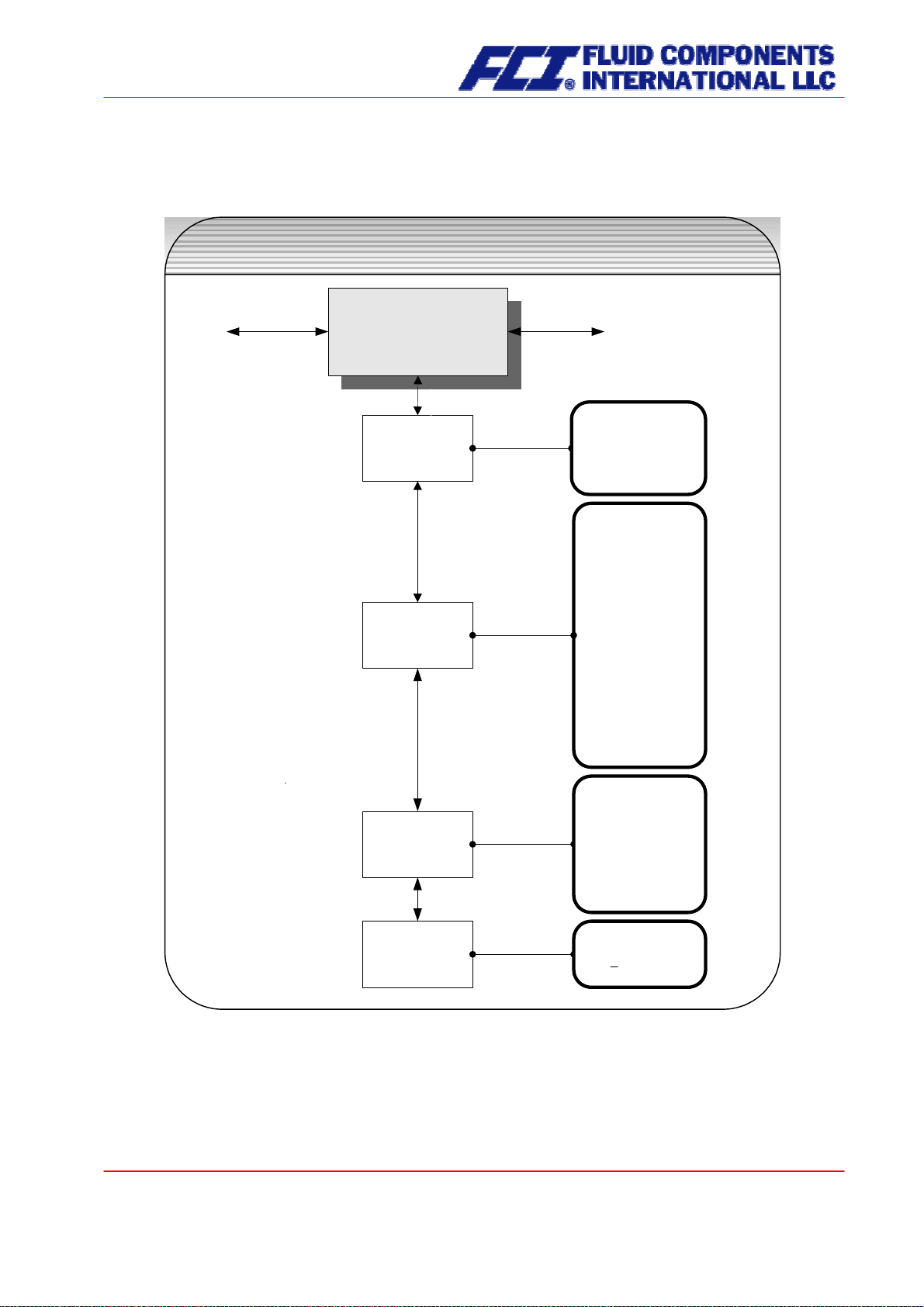
13.8 PULSE OUTPUT functional class
The PULSE OUTPUT functional class is comprised of the functions regarding the pulse output.
PULSE OUTPUT
functional class
PULSE OUTPUT
PULSE OUTPUT
Output of
Pulse or frequency
Pulse or frequency
output
output
Pulse output unit
Pulse output unit
[Pulses]
_______________
Pulses
Frequncy
Accumulation of
1.0 kg
______________
g
kg
t
m³
l
USG
UKG
USB
lbs
ston
lton
ft³
acft
1 pulse per
[1.0] unit
________________
0.001
Pulse value
Pulse value
Pulse width
Pulse width
0.01
0.1
1.0
10.0
100.0
Pulse width
0050.0 ms
13.8.1 Pulse or frequency output
The Pulse or frequency output function allows the operator to define whether pulses represent a unit of flow, i.e lbs, kg, USG, for totalizing or a frequency between 0 and 1 kHz that represents an analog output over the measuring range.
CMU & CT OPERATING MANUAL
Page 81 of 112
Part No 06EN003380 rev 1.6
Page 82

After selecting the frequency setting, the maximum frequency of 1 kHz will be generated when the upperrange value for mass or volume flow is reached (depending on the selected pulse unit). If the flow rate
falls below the low flow volume, the actual frequency is 0 Hz.
After selecting the pulse setting, pulse value and unit, the transmitter will determine the number of pulses
per flow volume. When choosing a combination of these settings that cannot be fulfilled in real time for
the upper-range value (e.g. the number of pulses per time unit cannot be generated due to the pulse
width which is too large), the error message “Pulse width too large” or “Inconsistent parameter” will be
displayed.
↵ to display the current setting:
Press
Output of
[Pulses]
According to the description in Section 12.4.3.1 Selection window/make a selection, the operator can
toggle between frequency and pulse output (default setting).
13.8.2 Pulse output unit
This function allows the operator to define the unit to be counted. After selecting the
function, press
↵ to display the following selection field:
Pulse output unit
Accumulation of
1.0 kg
The current value will be displayed. As mentioned in Section 12.4.3.2 Input window/modify a value, the
operator can choose between the following units:
Mass units:
g, kg, t, lbs, ston, lton
Volume units
m³, l, USG, UKG, USB, ft³, acft
13.8.3 Pulse value
This function allows the operator to define how many pulses will be output per unit counted. After selecting the
Pulse value function, press ↵ to display the current unit:
1 pulse per
[1.0] unit
As mentioned in Section 12.4.3.1 Selection window/make a selection, the operator can choose between
the following pulse values:
Values: 0.001, 0.01, 0.1, 1.0, 10.0, 100.0
Page 82 of 112
CMU & CT OPERATING MANUAL
Page 83

13.8.4 Pulse width
This function allows the operator to change the width of the output pulse. If the pulse width is too large for
the actual pulse number, it will be reduced automatically. In this case the warning “Pulse output saturated” will be displayed.
After selecting the
The current pulse width will be displayed. As mentioned in Section 12.4.3.2 Input window/modify a value,
the operator can change the current value.
The maximum output frequency can be calculated from the following formula:
If connecting to electrical counter relays, we recommend pulse widths greater than 4 ms; for electromechanical counter relays the preset value should be 50 ms.
Pulse width function, press ↵ to display the following selection field:
Pulse width
0050.0 ms
f 1000
1
≤=
mswidthpulse
][*2
Hz
CMU & CT OPERATING MANUAL
Part No 06EN003380 rev 1.6
Page 83 of 112
Page 84

13.9 STATUS functional class
The functional class STATUS is comprised of the functions for setting the status output.
STATUS
functional class
STATUS
STATUS
Output active
Status output
Status output
active state
active state
Status output 1
Status output 1
assignment
assignment
[closed]
_________________
closed
open
Output 1 assigned to
[Alarm]
________________
Forw. flow
Rev. flow
MIN QM
MAX QM
MIN density
MAX density
Alarm
IMP2 90°
Output 2 assigned to
Status output 2
Status output 2
assignment
assignment
Binary input
Binary input
assignment
assignment
[not avail.]
________________
Forw. flow
Rev. flow
MIN QM
MAX QM
MIN density
MAX density
Alarm
not avail.
Input assig. to
[not avail.]
________________
counter = 0!
set zero!
clr. errors
not avail.
only custody transfer
no standard
only custody transfer
no standard
Page 84 of 112
CMU & CT OPERATING MANUAL
Page 85

13.9.1 Status output active state
The status output can be compared to an electrical relay that can function as make or break contact. For
safety-relevant applications, the operator will choose the break contact setting so that a power failure or
failure of the electronics can be detected like an alarm. In standard applications, the output is used as
make contact.
Status output state active state function allows the operator to define the behavior of the status out-
The
put.
Status output active
[closed]
As mentioned in Section 12.4.3.1 Selection window/make a selection, the operator can choose between
the following settings:
¾ closed
¾ open
13.9.2 Status output 1 assignment
This function allows the operator to define to which event the status output is to be assigned. The most
general assignment is the alarm assignment because all set limiting values and the self-test function are
then monitored via the status output.
After selecting the
Status output assignment function, press ↵ to display the current assignment.
Output 1 assigned to
[Alarm]
As mentioned in Section 12.4.3.1 Selection window/make a selection, the operator can choose between
the following settings:
¾ Flow direction recognition
o Forward flow
o Reverse flow
¾ Limiting values:
o MIN QM
o MAX QM
o MIN density
o MAX density
¾ All limiting values and error detection
o Alarm
¾ Pulse output 2 for custody transfer operations
o IMP2 90°,
When selecting the IMP2 90° setting, a second pulse output will be realized via the status output that can
be used for custody transfer operations.
CMU & CT OPERATING MANUAL
Part No 06EN003380 rev 1.6
Page 85 of 112
Page 86

13.9.3 Status output 2 assignment
Instead of current output 2 there is another status output available for custody transfer operations.
It has the same assignment possibilities as status output 1. However, it cannot be used as pulse output.
After selecting the
Status output assignment function, press ↵ to display the current assignment.
Output 2 assigned to
[not available]
As mentioned in Section 12.4.3.1 Selection window/make a selection, the operator can choose between
the following settings:
¾ Standard setting
o Not available
¾ Flow direction recognition:
o Forward flow
o Reverse flow
¾ Limiting values
o MIN QM
o MAX QM
o MIN density
o MAX density
o Alarm all limiting values and error detection
13.9.4 Binary input assignment
For the custody transfer operations version, instead of current output 2 there is an additional input available for connecting an external pushbutton.
This pushbutton is assigned the following functions:
o Pressing the button for a short moment: display test
o Pressing the button for more than 5 seconds: error reset
Input assigned to
[Reset error]
The pushbutton may be assigned other functions for non-custody transfer operations. After selecting the
Input is released function, press
↵ to display the current assignment.
Input assigned to
[Not available]
According to the description in Section 12.4.3.1 Selection window/make a selection, one of the following
assignments can be selected:
• Standard setting:
o Not available
• Others:
o Counters = 0, i.e. reset counters to zero.
o Zero point, i.e. carry out zero point calibration
o Reset error, i.e. acknowledge error messages
Page 86 of 112
CMU & CT OPERATING MANUAL
Page 87

13.10 CURRENT OUTPUTS functional class
The CURRENT OUTPUT functional class allows the operator to perform the settings for the current outputs of the transmitter.
CURRENT OUTPUTS
functional class
CURRENT OUTPUTS
CURRENT OUTPUTS
using HART:
I1 always 4 - 20,5mA or
4 - 21,6mA
Curr. output I1
Curr. output I1
0/4 - 20 mA
0/4 - 20 mA
Curr. output I1
Curr. output I1
alarm
alarm
Curr. output I1
[4 - 21,6mA]
_______________
0 - 21,6 mA
4 - 21,6 mA
4 - 20,5 mA
I1: alarm
[>22mA]
_______________
<3.8mA
>22 mA
not used
using HART:
standard I1: mass flow
Curr. output I1
Curr. output I1
assignment
assignment
Curr. output I2
Curr. output I2
0/4 - 20 mA
0/4 - 20 mA
Curr. output I2
Curr. output I2
alarm
alarm
Curr. output I2
Curr. output I2
assignment
assignment
I1 assigned to
[Mass flow.]
______________
Mass flow.
Volume flow.
Density
Temperature
Curr. output I2
[4 - 21,6mA]
_______________
0 - 21,6 mA
4 - 21,6 mA
4 - 20,5 mA
I2: alarm
[not used]
_______________
<3.8mA
>22 mA
not used
I2 assigned to
[Temperature]
______________
not used
Mass flow
Volume flow
Density
Temperature
CMU & CT OPERATING MANUAL
Page 87 of 112
Part No 06EN003380 rev 1.6
Page 88

13.10.1 Current output I1 0/4 to 20 mA
The Current output I1 0/4 to 20 mA function allows the operator to define the range in which the current output is to be operated. Within the range from 0 to 21.6 mA (= 0 ... 110 %)
HART communication® is not
possible. The range from 4 to 20.5 mA follows the NAMUR recommendation and covers the range from 0
to 104 % of the measuring range. The standard range from 4 to 21.6 mA allows for a control of the measuring range of up to 110 %.
↵ to display the current setting.
Press
Current output I1
[4] – 21.6 mA
As mentioned in Section 12.4.3.1 Selection window/make a selection, the operator can choose between
the following settings:
Current output
25,00 mA
20,00 mA
15,00 mA
10,00 mA
Output current
5,00 mA
0,00 mA
0% 20% 40% 60% 80% 100% 120%
Measured value
0 - 20 (21,6) mA 4 - 20,5 mA
NAMUR
4 - 21,6 mA
Standard
13.10.2 Current output I1 alarm
This function allows the operator to define the state taken on by the current output when a state of alarm
is detected. This information can be analyzed in the control system. Press
↵ to display the current setting:
I1 : alarm
[>22mA]
As mentioned in Section 12.4.3.1 Selection window/make a selection, the operator can choose between
the following settings:
¾ not used no alarm function
¾ > 22 mA current rise in the case of an alarm
¾ < 3.8 mA current reduction in the case of an alarm
13.10.3 Current output I1 assignment
Page 88 of 112
CMU & CT OPERATING MANUAL
Page 89

This function allows the operator to define the measured value to be output as an analog signal via current output I1. When devices with HART
ally assigned to mass flow. Press
®
communication capabilities are used, current output I1 is usu-
↵ to display the current setting.
I1 assigned to
[Mass flow]
As mentioned in Section 12.4.3.1 Selection window/make a selection, the operator can choose between
the following settings:
¾ Mass flow
¾ Volume flow
¾ Density
¾ Temperature
13.10.4 Current output I2 0/4 to 20 mA
Current output I2 0/4 to 20 mA function allows the operator to define the range in which the current
The
output is to be operated. The range from 4 to 20.5 mA follows the NAMUR recommendation and covers
the range from 0 to 104 % of the measuring range. The standard range from 4 to 21.6 mA allows for a
control of the measuring range of up to 110 %.
Press
↵ to display the current setting.
Current output I2
[4] – 21.6 mA
As mentioned in Section 12.4.3.1 Selection window/make a selection, the operator can choose between
the following settings:
CMU & CT OPERATING MANUAL
Page 89 of 112
Part No 06EN003380 rev 1.6
Page 90

13.10.5 Current output I2 alarm
This function allows the operator to define the state taken on by the current output when a state of alarm
is detected. This information can be analyzed in the control system. Press
↵ to display the current setting.
I2 : alarm
[not used]
As mentioned in Section 12.4.3.1 Selection window/make a selection, the operator can choose between
the following settings:
¾ not used no alarm function
¾ > 22 mA current rise in the case of an alarm
¾ < 3.8 mA current reduction in the case of an alarm
13.10.6 Current output I2 assignment
This function allows the operator to define the measured value to be output as an analog signal via current output I2. Press
↵ to display the current setting.
I2 assigned to
[Temperature]
As mentioned in Section 12.4.3.1 Selection window/make a selection, the operator can choose between
the following settings:
¾ Mass flow
¾ Volume flow
¾ Density
¾ Temperature
¾ not available (in this case the vendor setting must not be changed)
Page 90 of 112
CMU & CT OPERATING MANUAL
Page 91
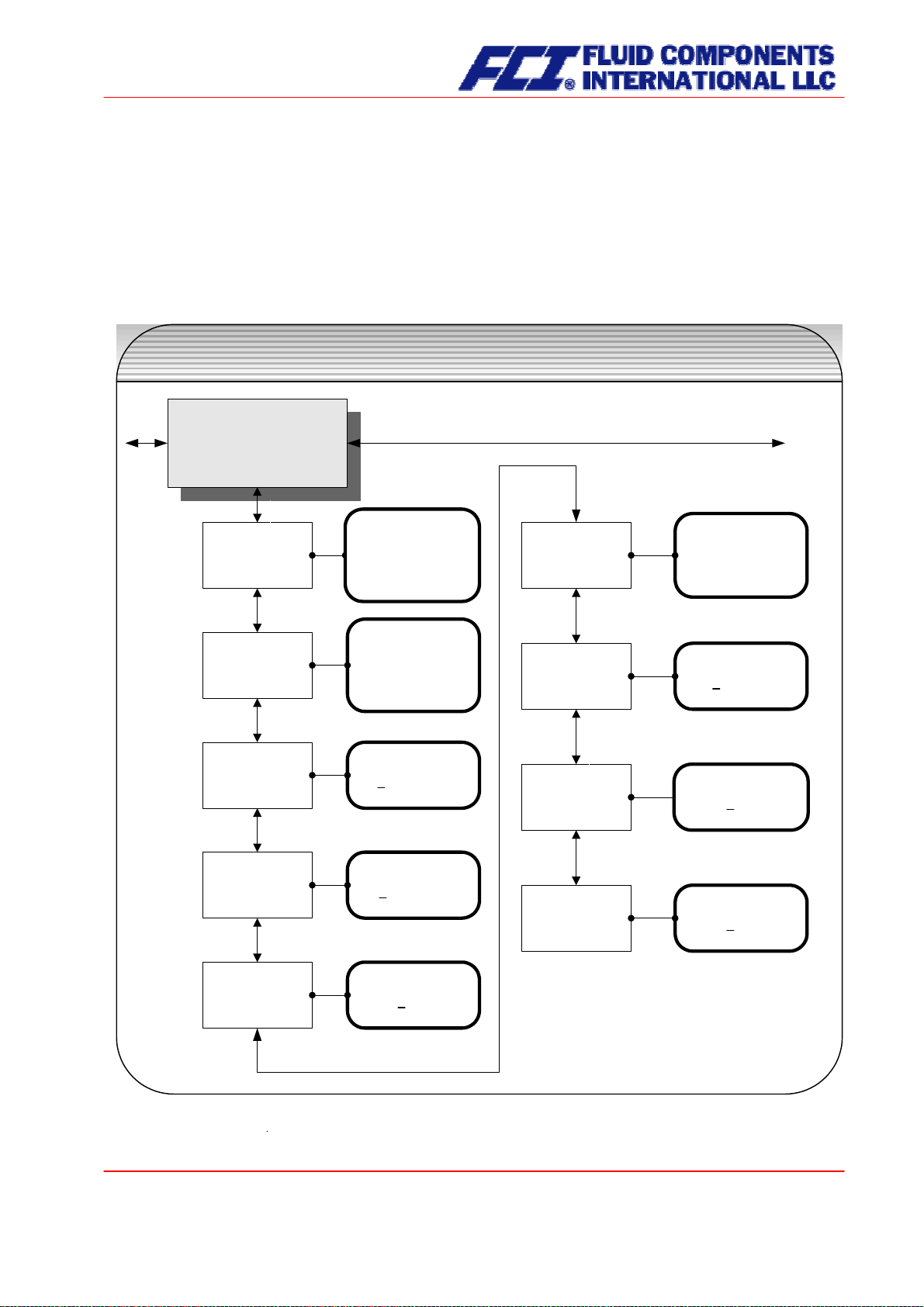
13.11 SIMULATION functional class
The functional class SIMULATION is comprised of the functions for simulating the outputs. If simulation is
activated, all output signals will be generated based on the selected type of simulation. The peripherals
connected to the device can be tested without a flowing product.
Simulation will be deactivated automatically if the operator switched the device off or did not touch any
control unit keys for about 10 minutes. Simulation can also be activated and controlled via HART
®
com-
mands.
SIMULATION
functional class
SIMULATION
SIMULATION
Simulation
Simulation
on / off
on / off
Simulation
Simulation
direct / QMabs
direct / QMabs
Simulation
Simulation
QMabs
QMabs
Simulation
Simulation
density
density
Simulation
[off]
_________________
on
off
Simulation
[direct]
_______________
direct
QM, D, T
Set QMabs
+0900.000 kg/h
Set density
0500.000 g/l
Simulation
Simulation
status output
status output
Simulation
Simulation
pulse output
pulse output
Simulation
Simulation
curr. output I1
curr. output I1
Simulation
Simulation
curr. output I2
curr. output I2
Status output
[on]
_________________
on
off
Set frequency
0009.0 Hz
Set I1
I1 = 12.00 mA
Set I2
I2 = 12.00 mA
Simulation
Simulation
temperature
temperature
Set temperature
+090 °C
CMU & CT OPERATING MANUAL
Page 91 of 112
Part No 06EN003380 rev 1.6
Page 92

13.11.1 Simulation on/off
Simulation on/off function allows the operator to activate or deactivate simulation. If simulation is
The
activated, all output signals will be generated based on the selected type of simulation. The peripherals
connected to the device can be tested without a flowing product. Press
↵ to display the current status.
Simulation
[off]
As mentioned in Section 12.4.3.1 Selection window/make a selection, the operator toggle between the
“on” and “off.”
Simulation will be deactivated automatically if the operator switched the device off or did not touch any
control unit keys for about 10 minutes.
13.11.2 Direct simulation
This function allows the operator to define whether simulation is comprised of the measurement of the
three physical values mass flow, density and temperature or whether the outputs will be set directly.
Press
↵ to display the selected type of simulation.
Simulation
[direct]
As mentioned in Section 12.4.3.1 Selection window/make a selection, the operator can choose between
the following settings:
¾ Direct pulse and current outputs are programmed directly
¾ QM, D, T a measurement is simulated
If “direct” simulation is activated, any output will perform based on the settings described in Sections
13.11.4.1 Status output simulation to 13.11.4.4 Simulation current output I2. It is therefore recommended
that the settings be defined before starting simulation. They can then be purposefully changed during
simulation.
The status of the outputs during measured value simulation based on the setting “QM, D, T” depends on
the selected simulation values of these three variables, the measuring range settings and the assignment
of the outputs. If, for example, the pulse output is assigned to volume measurement, it will be affected by
all three simulation values at the same time [V ≈ QM (T) / D (T)].
Simulation will be deactivated automatically if the operator switched the device off or did not touch
any control unit keys for about 10 minutes.
Page 92 of 112
CMU & CT OPERATING MANUAL
Page 93

13.11.3 Measured value simulation
If the operator selected the setting “QM, D, T” described in Section 13.11.2 on page 92, the following
three possible settings will affect the output behavior during measured value simulation, where all measured values are simulated at the same time.
13.11.3.1 Simulation mass flow QM abs
In order to simulate mass flow, the operator can define a “measured value.” The flow rates will be simulated in both directions. All outputs will perform based on the simulated measured value.
Set QM abs
±0900.0 kg/h
The simulation value is entered as described in Section 12.4.3.2 Input window/modify a value.
13.11.3.2 Density simulation
In order to simulate density/volume measurement, the operator can define a “density measured value.” If
volume measurement is assigned to an output, it will change depending on mass flow and density simulation. All outputs will perform based on the simulated measured value.
Set density
0500.0 g/l
The simulation value is entered as described in Section 12.4.3.2 Input window/modify a value.
13.11.3.3 Temperature measurement simulation
In order to simulate a temperature, the operator can define a “measured value.” All outputs will perform
based on the simulated measured value.
Set temperature
+090 °C
The simulation value is entered as described in Section 12.4.3.2 Input window/modify a value.
CMU & CT OPERATING MANUAL
Part No 06EN003380 rev 1.6
Page 93 of 112
Page 94

13.11.4 Direct simulation of outputs
If the operator selected the setting “Direct simulation” described in Section 13.11.2 Direct simulation on
page 92, the following four possible settings will affect the output behavior during measured value simulation, where all measured values are simulated at the same time.
13.11.4.1 Status output simulation
Status output simulation function allows the operator to purposefully activate the status output.
The
Press
↵ to display the current state.
Status output
[off]
As mentioned in Section 12.4.3.1 Selection window/make a selection, the operator can toggle between
“on” and “off.”
13.11.4.2 Pulse output simulation
Pulse output simulation function allows the operator to define a frequency to be assigned to the pulse
The
output. After selecting this function and pressing
↵, the following selection field will be displayed:
Set frequency
0210.0 Hz
This field shows the current frequency. As mentioned in Section 12.4.3.2 Input window/modify a value,
the definable frequency ranges from 6 Hz to 1100 Hz.
13.11.4.3 Simulation current output I1
This function allows the operator to define a current for current interface 1. Press
↵ to display the set
current.
Set I1
I1 = 10.50 mA
As mentioned in Section 12.4.3.2 Input window/modify a value, the current value can be changed.
13.11.4.4 Simulation current output I2
As described in Section 13.11.4.3, current output 2 can also be configurated.
Page 94 of 112
CMU & CT OPERATING MANUAL
Page 95
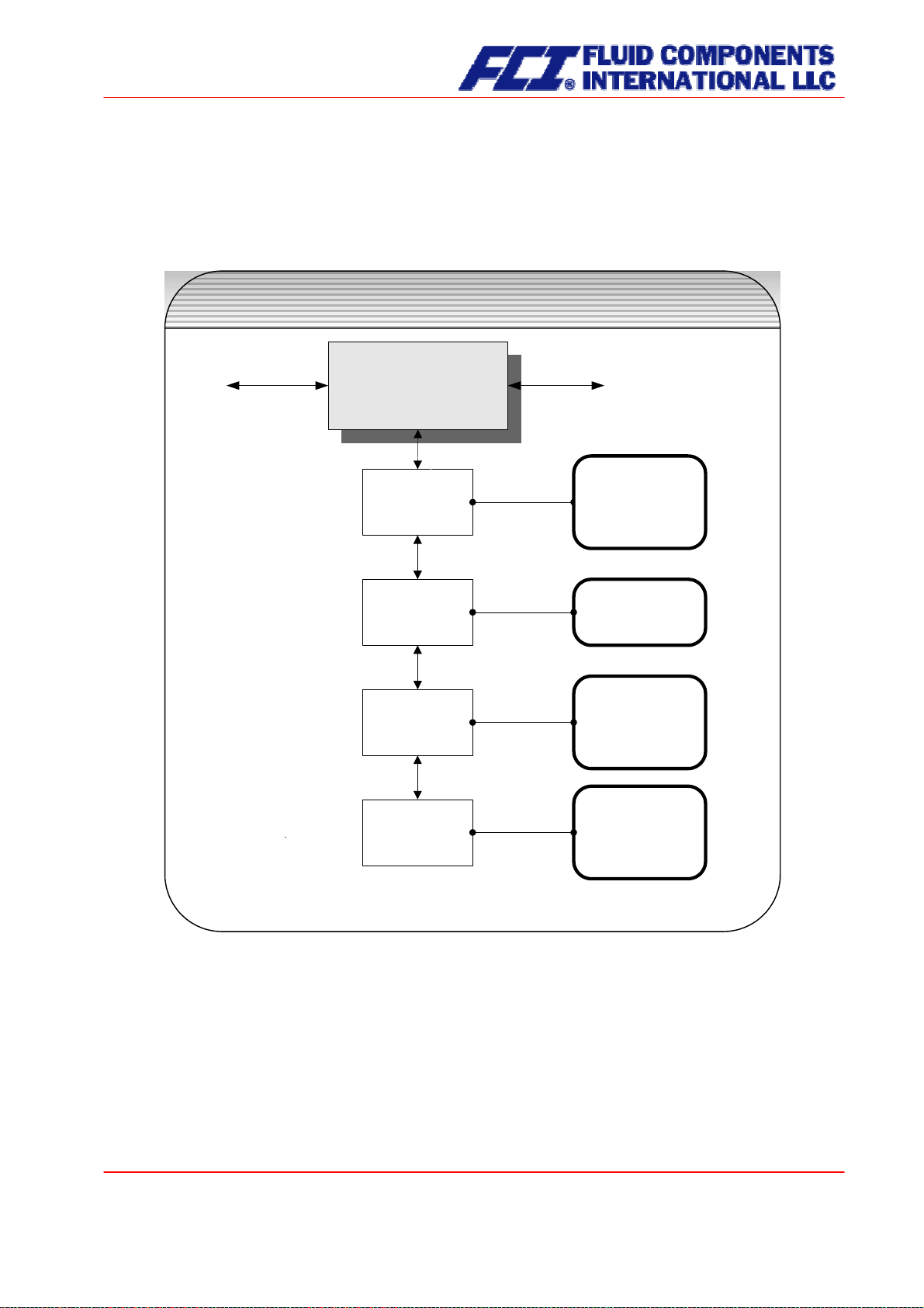
13.12 SELF-TEST function class
The SELF-TEST function class is comprised of the functions relating to the self-test of the sensor.
The diagnostic functions of the transmitter, which monitor the proper functioning of the electronics and
the software, are always active and cannot be switched off. The excitation current can be monitored in
addition.
SELF-TEST
functional class
SELF-TEST
SELF-TEST
Sensor test
Sensor test
Sensor test
on / off
on / off
[off]
_______________
off
on
Max. deviation of
Max. deviation of
excitation
excitation
Self-test
Self-test
calibration
calibration
Monitoring
Monitoring
sensor
sensor
Max. deviation
020 %
Calibration
[no]
_______________
no
yes
S1 7749 S2 7812
E 1280
The excitation current of each sensor in the system individually depends on the sensor itself, the fluid and
the installation conditions. If the excitation currents changes while the fluid remains the same, conclusions may be drawn for e.g. potential wear and tear, viscosity changes or air bubbles. The operator has
the possibility of defining a “normal state” (“Self-test calibration”) and setting the limit for a permissible
deviation. This function is deactivated in the device when delivered.
CMU & CT OPERATING MANUAL
Page 95 of 112
Part No 06EN003380 rev 1.6
Page 96

13.12.1 Sensor test on/off
Sensor test on/off function allows the operator to activate or deactivate the monitoring function of the
The
excitation current.
Sensor test
[off]
According to the description in Section 12.4.3.1 Selection window/make a selection, the operator can
toggle between “on” and “off.” The standard factory setting is “off.”
13.12.2 Max. deviation of excitation
This function allows the operator to define a limiting value in the form of a percentage deviation from the
normal value. The excitation current is electronically limited to 50 mA (display value 500) and may take
on larger values for only a limited period of time (transient reactions).
Max. deviation
020 %
The current limiting value is displayed. As mentioned in Section 12.4.3.2 Input window/modify a value, the
value can be changed taking into account permissible fluctuations.
13.12.3 Self-test calibration
Since the quantity of the excitation current does not only depend on the sensor itself but also on the installation conditions and the viscosity and density of the fluid, the normal value can only be calculated on
site during operation using the
Self-test calibration function.
Calibration
[no]
If the operator toggles to [yes] according to the description in Section 12.4.3.1 Selection window/make a
selection, the normal value will be calculated automatically. No additional information is needed for this
function.
13.12.4 Monitoring of sensor amplitude and excitation current
This first line of this window contains the amplitudes of the sensor signals S1 and S2 in 10 µV. Both values should be close to each other or identical (ideal case). The second line shows the excitation current
in 10 µA units.
S1 7749 S2 7812
E 1280
Example: The sensors have an amplitude of 77.49 mV and 78.12 mV. The excitation current is 12.8 mA.
Page 96 of 112
CMU & CT OPERATING MANUAL
Page 97

13.13 UMC TRANSMITTER SETTINGS functional class
This functional class is comprised of the general settings (e.g. language) affecting the behavior of the
transmitter.
Transmitter SETTINGS UMC3
functional class
SETTINGS UMC
SETTINGS UMC
Language
Language
Language
[German]
________________
German
English
Serial number
Serial number
Software version
Software version
UMC
UMC
BE 2.x
BE 2.x
Reset
Reset
system error
system error
Device address
Device address
Profibus / Modbus
Profibus / Modbus
Serial number
123456
UMC-Rev. 1.78
EECS 78E3 CS 78E3
Reset error
[no]
_______________
yes
no
Device address
126
CMU & CT OPERATING MANUAL
Page 97 of 112
Part No 06EN003380 rev 1.6
Page 98

13.13.1 Language
Two languages are available in the control unit BE2: English and German. As mentioned in Section
12.4.3.1 Selection window/make a selection, the operator can toggle between these languages.
Language
[English]
Other languages such as French, Italian or Spanish will be available in a special version of the control
unit BE2.
13.13.2 Serial number
With the help of the
Serial number function, the transmitter is assigned to an order. This number provides
access to internal vendor data if the device needs servicing. The serial number is printed on the rating
plate of the transmitter. After selecting this function, press
↵ to display the following information field:
Serial number:
100683
This entry should never be changed so as to ensure that the sensor, the transmitter and the documents
created within quality management are assigned correctly.
13.13.3 Software version
When the function
Software version is displayed, the software version of the control unit BE will be
shown. Example: Version 2.0:
UMC Software
Version BE 2.0
After selecting this function, the version of the transmitter software will be shown (example: 1.78).
UMC Rev.: 1.78
EECS 78E3 CS 78E3
The second line contains the hexadecimal checksum that was calculated via the program storage created
during program development and the microcontroller checksum of the same storage. Both checksums
must be identical, when the program storage has not been damaged.
13.13.4 Reset system error
The integrated diagnostic system of the CT transmitter distinguishes between two types of errors (see
also Section 15 CT transmitter error messages). Self-test errors such as problems with a sensor line or
inconsistent parameter inputs are displayed as textual error messages. Once the error has been eliminated, the message automatically disappears from the display. For further information, see Section 15.3.1
Display of self-test errors.
Page 98 of 112
CMU & CT OPERATING MANUAL
Page 99

Errors that are attributable to system memory or software, division by zero, or a fault in the electronics
unit are designated as system errors. These error messages are not reset automatically after the error
(usually of very brief duration) is eliminated.
you contact our technical service department.
Before resetting a system error manually, we advise that
For further information, see Section 15.3.1 Display of
self-test errors.
Reset error
[no]
If the operator toggles to [yes] and confirms the action according to the description in Section 12.4.3.1
Selection window/make a selection, the error messages disappears from the display. If the message
reappears shortly after, do contact our technical service department.
13.13.5 Profibus/Modbus device address
Before connecting fieldbus devices to a bus system, the operator must define a device address. This
address is a unique assignment to a participant device in a bus system (similar to a street number).
After selecting the
Profibus/Modbus device address, press ↵ to display the set address:
Device address
126
As mentioned in Section 12.4.3.2 Input window/modify a value, the operator can change the displayed
value. After setting the new device address, press
↵ to confirm and apply the change.
CMU & CT OPERATING MANUAL
Part No 06EN003380 rev 1.6
Page 99 of 112
Page 100
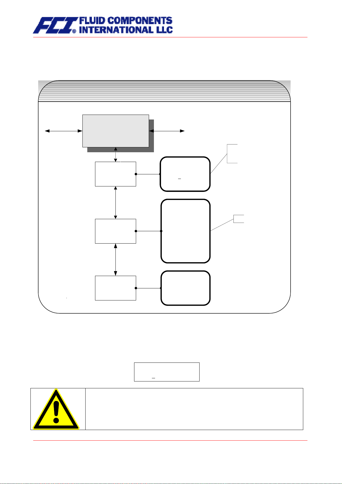
13.14 SENSOR SETTINGS functional class
The SENSOR SETTINGS functional class is comprised of the settings regarding the mass flow sensor.
SENSOR SETTINGS
functional class
SENSOR SETTINGS
SENSOR SETTINGS
set by manufacturer
change only after re-
calibration (custody transfer)
Sensor
Sensor
constant C
constant C
Flow tube material
Flow tube material
Flow direction
Flow direction
Sensor constant
+0150.00
Flow tube
of [1.4571]
_______________
1.4571
1.4301
HC 4
HB 2
Tantal
Titan
Nickel
Special
Flow direction
[forward]
_______________
forward
reverse
forw. & revers
set by manufacturer
13.14.1 Sensor constant C
Sensor constant C is the sensor calibration value for mass flow. This constant is defined when the flowmeter is calibrated at the factory and can be found on the rating plate.
Sensor constant
+0150.00 kg/h
CAUTION:
Changing sensor constant C to a value that differs from the value on the rating plate
of the sensor connected to the flowmeter will result in false readings.
Page 100 of 112
CMU & CT OPERATING MANUAL
 Loading...