

Page 1
Fluid Components Intl
7. Commissioning
7.1 Keypad and display
layout
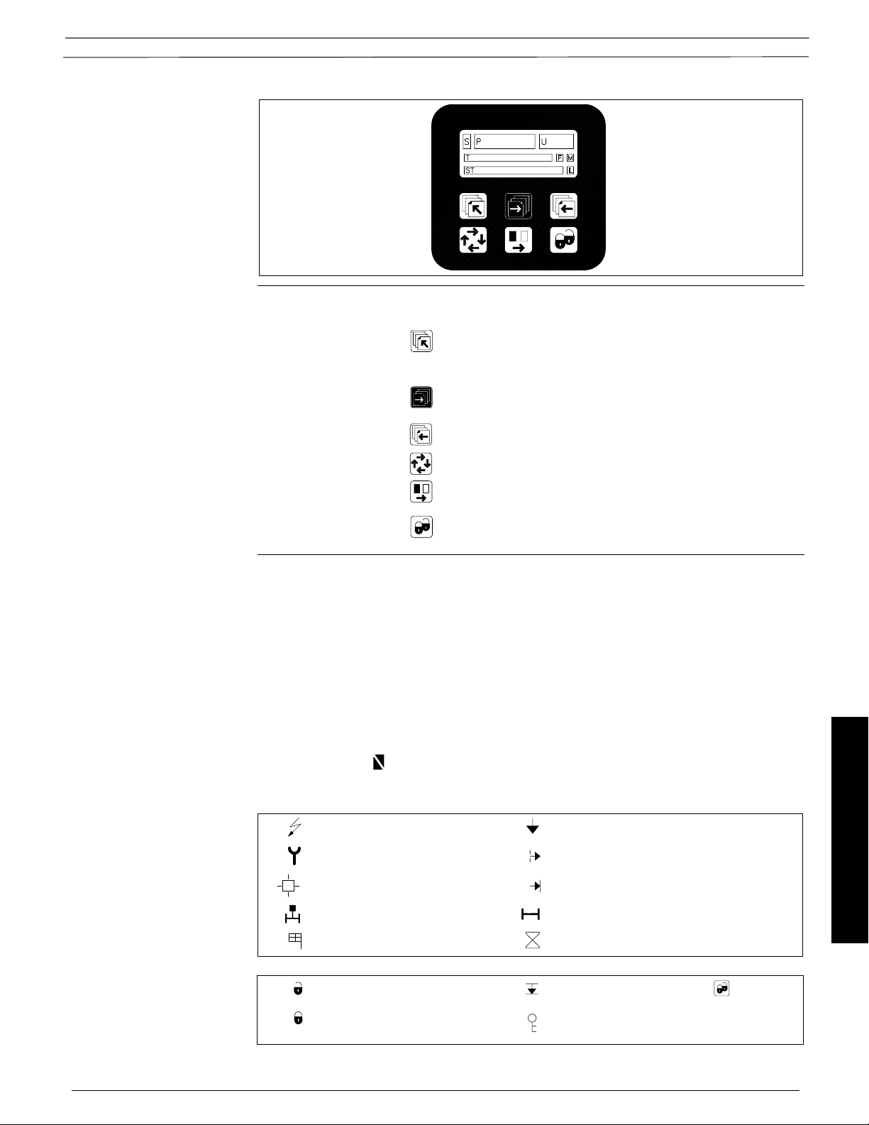
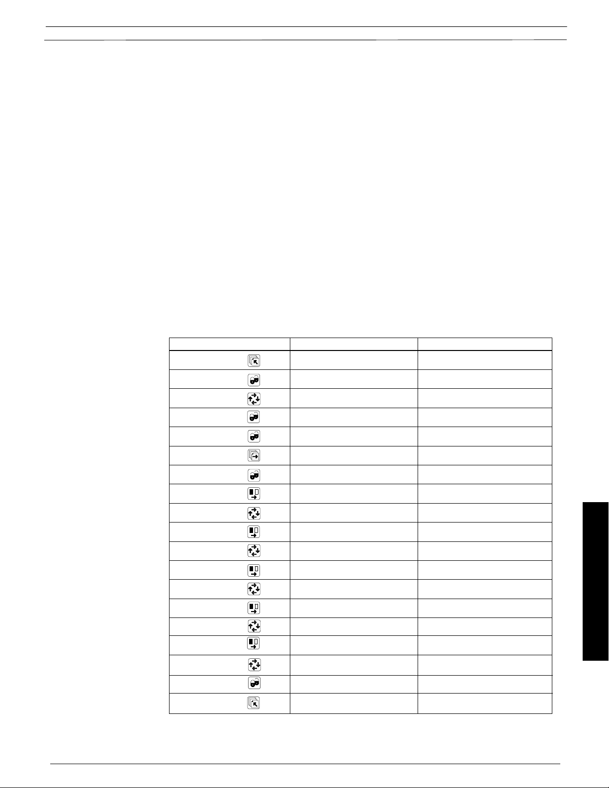
Keypad The keypad is used to set the flowmeter. The function of the keys are as follows:
Display
TOP UP KEY This key (hold 2 sec.) is used to switch between operator
menu and setup menu. In the converter setup menu, a short
press will cause a return to the previous menu.
FORWARD KEY This key is used to step forward through the menus. It is the
only key normally used by the operator.
BACKWARD KEY This key is used to step backward through the menus.
CHANGE KEY This key changes the settings or numerical values.
SELECT KEY This key selects the figures to be changed.
LOCK/UNLOCK KEY This key allows the operator to change settings and gives
access to submenus.
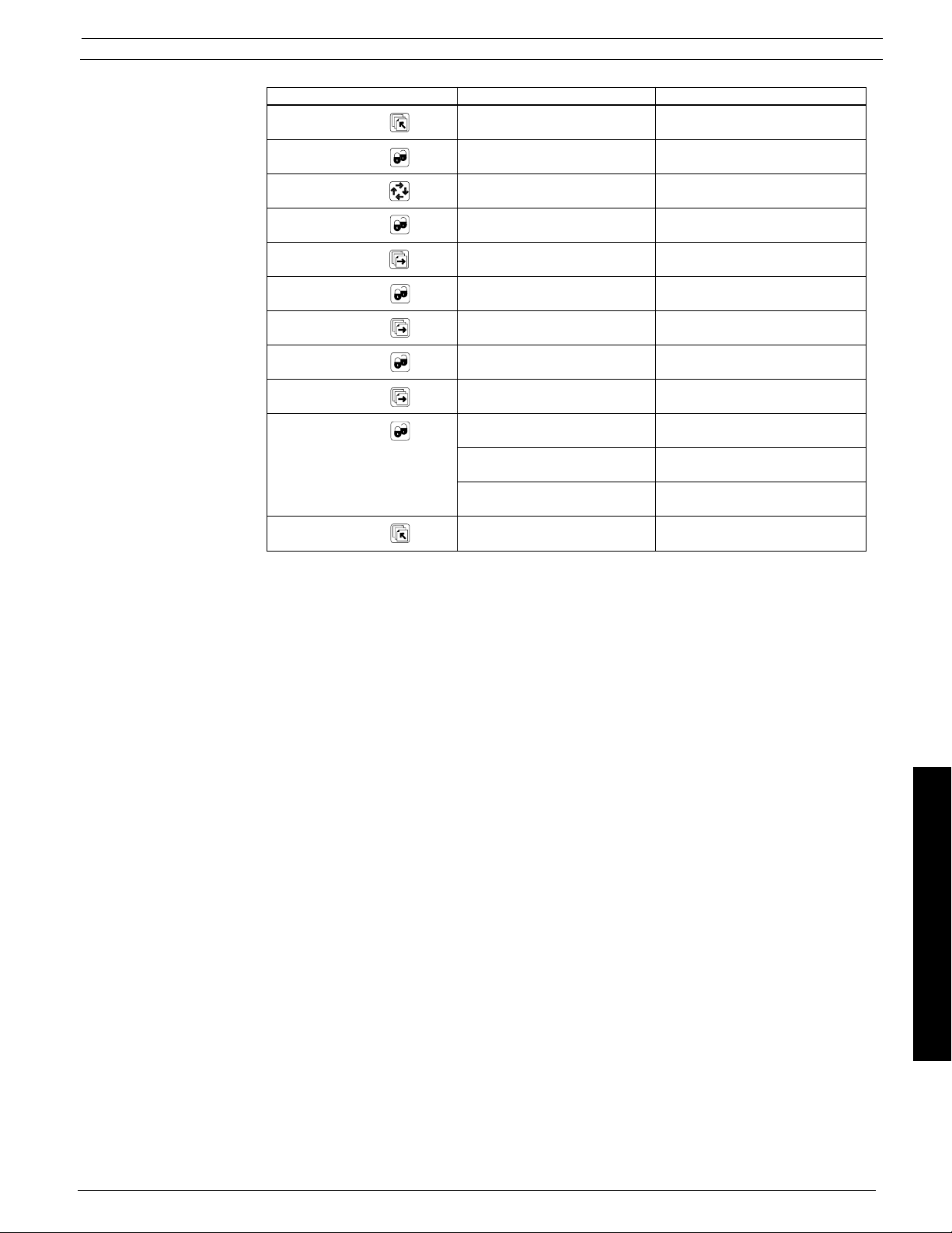
The display is alphanumerical and indicates flow values, flowmeter settings and error messsages.
The upper line is for primary flow readings and will always show either mass flowrate, volume
flowrate, density, temperature, totalizer 1 or totalizer 2. The line is divided into 3 fields.
S: Sign field
P: Primary field for numerical value
U: Unit field
The center line is the title line (T) with individual information according to the selected operator or
setup menu.
The lowest line is the subtitle line (ST) which either will add information to the title line or keep
individual information independent of the title line.
Document 06EN003327 Rev. -
F: The alarm field. Two flashing triangles will appear by a fault condition.
M: The mode field. The symbols indicate the following.
Communication mode Basic settings
Service mode Output
Operator menu External input
Product identity Sensor characteristic
Language mode Reset mode
L: The lock field. Indicates the function of the lock key.
Ready for change Access to submenu (Press )
Value locked RESET MODE: Zero setting of
51 FlexCOR
totalizers and initialization of setting
™ Model CMF Series
Commissioning
Page 2
Fluid Components Intl
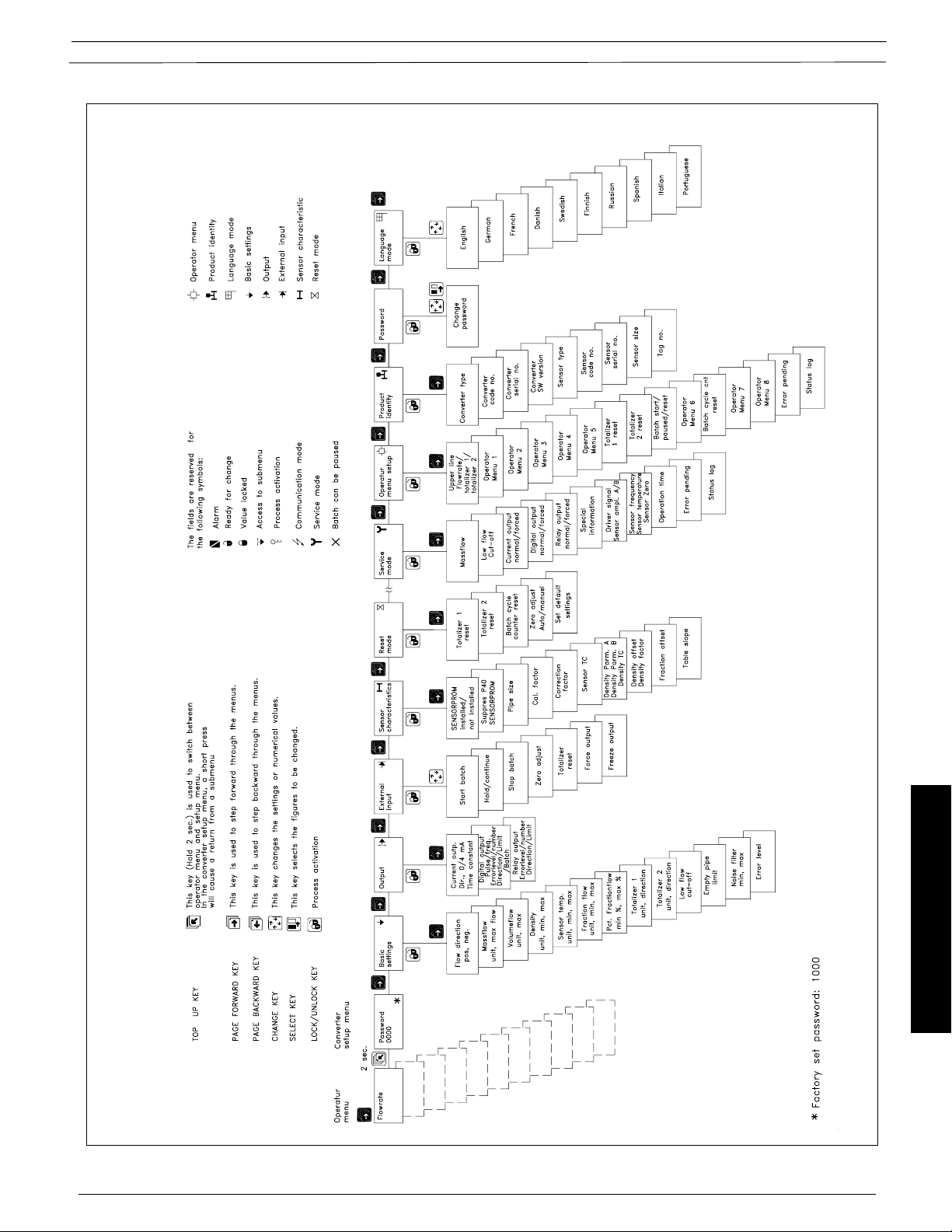
7.2 Menu build-up
The menu structure of a specific type of transmitter is shown in a menu overview map.
Details of how a specific parameter is set is shown in a menu detail map for the specific parameter.
The menu structure is valid for the title and subtitle line only. The upper line is for primary readings
only and will always be active with either mass flow rate, volume flowrate, density, temperature,
totalizer 1 or totalizer 2.
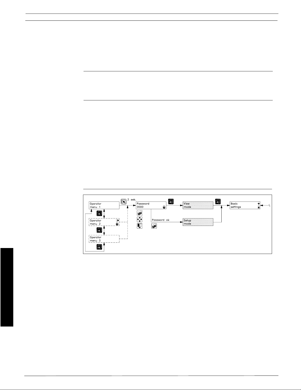
The menu is built up in two parts. An operator menu and a setup menu.
Operator menu
The operator menu is for daily operation. The operator menu is customized in the operator menu
setup. The signal converter always starts in the operator menu no. 1. The page forward and page
backward keys are used to step through the operator menus.
Setup menu
The setup menu is for commissioning and service only.
The setup menu is accessed by pressing the top up key for 2 seconds. The setup menu will operate
in two modes:
- View mode
- Setup mode
View mode is a read only mode. The pre-selected settings can only be scanned.
Setup mode is a read and write mode. The pre-selected settings can be scanned and changed.
Access to the setup mode is protected with a password. The factory set password is 1000.
Access to a submenu in the set up menu is gained by the lock key. A short press on the top up key
will bring back the previous menu. A long press (2 sec.) on the top up key will exit the setup menu
and bring back the operator menu no. 1.
7.2.1 Password
Commissioning
The SETUP MENU can be operated in two different modes:
VIEW MODE (Read only)
CHANGE MODE (Read and write mode)
The view mode is always accessed by pressing the forward key when in the password menu.
Access to change mode is protected by a user code. The user code is factory set to 1000, but can
be changed to any value between 1000 and 9999 in the change password menu.
The factory setting of 1000 can be re-established as follows:
- Switch off power suppply
- Press the TOP UP key while switching on the power supply
The user code is reset to 1000.
FlexCOR™Model CMF Series 52
Document 06EN003327 Rev. -
Page 3
Fluid Components Intl
Document 06EN003327 Rev. -
53 FlexCOR
Commissioning
™ Model CMF Series
Page 4
Fluid Components Intl
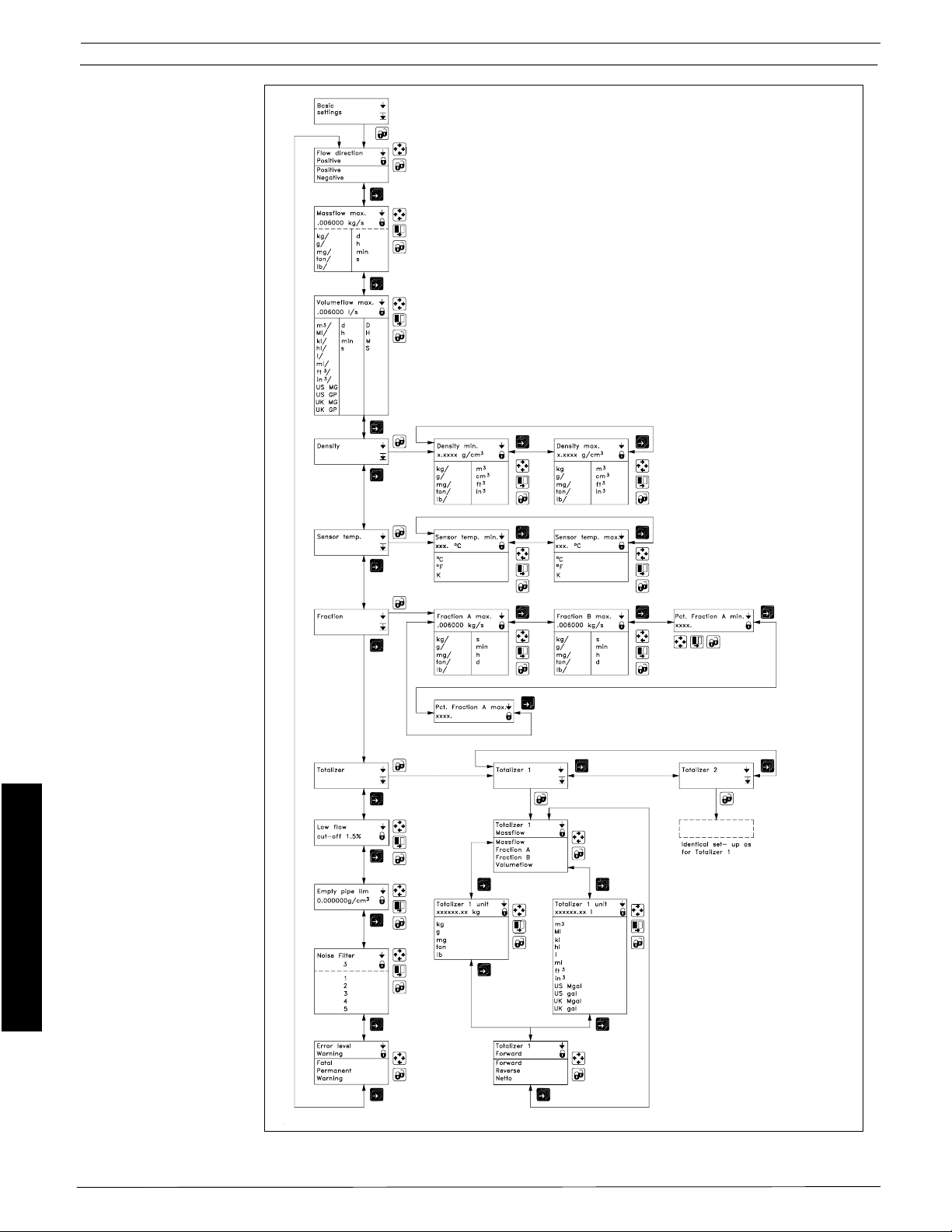
7.4 Basic settings
Menu detail
Commissioning
FlexCOR™Model CMF Series 54
Document 06EN003327 Rev. -
Page 5
Fluid Components Intl
Basic settings
Menu description
Setting of min./max.
values and units
Example; programming
of max. mass flow
The basic setting menu is used for basic configuration of the mass flow meter with a choice of units,
minimum and maximum limits for display and analog/digital outputs for all measurement
parameters, i.e. mass flow, volume flow, fraction, temperature and density.
Numerical values are entered by placing the cursor in the field that is to be set using the SELECT
key. Press unlock and the value can be changed using the change key. The desired value is locked
by activating LOCK.
Positioning of the decimal point is carried out by placing the cursor below the decimal point using
the SELECT key. The position can be set using the set key. The LOCK key is activated and the
decimal point is now positioned.
Selecting the unit: Place the cursor below the unit using SELECT key. Set the desired unit using
CHANGE key. Activate the LOCK key to save the setting. Place the cursor below the time scale
using SELECT key and choose the desired time scale using CHANGE, then save the desired value
by activating the LOCK key.
The maximum and minimum values set will then apply to all current and frequency/pulse outputs,
e.g. where the min. value will correspond to 0/4 mA depending on the setting of the current output
and the max. will correspond to 20 mA.
As example we want to change the default setting of the maximum mass flow on a CMF-A from
20 Kg/h to .45 lb/min.
Keypad operation Implementation Display on Transmitter
Push for 2 sec. To access the Password
user password 0000
Push once To unlock password CHANGE
0000
Push once To enter 1000 as CHANGE
password 1000
Push once To lock password and to CONV.SETUP MODE>
enter the menu Basic settings
Push once To enter basic setting Flow direction
submenu Positive
Push once To go to mass flow Massflow max.
max. setting 000020. kg/h
Push once To change num. Massflow max.
value 000020. kg/h
Push 4 times To move the cursor Massflow max.
to the num. position 000020. kg/h
Push Until 4 appears Massflow max.
000040. kg/h
Push once To move the cursor to Massflow max.
the next num. position 000040. kg/h
Push Till 5 appears Massflow max.
000045. kg/h
Push once To move the cursor to Massflow max.
the decimal point 000045. kg/h
Push To position the decimal Massflow max.
point correct 0000.45 kg/h
Push 3 times To move cursor Massflow max.
to "Kg" unit 0000.45 kg/h
Push twice To change units to lb. Massflow max.
0000.45Lb/h
Push once To move cursor to Massflow max.
the "h" unit 0000.45Lb/h
Push 3 times To change "h" to "min" Massflow max.
0000.45 Lb/min
Push To lock the new setting Massflow max.
of the mass flowmeter 000.45 Lb/m
Push twice Transmitter reverts to
standard operation
Commissioning
Document 06EN003327 Rev. -
55 FlexCOR
™ Model CMF Series
Page 6

Fluid Components Intl
Setting the totalizer
Setting the low-flow cut-off
Setting the empty pipe limit
Setting the noise filter
Setting the error level
The instrument is equipped with two independent totalizers that can be set for totalizing mass flow,
fraction A, faction B or volume.
Forward: only flow in a positive direction is totalized.
Reverse: only flow in a negative flow direction is totalized.
Net: the total net flow is measured.
In certain applications flow signals are not required below a given flow. In this menu a
0 to 10% cut-off of the maximum flow can be selected. By default the meter is set to 1.5%.
If detection of an empty pipe or of a density value is needed, it can be set under this menu option.
If the set density value is measured this will activate a relay or the digital output. In addition will
be recorded in the error log.
The instrument carries out signal processing internally using a patented FFT (Fast Fourier
Transformation) algorithm. This technology allows noisy sensor signals to be filtered. For
example, if the instrument is exposed to a strongly pulsating flow, varying pumping frequencies
or strong pressure gradient, etc. this can in certain cases result in noise on the pick-up signals,
with measurement error as a result. This measurement error can be reduced by increasing the
filtration under the menu option noise filter. Setting 5 represents the maximum possible filtration
and setting 1 represents the minimum possible filtration.
The instrument contains a particularly informative error monitoring system that the user can
configure according to need. The system is described in more detail in the section on error
handling.
Commissioning
FlexCOR™Model CMF Series 56
Document 06EN003327 Rev. -
Page 7
7.5.1 Outputs setting
menu
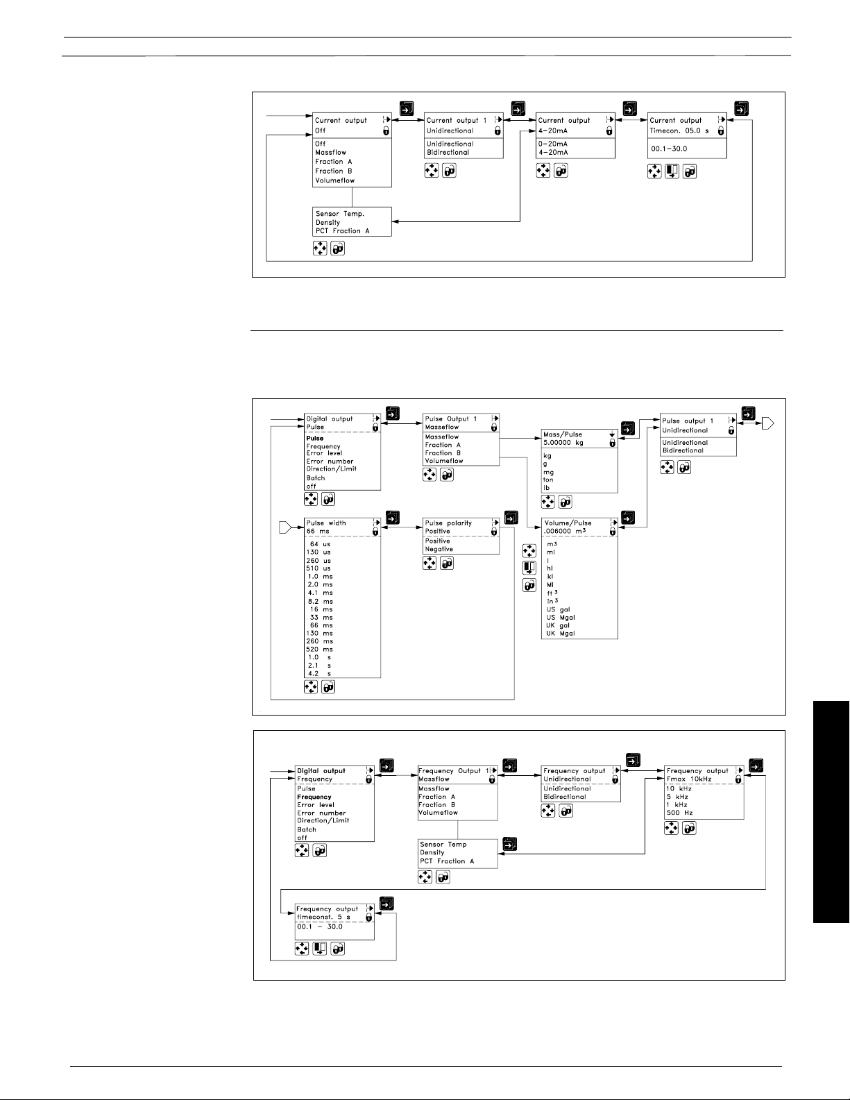
Current output
Fluid Components Intl
Menu detail
The current output should be set to off when not used, otherwise an error will be pending if the meter
detects an open loop.
Digital output
Pulse
Digital output
Frequency
The digital output menu can be used for generating a frequency proportional output signal, for
pulse signal (totalizing), indicating error level/number, limit or flow direction or as batch output. Only
one function can be implemented for each output section.
Document 06EN003327 Rev. -
57 FlexCOR
Commissioning
™ Model CMF Series
Page 8
Fluid Components Intl
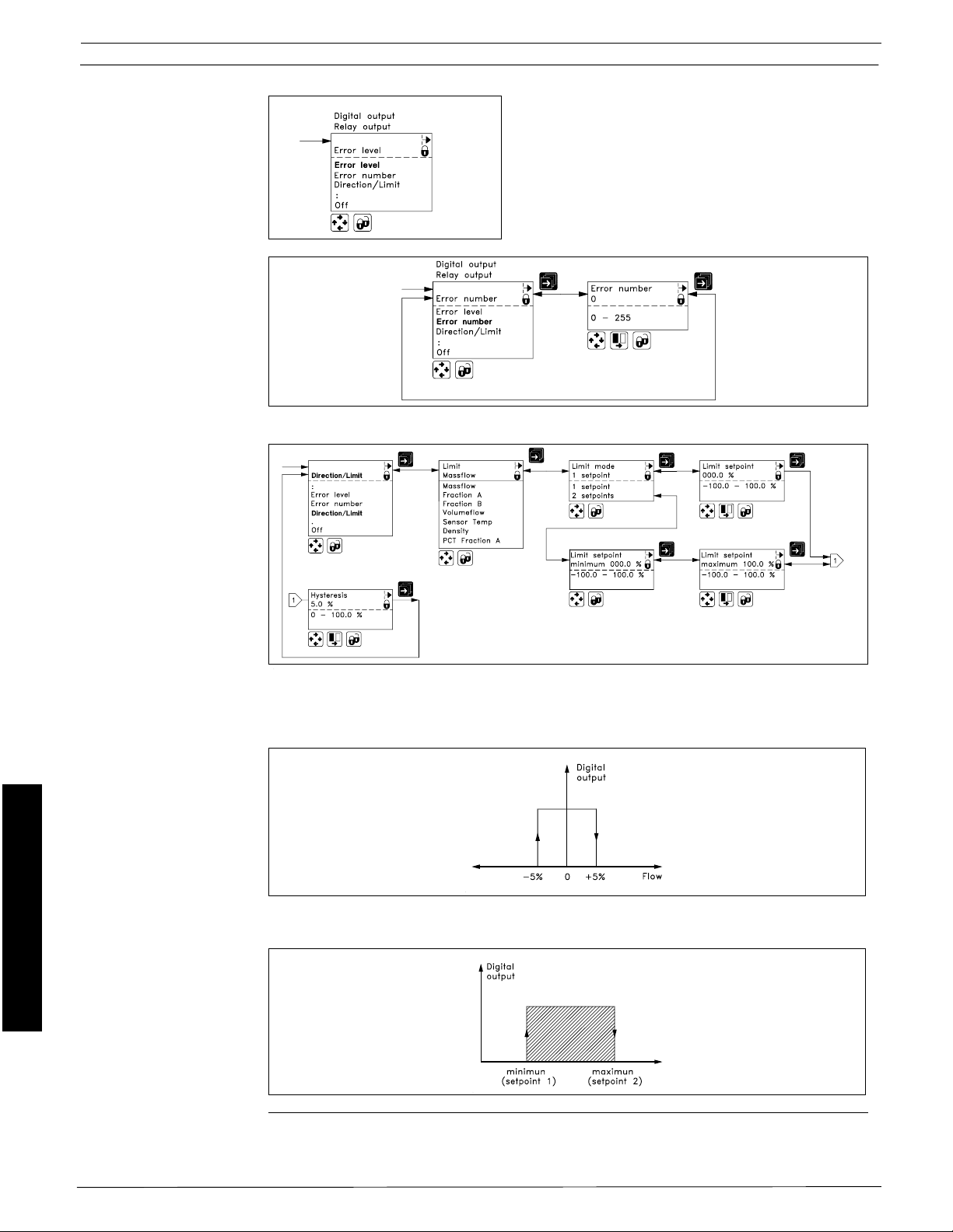
Digital output
Error level
Digital output
Error number
Digital output
Limit/direction
Menu detail
If the error statusis to be output at the digital output there
are two options. Select error level to output the system’s
current error status or error number if a specific error is
to be indicated by the digital output.
Both types of error message are described in more
detail in the section error system.
Acceptance level is set in the basic settings.
Digital output
Flow direction
1 set point
2 set points
Commissioning
2 separate set points
Limit switches are available for both digital and relay output and can be used for mass flow, fraction,
volume flow, temperature or density.
To set the output to show flow direction then select: 1 set point at 0% flow; hysteresis 5%.
To have a flow, temperature, density or fraction area monitored via the digital output then select
2 set points.
If 2 set points have to activate two separate outputs, each set point has to be selected individually
one for digital output and the other for relay output.
FlexCOR™Model CMF Series 58
Document 06EN003327 Rev. -
Page 9

Digital output
Batch menu
Fluid Components Intl
Menu detail
Batch
Menu description
Batch menu
Batching can be set to mass or volume. The desired quantity is called the batch quantity.
Batch compensation allows addition/subtraction of a fixed quantity in order to compensate for
valve delays, etc.
Compensation to be carried out dynamically, i.e. independently of the flow rate in the system, the
transmitter can calculate the system’s time constant – this is known as the lead const.
Batch time error is used to monitor that a batch is executed within the specified period, which is
set by max. batch time. If the batch is not completed within the time set an error message will output
by the Errorlog/pending.
Batch overrun error monitors that the quantity passing through the valve when it is closed does
not exceed the quantity set. This function can detect irregular valve function due to blockage, failure
to close due to wear, etc. The error is notified by the errorlog/pending function.
Batch counter is used to set the batch display. If up is selected the display counts from 0 up to
the selected batch quantity. If down is selected it counts down from batch quantity to 0 for each
batch. The operator can follow the progress when running in a batch application.
Commissioning
Document 06EN003327 Rev. -
59 FlexCOR
™ Model CMF Series
Page 10
Fluid Components Intl
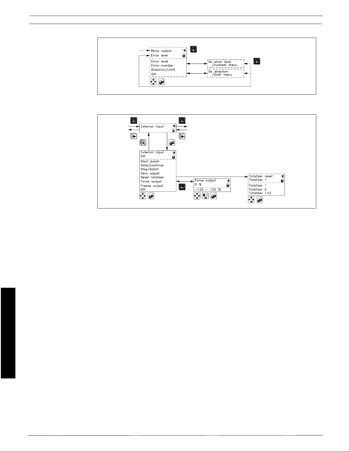
7.5.2 Relay output
7.5.3 External input
Menu detail
The output functions error level, error number and direction/limit can also be implemented on the
relay output. Programming of the realy output is identical as is the digital output.
Commissioning
External input menu
The transmitter has one digital input available. If the input is activated with a logic signal
(11 - 30 V d.c.) the meter carries out the activity selected under the menu option. The following
functions can be selected:
Start batch. If the transmitter is used for batching this can be activated automatically by this
function.
Hold/continue is also used in connection with batching and on being activated for the first time
will pause the batch. When activated again it will continue the batch.
Stop batch will stop the batch, i.e. the digital output goes to logic 0. The batch is then reset.
Zero adjust activates the automatic 0-point adjustment.
Reset totalizer can be used to reset internal totalizer 1, 2 or both.
Force output forces all outputs to adopt the value selected in the menu. For example, if 100% is
selected, this means that on activation of external output the current output will show 20 mA and
the frequency output will show 10,000 kHz if set to 0 - 10 kHz.
Freeze input freezes all the current measured values in the display and outputs.
FlexCOR™Model CMF Series 60
Document 06EN003327 Rev. -
Page 11

7.5.4 Sensor
characteristics
Fluid Components Intl
Menu detail
Correction factors
When the SENSORPROM® memory unit is installed only the parameters correction factor,
density offset, fraction offset and table slope can be changed.
If you wish to change the mass flow measurement a percentage shift can be set under the menu
option correction factor. The change affects all flow-related values.
If you wish to change the density measurement a percentage shift can be set under the menu option
density factor.
If an offset needs to be added to the density measurement this is done with density offset.
If the fraction flowmeter function is used it is possible to customize the function in accordance with
the following equation:
Fraction = Ax + B, where
A = Table slope
B = Fraction offset
x = Measured fraction
Commissioning
Document 06EN003327 Rev. -
61 FlexCor
™ Model CMF Series
Page 12
Fluid Components Intl
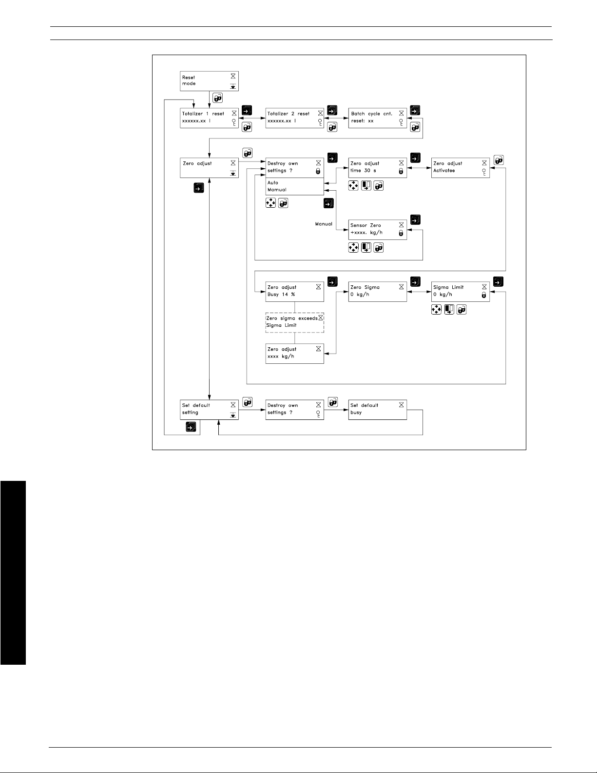
7.5.5 Reset mode
Menu detail
Reset mode
Menu description
Commissioning
Reset mode
In the reset mode menu the totalizer 1 and 2 and the batch cycle counter can be reset.
0-point adjustment
0-point adjustment of the flow meter is done in the zero adjust menu. The adjustment can be made
automatically where the meter measures and calculates the correct 0-point. In manual mode the
0-point can be programmed if this is known. Normally the automode is used.
Zero adjust time determines the period of time for the automatic 0-point adjustment. As default
a period of 30 sec. is used which normally is enough for a stable 0-point mesurement. If the
flowmeter is used where small flow rates are measured very accurately, a longer integration time
can be selected, to obtain better 0-point measurement.
Setting the 0-point is carried out by activating zero adjust. A number of individual 0-point
measurements are made. The 0-point found is shown as zero adjust. The value zero sigma
shows the standard deviation of the individual measurements made. The standard deviation (zero
sigma) must be within a window, which is pre-defined by Fluid Components Intl. This window is
called sigma limit. If the standard deviation is outside the window the following message is shown
in the display: “Zero sigma exceeds sigma limit”. In this case check the installation, ensure that
the pipe is full and that there is absolute 0-flow present. Then repeat the 0-point adjustment. The
new 0-point is automatically stored in the SENSORPROM
®
and will remain at power down
situations.
FlexCor™ Model CMF Series 62
Document 06EN003327 Rev. -
Page 13
Example; setting the
0-point
Fluid Components Intl
Keypad operation Implementation Display
Push for 3 sec. To access the Password
user password 0000
Push once To unlock password CHANGE
0000
Push once To enter 1000 as CHANGE
password 1000
Push once To lock password and to CONV.SETUP MODE>
enter the menu Basic settings
Push 4 times To go to reset Reset
mode menu mode
Push once To enter the reset Totalizer 1 reset
mode menu xxx. G
Push twice To go to zero Zero adjust
adjust menu
Push once To enter the zero Zero adjust
adjust menu Auto
Push twice To go to zero Zero adjust
adjust activation +xxxxxx kg/h
Push once To activate the 0-point Zero adjust
adjustment routine +xxxxxx kg/h
Transmitter preforms Counting up from 0
0-point adjustment to 100%
New 0-point is calculated Zero adjust
and stored in SENSORPROM
Push twice/ Transmitter reverts to
hold 3 sec. standard operation
â
+yyyyyy kg/h
Menu detail
Document 06EN003327 Rev. -
63 FlexCor
Commissioning
™ Model CMF Series
Page 14

Fluid Components Intl
7.5.6 Service mode
Menu detail
Commissioning
All previous settings are re-initialized when service mode is exited using the top up key.
The error system
The error system is divided into an error pending list and a status log list. Time is gained as days,
min. and hours since the error has occurred.
The first 9 pending errors are stored in error pending. When an error is removed it is removed from
error pending.
The last 9 errors are stored in the error log. When an error is removed it is still kept in error log. Errors
in error log is kept in 180 days.
Error pending and error log are accessible when enabled in the operator menu.
FlexCOR™Model CMF Series 64
Document 06EN003327 Rev. -
Page 15

Fluid Components Intl
Service mode
Menu description
Service mode
The service mode menu can be used to check the flowmeters operation or as diagnostic tools
for trouble shooting.
Flow rate indicates the actual flow rate in %, while tests are being conducted in SERVICE MODE.
Low flow cut-off can be used to supress fluctuating flow transients while experimenting.
Current output can be used to simulate a given flow, temperature, density signal etc. The feature
can be used to check/calibrate connected equipment. Under current output forced a value
between 0 and 24 mA can be set.
If 3 current outputs are used the function can also be used for identification of the individual outputs
by activating these in turn.
Digital output can also be simulated. If the output is selected as limit functions or batch a high or
low state can be simulated. If the digital output is used as flow, density or temperature output, a
signal of 1 to 12,500 Hz can be simulated.
Relay output is used to simulate the relay as on or off.
Special information is used for making diagnosis of the sensor function under the present
operating conditions. This makes it possible to reveal errors caused by errors in the sensor itself
or errors due to application conditions disturbing the sensor function.
Driver signal indicates the current which is necessary to drive the sensor. The driver current is
dependant of sensor size. In the table below the typical values for normal operation conditions are
displayed. The driver current will increase if there is damping in the application, such as air/gas
bubbles, hydraulic generated noise such as flow pulsations or dampning created by mechanical
noise such as vibrations. The driver output circuit can deliver 36 mA maximum.
Size Driver frq. [Hz] Driver current [mA]
CMF - A 120 12
CMF - B 110 7
CMF - C 135 15
CMF - D 165 15
CMF - E 125 10
CMF - F 125 12
Pick-up 1/2 amplitude indicates the signal level at the two pick-up’s. In normal operation
conditions the level should be greater than 50 mV. A lower value indicates damping in the system
and can be due to air/gas bubbles in the sensor.
The signal on pick-up 1 and 2 should be within the same value ±20 mV. A bigger difference
indicates noise in the system due to hydraulic or mechanical errous conditions.
Sensor frequency gives the resonant frequency of the sensor in Hz. The frequency is dependent
on dimension as well as the density of the liquid measured, see table below. Values more than
±20 Hz away of the values in the table indicate problems, check cabling, connection and operation
conditions.
Sensor temperature gives the actual temperature of the sensor. The function can be used to see
whether possible errors occur because the sensor is exposed to an excessively high temperature.
Futhermore, errors due to missing/wrong connection of the temperature transmitter between
sensor and converter can be detected.
Sensor zero can be used to check whether the zero point of the meter is satisfactory.
Operating time indicates how many days the signal converter has been in operation.
Commissioning
Document 06EN003327 Rev. -
65 FlexCOR
™ Model CMF Series
Page 16

Fluid Components Intl
7.5.7 Operator menu
setup
Menu setup
The upper line is always active and can never be deselected.
Commissioning
The two lower lines are for individual operator information. The forward key is used by the operator
to scroll through information.
- A closed lock key in the operator menu setup, means that the menu is enabled when viewing
the operator menu.
- A open lock key symbol, means that the menu is not available in the operator menu.
The middle line can either be used as a heading “Text line” for the lower line, or as a value reading.
A flow reading can be individually selected for each menu.
The lower line may be used for an additional flow reading to the reading already available in the
upper line.
FlexCOR™Model CMF Series 66
Document 06EN003327 Rev. -
Page 17

7.5.8 Product identity
7.5.9 Change password
Fluid Components Intl
Menu setup
Software version of add-on module is only available if the add-on module has been installed.
7.5.10 Language mode
Commissioning
Document 06EN003327 Rev. -
67 FlexCOR
™ Model CMF Series
Page 18

Fluid Components Intl
7.5.11 HART
communication
(Add-on module)
®
Menu setup
Commissioning
FlexCOR™Model CMF Series 68
Document 06EN003327 Rev. -
Page 19
7.6.1 Operator menu
Flowrate
Fluid Components Intl
The 1st displayline will always be active and show the value enabled in the operator menu setup.
- Massflow rate, volumeflow rate, density, temperature, totalizer1, totalizer2
- Totalizer 2
nd
The 2
and 3th display lines are individually set in the operator menu. The page forward key steps
through the enabled settings.
- Mass flow rate
- Volume flow rate
- Density
- Temperature
- Totalizer
- Totalizer reset
- Batch control
- Batch cycle counter
- Batch cycle counter reset.
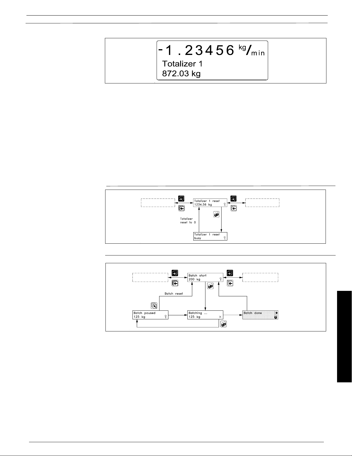
7.6.2 Totalizer
7.6.3 Batch
A totalizer is reset by pressing the lock key when the corresponding totalizer reset window is open.
A batch can be started, paused or stopped from the operator menu, in addition to the externally
operated batch control. The batch is controlled using the lock and the top up keys.
Commissioning
The lock key:
- Starts the batch
- Holds the batch (pause) when pressed during batching
- Continue the batch when pressed during a pause.
Batch cycle counter
Batch cycle counter reset
Document 06EN003327 Rev. -
The top up key resets a batch completely during a pause.
The accumulated number of performed batches can be viewed when enabled in the operator
menu setup.
The batch cycle counter is reset by pressing the lock key in the “batch cycle cnt reset” menu.
69 FlexCOR
™ Model CMF Series
Page 20

Fluid Components Intl
7.7.1 Parameters
Commissioning
Parameter Factory setting Settings available
Password
Password 1000 1000 – 9999
Basic settings
Flow direction Positive Positive, negative
Massflow max. Dim. dependent Dim. dependent
- Weight units Dim. dependent mg, g, kg, ton, lb
- Time units Dim. dependent s, min, h, d
Volumeflow max. Dim. dependent Dim. dependent
- Volume units Dim. dependent m3, ml, l, hl, kl, Ml, ft3, in3, US G, US MG,
UK G, UK MG
- Time units Dim. dependent s, min, h, d
Density
- Minimum +0.1 g/cm
- Maximum +2.0 g/cm
3
3
-20000.0 kg/m3 - +20000.0 kg/m
-20000.0 kg/m3 - +20000.0 kg/m
3
3
- Weight units g mg, g, kg, ton, lb
- Time units cm
3
cm3, m3, ft3, in
3
Sensor temp.
- Minimum -50 °C -250 °C - +250 °C
- Maximum +250 °C -250 °C - +250 °C
- Temperature units °C °C, °F, K
Fraction A/B max. Application dependent Application dependent
- Weight units kg mg, g, kg, ton, lb
- Time units h s, min, h, d
Totalizer 1 Mass flow Mass flow, fraction A, fraction B, volume flow
Forward Forward, reverse, net
Dim. dependent mg, g, kg, ton, lb
Totalizer 2 Volume flow Mass flow, fraction A, fraction B, volume flow
Forward Forward, reverse, net
Dim. dependent m3, ml, l, hl, kl, Ml, ft3, in3, US G, US MG,
UK G, UK MG
Low flow cut off 1.5 % 0 – 9.9 %
Empty pipe limit Dim. dependent -20000.0 g/cm3 - +20000.0 g/cm
3
Noise filter 3 1 (min.) to 5 (max.)
Error level Warning Fatal, permanent, warning
Output
Current output 1 O ff Mass flow, fraction A, fraction B, volume flow,
sensor temp., density, pct. fraction A, off
- Direction Unidirectional Unidirectional, bidirectional
- Output mode 4 – 20 mA 0 - 20 mA, 4 - 20 mA
- Time constant 5 s 0 – 30 s
Digital output 1 Pulse Pulse, frequency, error level, error number,
direction/limit, batch, off
Pulse Mass flow Mass flow, fraction A, fraction B, volume flow
- Amount/pulse Dim. dependent Dim. dependent
- Pulse polarity Positive Positive, negative
- Pulse width 66 ms 64 us, 130 us, 260us, 510 us, 1.0 ms, 2.0 ms,
4.1 ms, 8.2 ms, 16 ms, 33 ms, 66 ms, 130 ms,
260 ms, 520 ms, 1.0 s, 2.1 s, 4.2 s
Frequency Of f Mass flow, fraction A, fraction B,
volume flow, sensor temp., density, pct.
fraction A
- Direction Unidirectional Unidirectional, bidirectional
- Max. frequency 10 kHz 500 Hz, 1 kHz, 5 kHz, 10 kHz
- Time constant 5 s 0 – 30 s
Error number Off 0 - 255
FlexCOR™Model CMF Series 70
Document 06EN003327 Rev. -
Page 21

Fluid Components Intl
Direction/limit Of f Mass flow, fraction A, fraction B, volume flow,
sensor temp., density, pct. fraction A
- Limit mode 1 set point 1 set point, 2 set points
- Setpoint(s) 0 % (0/100 %) -100 – 100 %
- Hysteresis 5 % 0 – 100 %
Batch Mass, fraction A, fraction B, volume
- Quantity 5 kg , 5 l 0 – 9999999 kg, 0 – 9999999 l
- Compensation 0 kg , 0 lq -100000 – 100000 kg, -100000 – 100000 l
- Counter Down Up, down
Relay output 1 O ff Error level, error number, direction/limit, off
External input
External input Off Start batch, hold/continue (batch), stop batch,
zero adjust, totalizer reset, force output,
freeze output, off
Sensor characteristics
Correction factor 1 -99.999999 – 99.999999
Density offset 0 -9999.9999 – 9999.9999 kg/m
Density factor 1 -9.999999 – 9.999999
Fraction offset 0 -9999.9999 – 9999.9999 kg/h
Table slope 1 -9999.9999 – 9999.9999
3
Language English English, German, French, Danish, Swedish,
Finish, Spanish, Russian, Italian, Portugese
Operator menu
Primary field Mass flow Mass flow, volume flow, fraction A, pct. fraction
A, fraction B, totalizer 1, totalizer 2, sensor
temp., density
Title/subtitle line Mass flow Massf low, mass flow %, volume flow, volume
flow %, fraction A text, fraction A, fraction A %,
fraction B text, fraction B, fraction B %, pct.
fraction A, density, sensor temp, totalizer 1,
totalizer 2, batch cycle cnt.
7.7.2 Dimension-dependent factory setting
Sensor Mass flow Volume flow Pulse output & factory setting
type Factory Factory Mass Pulse Totalizer Volume Pulse Totalizer
setting Min. Max. setting Min. Max. pr. pulse unit pulse pr. pulse unit pulse
kg/h kg/h unit unit
CMF - A 20 125 20 125 1 g g 1 ml ml
CMF - B 75 - 500 75 - 500 1 g g 1 ml ml
CMF - C 300 - 2000 300 - 2000 10 g g 10 ml ml
CMF - D 1500 - 10000 1500 - 10000 1 kg kg 1 l l
CMF- E 7500 - 50000 7500 - 50000 1 kg kg 1 l l
CMF - F 25000 - 100000 25000 - 100000 10 kg kg 10 l l
Commissioning
Document 06EN003327 Rev. -
71 FlexCOR
™ Model CMF Series
Page 22

Fluid Components Intl
7.8.1 Error handling
Error system
The converter system is equipped with an error and status log system with 4 groups of information.
- Information without a functional error
- Warnings which may cause malfunction in the application. The cause of the error may
disappear on its own
- Permanent errors which may cause malfunction in the application.
- Fatal error which is essential for the operation of the flowmeter
2 menus are available in the service and operator menus for registration of information and errors
- Error pending
- Status log
Error pending
The first 9 standing errors are stored in “error pending”. When an error is removed it clears from
“error pending”.
The acceptance level for “error pending” can be individual configured to a particular application.
The acceptance level is set in the “basic setting” in the setup menu.
Acceptance levels
- Fatal error: Fatal errors are registered as errors
- Permanent errors (Permanent and fatal errors are registered as errors)
- Warning (Default value): Warnings, permanent and fatal errors are registered as errors
The error information is displayed in the title and subtitle line. The title line will show the time since
occurrence of error. The subtitle line will flash between an error text and a remedy text. The error
text will indicate type of error (I, W, P or F), error no. and the error text. The text will inform the operator
of the action to take to remove the error.
Commissioning
Status Log
Like “error pending” except that information, warnings, permanent and fatal errors are always
stored in the “status log”. The “status log” stores the last 9 message during the last 180 days.
Alarm field
The alarm field on the display will always flash with an error pending.
Error output
The digital and relay output can be individually activated by an error (error level). The relay output
is default selected to error level. An output can also be selected to activate on a single error number.
The alarm field, error output and error pending will always operate together.
The analog output will turn to a 1 mA level when in the 4-20 mA mode.
Operator menu
Error pending and status log are as default enabled in the operator menu.
FlexCOR™Model CMF Series 72
Document 06EN003327 Rev. -
Page 23

Fluid Components Intl
7.8.2 List of error
numbers
Error Error text #Comment Outputs Input
No. Remedy text status status
1 I1 - Power on
OK Power on has activated Active Active
2 I2 - Add-on Module
Applied A new module has been added to the system Active Active
3 I3 - Add-on Module An add-on module is defective or has been removed.
Install This can also be an internal add-on module Active Active
4 I4 - Param. corrected A less vital parameter in the converter has been
OK replaced by its default value Active Active
20 W20 - Totalizer 1 During initialization the check of the saved totalizer
Reset manually value has failed. It is not possible to rely on the
20 W20 - Totalizer 2 During initialization the check of the saved totalizer
Reset manually value has failed. It is not possible to rely on the
21 W21 - Pulse overflow Actual flow is too big compared with pulse width and Reduced
Adjust pulse settings mass/pulse pulse width Active
22 W22 - Batch timeout Duration of batching has exceeded a predefined Batch out-
Check installation max. time put on zero Active
23 W23 - Batch overrun Batch quantity has exceeded a predefined maximum Batch out-
Check installation overrun mass or volume put on zero Active
24 W24 - Batch neg. flow
Check flow direction Negative flow direction during batch Active Active
30 W30 - Flowsaturated
Adjust max. flow Flow is above Q
31 W31- Empty pipe Pipe is empty Zero Active
32 W32 - Temp. to high The temperature of the fluid has exceeded the max.
Adjust temperature temperature rating of the sensor (180 °C) Active Active
33 W33 - Temp. to low The temperature of the fluid has exceeded the min.
Adjust temperature temperature rating of the sensor (-50 °C) Active Active
34 W34 - Zero Adj. fail The zero-point adjustment values are outside the limit
Check flow = zero because there is not zero flow in the sensor. Check
35 W35 - Current Out 1 Current output exceeds 120%. Ensure that the sensor is
Check max. settings correctly sized and check max. flow setting Active Active
36 W36 - Freq/Pulse Out1 Freq/Pulse output exceeds 120%. Ensure that the sensor
Check max. settings is correctly sized and check max. flow setting Active Active
40 P40 - SENSORPROM
Insert SENSORPROM® unit not installed Active Active
41 P41 - Parameter range A parameter is out of range.
Switch off and on The error will disappear at the next power-on Active Active
42 P42 - Current output Current loop is disconnected or the loop resistance
Check cables is too big Active Active
43 P43 - Internal error Internal error
Switch off and on Active Active
49 P49 - Protec. viol. Too many errors occured at the same time.
Switch off and on Some errors are not detected correctly Active Active
50 P50 - Temp. cable Error in temperature sensor, check cables and
Check cable connectors Active Active
51 P51 - Pick-up 1 Pick-up 1 amplitude too low. Check cables or application
Check cable/install. for damping (air/gas in liquid) Active Active
52 P52 - Pick-up 2 Pick-up 2 amplitude too low. Check cables or application
Check cable/install. for damping (air/gas in liquid) Active Active
60 F60 - CAN comm. error CAN bus communication error. An add-on module, the
Converter/add-on module display module or the converter is defective Zero Inactive
61 F61 - SENSORPROM
Replace unit Active Active
62 F62 - SENSORPROM
Replace product ID. The SENSORPROM
63 F63 - SENSORPROM
Replace unit Active Active
70 F70 - Pick-up phase Check cables/polarity Active Active
71 F71 - Driver phase Check cables/polarity Active Active
80-83 F80, 81, 82, 83 - Internal error Restart or replace Active Active
84 F84 - Sensor level Pick-up amplitud saturated Active Active
97 F97 - Add-on module to old Replace Active Active
®
®
®
®
saved totalizer value. The totalizer value must be
reset manually in order to rely on future readings Active Active
saved totalizer. The totalizer value must be reset
manually in order to rely on future readings Active Active
settings Max. 120 % Active
max.
zeroflow conditions, valves, pumps etc. Active Active
err. It is not possible to rely on the data in SENSORPROM
ID The SENSORPROM® unit ID do not comply with the
type of product. Zero Inactive
It is not possible to read from the SENSORPROM
®
unit is from another
®
®
Commissioning
Document 06EN003327 Rev. -
Error code level:
W = Warning, F = Fatal, P = Permanent
73 FlexCOR
™ Model CMF Series
Page 24

Fluid Components Intl
8. Trouble shooting
8.1 Transmitter
Symptom Output Error Cause Remedy
signals code
Empty display Minimum 1. Supply voltage 1. Check supply voltage
2. Transmitter defective 2. Replace Transmitter
No flow signal Minimum 1. Current output deselected 1. Activate current output
2. Digital output deselected 2. Activate digital output
3. Reverse flow direction 3. Change direction
W31 Measuring pipe empty Ensure that the measuring
pipe is full
F60 Internal error Replace Transmitter
Undefined P42 1. No load on current output 1. Check cables/connections
2. Transmitter defective 2. Replace Transmitter
P41 Initializing error Switch off Transmitter, wait
5 seconds and switch on again
Indicates flow Undefined Measuring pipe empty Select empty pipe limit
with no flow Ensure that the measuring
in pipe pipe is full of liquid
Unstable Unstable 1. Pulsating flow 1. Increase time constant
flow signal
2. Air bubbles in medium 2. Ensure medium does not
contain air bubbles
3. Vibrations 3. Ensure that the sensor is
mounted on a rigid frame
without vibrations
4. Pump noise 4. Ensure that pump
frequency is different from
resonance frequency of
sensor
Measuring error Undefined Faulty zero-point Make new zero-point
adjustment
Loss of totalizer OK W20 Initializing error Reset totalizer manually
T. s.
data
FlexCOR™ Model CMF Series 74
P40 No SENSORPROM® unit Install SENSORPROM® unit
F61 Deficient SENSORPROM
unit
F62 Wrong SENSORPROM
unit
F63 Defective SENSORPROM
unit
F80-83 Loss of internal data Replace Instrument
Maximum W30 Flow exceeds 120% of Q
W21 Pulse overflow
· Mass/pulse too small Change mass/pulse
· Pulse width too large Change pulse width
®
Replace SENSORPROM® unit
®
Replace SENSORPROM® unit
®
Replace SENSORPROM® unit
max.
Check Q
(Basic Settings)
max.
Document 06EN003327 Rev. -
Page 25

Fluid Components Intl
8.2 Check for air in the
system
In case of large air collections non-homogenesously distributed in the sensor, the air in the liquid
can disturb the flowmeter and lead to incorrect measurement, whereas homogenesously
distributed air and solids will not disturb measurement.
1) 0-point unstable or exceeding limit (SIGMA LIMIT, refer to reset menu)
2) Measurement of mass flow rate incorrect ?
3) Output signal unstable
4) Error symbol on (type W31, W34, F70, F71)
If one or more of the above symptoms is observed, the cause can be that there is air in the liquid.
Air in the system can be checked through the following tests:
1. Use of Service Mode
Go to the service mode menu and read the values under the menu driver amplitude. Compare
the values with the table listed in section 7.5. If the current is higher than specified it might be
because there are air bubbles in the liquid.
2. Increase of pump pressure
Close the valve, if any, after the sensor. Start the pump and consequently increase the pump
pressure. If the 0-point becomes more stable there are non-homogenseously distributed air
bubbles in the system.
3. Connection of pick-up signals in parallel (only possible for 19“ versions)
The fault can also be found by connecting pick-up 1 and pick-up 2 in parallel. Move the leads on
terminal 85 to terminal 87 on the connection PCB. This will send the same pick-up signal into both
channels in the converter.
If the 0-point becomes more stable by one of the above mentioned examples the conclusion is
that there is air in the system which affects the flowmeter operation.
8.3 Check of 0-point
accuracy
Air generation souces
The air can typically be generated by the following causes:
1) Suction pressure of pump too low (pump cavitates)
2) Blocked filter or other obstruction ahead of sensor. This can produce cavitation and air
formation
3) Volatile liquid producing air bubbles at low pressure
4) Pressure in sensor too low because too low a pressure in the piping after the sensor
5) Incorrect location of sensor, refer to Chapter 4 "Installation of sensor".
Check whether the 0-point is within the accuracy specifications given by Fluid Components Intl.
Check as follows:
Go to the basic settings menu, set low flow cut-off to 0%. Go to totalizer 1, select bidirectional mode
and select massflow.
Go back to operator menu, reset the totalizer 1 (if selected in the operator menu, otherwise reset
the totalizer in the reset menu).
Go to totalizer 1 in the operator menu and monitor the value. The totalizer now displays the actual
0-point of the system. Read the totalizer value after 1 min. mutiply the value with 60, this will give
the value xxxx.x kg/h. This can for the sensor dimension in question be compared with the
specifications given under Section 2.3 “Meter uncertainty”, max. zero point error.
Document 06EN003327 Rev. - 75 FlexCOR™ Model CMF Series
T. s.
 Loading...