

Page 1

Fluid Components Intl
4. Installation of
sensor
4.1 Location
4.2 Cavitation
Installation of sensor
To ensure the optimum function of measuring equipment it is important that the installation
instructions are followed closely, point by point.
The flowmeter can be located both indoors and outdoors, but the following conditions must be
observed:
Liquid temperature: -58 to 356°F (-50 to +180°C).
The grade of enclosure can be choosen from
IP 20 up to IP 67.
When the temperature difference between a
liquid and the surroundings is large, the sensor must be insulated to prevent 2-phase flow
and thereby measuring inaccuracy. This applies especially in the case of low flow.
Important!
The sensor must always be completely filled with a homogeneous liquid or gas in single
phase, otherwise measuring errors will occur.
Avoid cavitation in the system, i.e. sucking in or
releasing air into the system, because this may
produce errors.
Static back pressure minimum 0.1 - 0.2 bar.
4.3 Air bubbles
4.4 Mounting
Avoid large quantities of air collecting in the
sensor because these will disturb measurement. Homogeneous mixtures of air and solids, however, will not disturb measurement.
When there is air in the liquid, installation of an
air trap ahead of the meter is recommended.
If there is air/gas in the liquid or liquids which
are volatile, horizontal sensor mounting is
recommended.
The unit must be mounted on a flat wall or steel
frame (vibration-free).
FlexCOR™ Model CMF Series 22
Document 06EN003327 Rev. -
Page 2

4.5 Vibrations
4.6 Cross-talk
Fluid Components Intl
Locate the flowmeter as far away as possible from components that generate mechanical vibration
in the piping.
Or ensure that there is no direct connection with
them e.g. by using flexible connections.
The flowmeter can also be located after a bend.
Installation of sensor
4.7 Magnetic fields
4.8 Transportation/
storage
Document 06EN003327 Rev. -
If the flowmeters are located close to each other, e.g. in the same pipe section, the meters may
disturb each other in measurement, especially with low flow. Locate the meters with a flexible
connection instead of a permanent connection.
Avoid mounting the meter on the same steel frame. i.e. insulate the meters mechanically.
Locate the sensor a minimum of 10 inches (25 cm) from strong magnetic fields (motors,
transformers, electrically operated valves, etc.).
The sensor is a fragile piece of equipment and shall be placed in its storage carton when
transported or stored. If this is not possible, the sensor must be packed so the packing enclosure
can withstand the hazards from transportation or storage.
23 FlexCOR™ Model CMF Series
Page 3

Fluid Components Intl
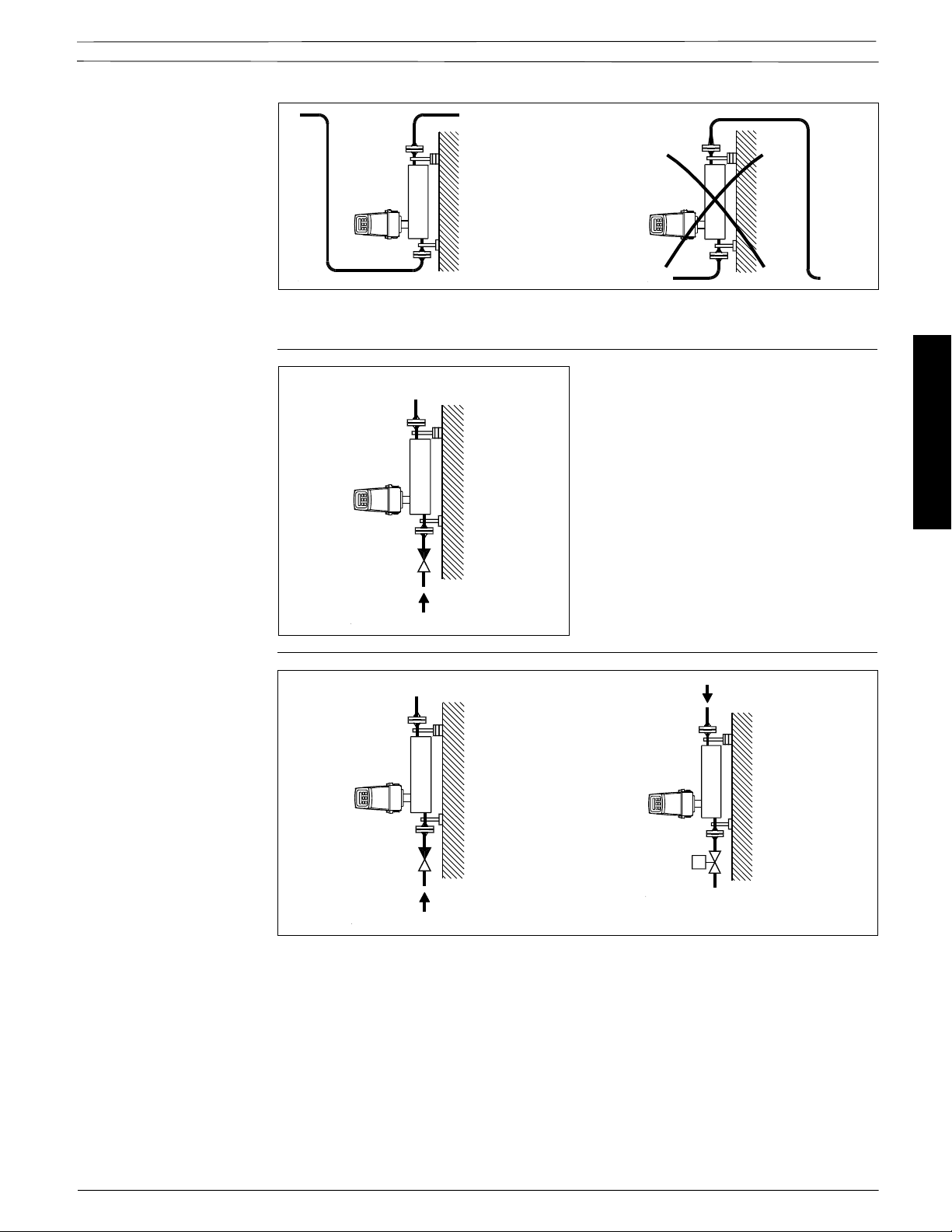
4.9 Horizontal mounting
in pipe CMF B-F
Locate the sensor low in the pipe system in order to avoid low pressure in the sensor and
consequent air separation in the liquid.
If the flowmeter is mounted horizontally it is self-emptying.
With low flow, horizontal mounting is recommended, any air bubbles are easier to remove.
Flow direction
Installation of sensor
0-point adjustment
Static back pressure
Valve
Forward
Normal
Valve
Reverse
Inverse
The arrow on the sensor indicates the direction of flow defined as “positive” (the meter is able to
measure flow in both directions).
If possible, the liquid should flow in the forward direction to avoid partial emptying of the sensor,
especially with low flow.
In addition there should be a valve (check/solenoid) that closes when the flow is zero so that the
liquid does not flow back and causes partial emptying of the sensor.
To facilitate 0-point adjustment, a valve with a good shut-off should always be mounted near the
sensor.
- The sensor should be completely filled with liquid.
- The valve must be closed.
- Wait a few minutes to let the flow stabilize at zero.
- Activate the 0-point adjustment, see Chapter 7 "Setting the 0-point".
FlexCOR™ Model CMF Series 24
Document 06EN003327 Rev. -
Page 4
4.10 Vertical mounting in
pipe
Fluid Components Intl
Locate the unit low in the pipe system in order to avoid under pressure in the sensor and
consequent air separation in the liquid.
Flow direction If possible, the liquid should flow up-wards to
Static back pressure
make bubble removal easier.
With vertical mounting, a check valve, which
closes on zero flow, must always be installed
so that the liquid cannot flow back and partially
empty the sensor.
The arrow on the sensor indicates positive
(forward) flow direction.
Valve
Direction of flow
0-point adjustment
Direction of flow
Installation of sensor
Document 06EN003327 Rev. -
Valve
Direction of flow
Valve
To facilitate 0-point adjustment, a valve with a good shut-off should always be mounted in line with
the sensor.
- The sensor should be completely filled with liquid.
- The valve must be closed.
- Wait a few minutes to let the flow stabilize at zero.
- Activate the 0-point adjustment, see Chapter 7 "Setting the 0-point".
25 FlexCOR™ Model CMF Series
Page 5
Fluid Components Intl
4.11 CMF - A
4.12 Location
Installation of sensor
To ensure the optimum function of the measuring equipment it is important that the
installation instructions are followed closely.
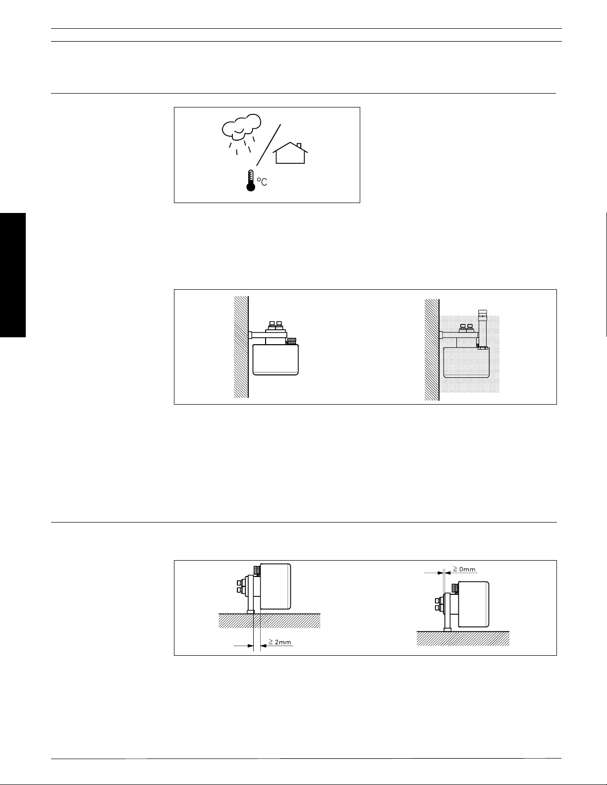
The flowmeter can be located both indoors and
outdoors, but the following conditions must be
observed:
Liquid temperature
The CMF - A is available in 2 versions.
Standard version: -40 to 257 °F (-40 to +125°C).
High temperature version: -40 to 356°F (-40 to +180°C).
For the high temperature version the multiple plug is raised from the sensor housing by a pipe.
It is possible to insulate the sensor and still having access to the plug.
4.13 Mounting
Important
When the temperature difference between a liquid and the surroundings is large, the sensor must
be insulated to prevent 2-phase flow and the loss of measuring accuracy. This applies especially
in the case of low flow.
The sensor must always be completely filled with a homogeneous liquid or gas in single phase,
otherwise measuring errors will occur.
If there is air/gas in the liquid or liquids which are volatile, horizontal sensor mounting is
recommended.
The mounting bracket supplied with the unit must always be used. The bracket must be mounted
on a wall or steel frame which is vibration free and mechanically stable.
FlexCOR™ Model CMF Series 26
Document 06EN003327 Rev. -
Page 6

4.14 Horizontal mounting
in pipe
Multiple plug orientation
Fluid Components Intl
Locate the sensor low in the pipe system in order to avoid low pressure in the sensor and
consequent air separation in the liquid. Due to the capillary tube effect, the sensor is not self
emptying.
When there is low flow, horizontal mounting is recommended, the air bubbles are easier to
remove.
To avoid separation of air from the liquid, a back pressure of min. 0.1 - 0.2 bar is recommended.
Installation of sensor
Flow direction
0-point adjustment
To obtain the optimum performance, the multiple plug should be mounted as shown in the drawing.
The multiple plug can be turned withing the angles stated.
The arrow on the sensor indicates the direction of flow defined as "positive" (the meter is able to
measure flow in both directions).
If possible, the liquid should flow in the direction of the arrow (on the sensor) to avoid partial
emptying of the sensor, especially with low flow.
In addition there should be a valve (check/solenoid) that closes when the flow is zero so the liquid
does not flow back to produce partial emptying of the sensor.
To facililate a good 0-point adjustment a valve should always be installed to ensure that 0-flow
condition can be obtained.
- The sensor should be completely filled with liquid.
- The valve must be closed.
- Wait a few minutes to let the flow stabilize at zero.
- Activate the 0-point adjustment, see Chapter 7 "Setting the 0-point".
Document 06EN003327 Rev. -
27 FlexCOR™ Model CMF Series
Page 7

Fluid Components Intl
4.15 Vertifical mounting
in pipe
Multiple plug orientation
Installation of sensor
Locate the unit low in the pipe system in order to avoid low pressure in the sensor and consequent
air separaton in the liquid.
Multiple plug
Flow direction
When mounting vertically, the orientation of the terminal box is not important, rotation, however, is
not allowed to exceed the stated angles of the sensor.
Forward
Reverse
The arrow on the sensor indicates the direction of flow defined as "positive" (the meter is able to
measure flow in both directions).
FlexCOR™ Model CMF Series 28
Document 06EN003327 Rev. -
Page 8

Fluid Components Intl
4.16 Before commission-
ing
Warning
4.17 Mounting of
pressure release
valve
Before installing the sensor read the maximum operating pressure (PN) on the sensor label. The
operating pressure indicates the pressure to which the measuring pipe and connections have
been designed for. The sensor has passed pressure tests of this value or greater. This, is not
the case with the sensor enclosure (i.e. the enclosure covering the measuring pipe). If for some
reason the measuring pipe fractures, a pressure will be generated in the enclosure.
The burst pressure for the CMF - B through F enclosure is approximately 725 psi (50 bar) and
approximately 1000 psi (70 bar) forCMF - A.
The pressure values are only approximate and therefore cannot be taken as an absolute value
indicating when a possible fracture or leakage will occur.
When working with operating pressures/media which may cause pipe fractures and possible
injuries to people, equipment or anything else, special precautions are recommended to be taken
when building-in the sensor i.e. special placement, shielding, pressure release valve or similar.
The sensor enclosure is supplied with a 1/8" nipple. When the nipple is removed a pressure
release valve can be connected to automatically shut off the flow to the sensor in case of leakage.
For instructions on the mounting, please refer to the section "Mounting of pressure release valve".
Important
Before removing the nipple from the sensor enclosure, note the following:
Penetration of humidity, liquid or particles into the sensor must be avoided as it may influence the
measurement and in worst case affect the measuring function. This, can be avoided when
following the procedure below:
1. Place the sensor in a dry, clean place leaving it to settle until it reaches ambient temperature,
approximately 68° F (20 °C).
2. Be careful when disconnecting the nipple and mounting the pressure release valve.
3. Check that the pressure release valve has been correctly mounted and thoroughly tightened
so that the sealing ring fits tightly. Always replace old sealing rings with new ones after each
removal.
Installation of sensor
Document 06EN003327 Rev. -
29 FlexCOR™ Model CMF Series
Page 9

Fluid Components Intl
4.18 Ex installations
Installation of sensor
Transmitters
The instrument can be used in a 19" rack version where the sensor can be installed in the ex-area.
The transmitter must be installed in a safe area or as compact (integral) Ex-d version for installation
in the ex-area.
For mounting in Ex areas
Approval EEx [ia] llC T4...T6. DEMKO No. 95D.117700X
19” Ex for mounting in safe areas
Approval EEx [ia/ib] m llB T4...T6. DEMKO No. 99E.125729X.
Ex-d system
Approval Ex de [ia] llC T4...T6. DEMKO No. 99E.124212X.
Marking
The marking has the following meaning according to European Norm EN 50014.
E: Certified to CENELEC standard.
Ex: Designates explosion proof material and indicates that the apparatus has been
approved in accordance with a certificate issued.
i: “Intrinsic safety” is a protection ensuring that the energy in the electric circuit is too small to ignite
the explosive atmosphere. There are two categories of intrinsic safety: “ia” and “ib”.
ia: In intrinsic safety category “ia”, the circuit must remain safe, even in the event of two
simultaneous errors occurring that are independent of one another.
ib: In intrinsic safety category “ib” the circuit must remain safe if one error occurs.
d: The enclosure of the of the signal converter is so strong that it can resist an explosion in-
side the enclosure. The enclosure is dimensioned in a way so that an explosion will not
effect the surroundings.
e: “Increased safety” is a constructional safeguard which ensures the apparatus does not
contain normally arcing or sparking devices, or hot surfaces that will cause ignition.
ll: Designates that the apparatus may be used in all areas (except mining).
B: Indicates the gas group in which the unit may be used.
T4...T6 The temperature class describes the maximum temperature which any exposed surface
of the equipment may reach. The sensor can have temperature class T3, T4, T5 or T6
depending on the temperature of the media. Please see technical data for the sensor.
T3: Max. surface temperature 392°F (200 °C) => (Max. media temperature 356°F (180 °C))
T4: Max. surface temperature 275°F (135 °C) => (Max. media temperature 248°F (120 °C))
T5: Max. surface temperature 212°F (100 °C) => (Max. media temperature 194°F (90 °C))
T6: Max. surface temperature 185°F (85 °C) => (Max. media temperature 167°F (75 °C))
FlexCOR™ Model CMF Series 30
Document 06EN003327 Rev. -
 Loading...