

Page 1
CHAPTER 2 - INSTALLATION FLUID COMPONENTS INTL
2. Installation
Receiving/Inspection
• Unpack carefully.
• Verify that all items in the packing list are received and are correct.
• Inspect all instruments for damage or contaminants prior to installation.
If the above three items are satisfactory, proceed with the installation. If not, then stop and contact a customer
service representative.
Packing/Shipping/Returns
These issues are addressed in Appendix C - Customer Service
Required Materials
Appropriate wire, cable, conduit, and a mating interface on the vessel.
Note:
Potting Y's for all the interconnecting wires are recommended when installing the instrument. Other
requirements may vary based on local wiring codes. An appropriate mating surface on the vessel is
also required.
Pre-Installation Procedure
Warning:
Caution:
Only qualified personnel should install this instrument. Install and follow safety procedures in
accordance with the current National Electrical Code. Ensure that power is off during
installation. Any instances where power is applied to the instrument will be noted in this manual.
Where the instructions call for the use of electrical current, the operator assumes all responsibility
for conformance to safety standards and practices.
The control circuit contains electrostatic discharge (ESD) sensitive devices. Use standard ESD
precautions when handling the control circuit. See below for ESD details.
The instrument is not designed for weld-in-place applications. Never weld to process connection
or a structural support.
Damage resulting from moisture penetration of the local enclosure is not covered by product
warranty.
Use Standard ESD Precautions
Use standard ESD precautions when opening an instrument enclosure or handling the level transmitter. FCI
recommends the use of the following precautions: Use a wrist band or heel strap with a 1 megohm resistor connected
to ground. If the instrument is in a shop setting there should be static conductive mats on the work table and floor
with a 1 megohm resistor connected to ground. Connect the instrument to ground. Apply antistatic agents to hand
tools to be used on the instrument. Keep high static producing items away from the instrument such as non-ESD
approved plastic, tape and packing foam.
Doc. No. 06EN003264 Rev. A 2 - 1 Models 12-64/8-66 Basic Switch
Page 2
FLUID COMPONENTS INTL CHAPTER 2 - INSTALLATION
The above precautions are minimum requirements to be used. The complete use of ESD precautions can be found in
the U.S. Department of Defense Handbook 263.
Verify Installation Location
Prepare the vessel for installation, or inspect the already prepared location to ensure that the instrument will fit into
the system. Prepare the necessary sealants or gaskets to provide a leakproof installation for the application if
required. The location of the 12-64 that should have been prepared at the time of order should be at least 20 pipe
diameters downstream and 10 pipe diameters upstream from any bends or interference in the process pipe or duct to
achieve the greatest accuracy.
Sensing Element Installation
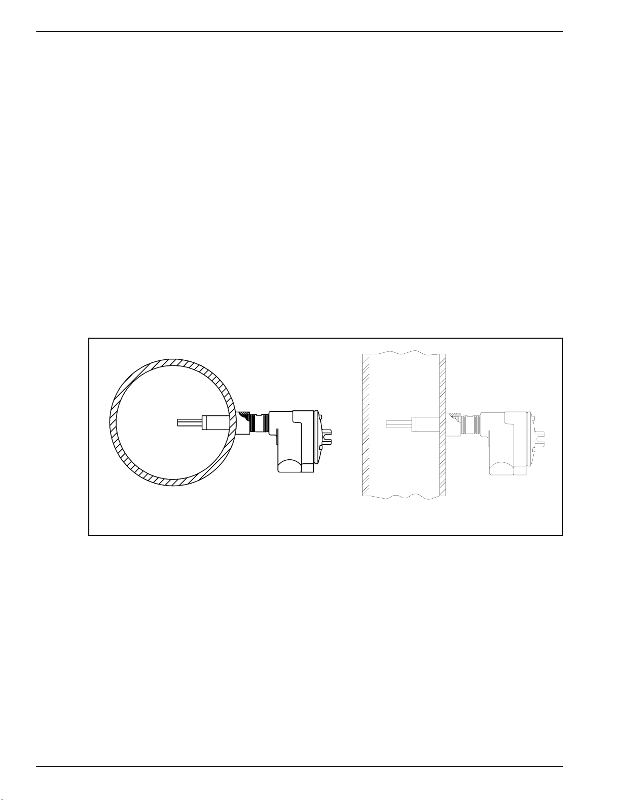
Install the sensing element in the process piping at the desired location. Verify that the flat area machined into the
sensing element is flat and level. If the flat is present it is machined on the sensing element near where it is screwed
into the enclosure. "FLAT UP & LEVEL" is also etched on the flat surface.
Apply a lubricant/sealant compatible with the process to all threads. Use a pipe wrench for 1-1/4 inch (32 mm) NPT
and larger connections, or an open-end wrench for 1-1/4 inch (32mm) NPT and smaller connections. All
connections should be tightened firmly. To avoid leaks, do not overtighten or cross-thread connections. The figures
in Appendix A and Figure 2-1, show this configuration.
If the sensing element is mounted in a downward direction, moisture build up in the enclosure needs to be avoided.
FCI recommends that an O-ring be used on the enclosure cover. In addition, attached conduits must be isolated by
using a conduit potting Y.
12-64 BASIC 8-66 BASIC
C00166-1C00033-1
Figure 2-1. Sensing Element Threaded Mounting
Control Circuit Installation
The configuration of the instrument is with the control circuit already installed in the local enclosure (the control
circuit is physically mounted with the sensing element).
Wiring Installation
Conduit Routing
All socket and/or terminal block connections are to be made through the 1 inch female NPT openings in the
enclosure. FCI strongly recommends that all electrical cables be run through an appropriate conduit for the
protection of the instrument and personnel.
Protection of the control circuit from moisture is an important consideration. Keep the entry of the conduit into the
Models 12-64/8-66 Basic Switch 2 - 2 Doc. No. 06EN003264 Rev. A
Page 3

CHAPTER 2 - INSTALLATION FLUID COMPONENTS INTL
enclosures in the downward direction so condensed moisture that collects in the conduit will not drain into the
enclosure. The local enclosure may be turned not more than 180° using the threads on the sensing element stand
pipe to gain an acceptable orientation. In addition, FCI recommends sealing off the conduit with a potting Y or other
sealing method to prevent moisture from entering the enclosure.
Minimum Wire Size
Table 2-1 shows the smallest gauge (maximum AWG number) copper wire used in the electrical cables that connect
the instrument to the customer alarms and to power. Use a lower gauge of wire for less of a voltage drop. Contact
FCI concerning greater distances than those listed in the table.
Table 2-1. Interconnecting Cable Size (AWG)
Maximum Distance for AWG
Connection
10 ft.
(3m)
50 ft.
(15m)
100 ft.
(31m)
250 ft.
(76m)
500 ft.
152m)
1000 ft.
(305m)
AC Power 22 22 22 20 18 16
Relay (2A) 24 22 20 16 12 10
Cable Connections
Note:
The installation of an AC line switch between the AC power source and the instrument is
recommended. This facilitates easy power disconnection for maintenance, troubleshooting and is an
added safety feature.
Connect the relay output to the customer alarm per the following procedure:
1. Remove the control circuit from it's socket.
2. Install conduit between the local enclosure, the power source and monitoring circuit. Provide watertight
hardware and apply thread sealant to all connections to prevent water damage.
Warning:
Ensure that all power is off before wiring any circuit.
3. When connecting the relay wiring, do so with complete understanding of what the process requires of the
instrument. The instrument has double pole, double throw relay output contacts. See Appendix A, Figure A-2.
For the relay logic, refer to Table 2-2 and in Chapter 3 refer to Figure 3-2. Relay contacts are shown in the relay
de-energized. Wire in accordance with the system requirements.
4. Connect the specified operating power and earth ground to the socket and ground lug. Refer to Figure A-2 for
connection information.
5. Plug the control circuit back into it's socket.
6. Verify proper installation. Ensure that the assemblies are secure and the wiring is correct.
Table 2-2. Relay Energization
JUMPER POSITION RELAY STATE
J 12 RELAY DE-ENERGIZED AT NO FLOW / DRY
J13 RELAY DE-ENERGIZED AT FLOW / WET
Doc. No. 06EN003264 Rev. A 2 - 3 Models 12-64/8-66 Basic Switch
Page 4

FLUID COMPONENTS INTL CHAPTER 2 - INSTALLATION
Models 12-64/8-66 Basic Switch 2 - 4 Doc. No. 06EN003264 Rev. A
 Loading...