

Page 1
ISC
Flow Solutions Division
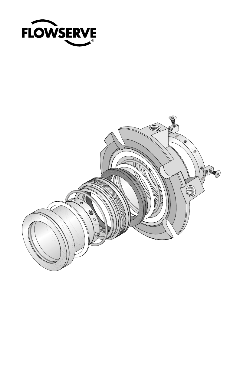
ISC1BX
Single Rotating Bellows Seal
Repair Instructions
Page 2
These instructions are written for trained, experienced technicians familiar with the basic
principles and tools involved in the installation, care and service of mechanical seals and seal
support systems. A complete reading of these instructions by personnel in contact with the
equipment is essential to safety. Incorrect installation, operation or maintenance can result in
personal injury or death to personnel and damage to the equipment.
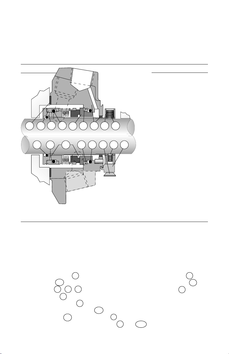
1 Nomenclature
Figure 1
G
SL
6
11
M
M1
3A
34 P
1 13910A
K 13A
CT1B
Table 1
34 Bellows Assembly
3A Mating Ring
P Mating Ring O-Ring
6 Bellows O-Ring
11 Sleeve O-Ring
G Gasket
1 Gland Assembly
1B Gland Drive Ring
CT Centering Tab
K Centering Tab Cap Screw
SL Sleeve Assembly
M Vibration Dampener
M1 Bellows Vibration Dampener
10A Driver Ring
9 Sleeve Collar
13 Cup Point Set Screw
13A Quarter Dog Set Screw
Note: Primary seal O-rings (P and 6) are
the same size and cross section.
2 Disassembly
When disassembling seal, inspect for conditions which may have caused the
need for the seal to be removed from service. If seal was removed due to
premature failure, determine what conditions caused that failure and correct any
problems prior to returning the repaired seal to service. For assistance with seal
failure analysis, please contact your Flowserve representative.
Seal Parts that are always replaced
• Bellows Assembly 34
• Mating ring 3A
• All O-rings P , 6 , 11
• Gland gasket G
• Vibration dampener M
• Bellows Vibration dampener M1
• Centering tabs CT and cap screws K
• Cup point and quarter dog set screws 13 and 13A
2
© Copyright 2000 Flowserve Corporation
Reconditionable Seal Parts
• Gland assembly 1
• Sleeve assembly SL
• Sleeve collar 9
Page 3
3 Inspection and Reconditioning
3.1 There are certain critical areas of each part where special attention should
be paid to the condition. If any of the areas listed in 3.2, 3.3 or 3.4 show signs
of wear, corrosion, or other defects that cannot be removed without affecting
the dimensional size of the surfaces by more than 0.001 to 0.002", then the
respective part should be replaced. If grit blasting is performed, it may be
necessary to polish the O-ring surfaces to achieve the required surface finish
(see 3.2A and 3.3A for the required surface finish). If any parts require machining to correct damage, please contact your Flowserve representative for
dimensional requirements, or for any other questions regarding repair.
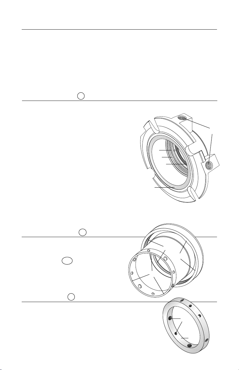
3.2 Gland Assembly 1 (Figure 2)
A Mating ring O-ring surface - Inspect for wear, fretting, nicks,
scratches, or corrosion.
Required surface finish
: 63 RMS
B Gasket surface - Remove the old gasket
and clean the gasket surface. Inspect for
nicks, scratches, or corrosion.
C Pipe taps and other threaded holes -
Inspect for damaged threads or corrosion.
Taps must be clean and free of debris and
corrosion. Re-tap as necessary.
D Bushing - Inspect for wear, breakage, or
A
E
D
loosened bond with gland. Replace using
Loctite®1 7471 Primer T and Loctite RCTM/640
or equivalent to adhere the bushing if any of
these conditions exist. A ten minute cure at
B
400°F (204°C) is required to achieve full bond strength.
If worn or corroded, contact your Flowserve representative.
E Gland drive ring - Inspect for wear or corrosion, especially at
drive flat surfaces on ID of drive ring. If worn or corroded, contact
your Flowserve representative.
3.3 Sleeve Assembly SL (Figure 3)
A O-ring surfaces - Inspect for wear, nicks,
scratches, or corrosion.
finish
: 63 RMS.
Required surface
A
B Drive Ring 10A - Inspect for wear or
corrosion, especially at drive flat
surfaces on ID of drive ring.
C
C Drive end roundness -
No greater than 0.001" TIR
B
Figure 2
Figure 3
C
3.4 Sleeve Collar 9 (Figure 4)
A Threaded holes - Inspect for thread damage and
re-tap as necessary.
B ID bore roundness - No greater than 0.002" TIR
C Set screws - Replace cup point and dog point set
screws with those included with the repair kit. Make
sure the same threaded holes are used with the same
type set screws.
1 Registered Trademark of Loctite Corporation
Figure 4
A
B
3
Page 4
4 Seal Assembly Instructions
4.1 Tools Required
•3/32", 1/8" hex key wrenches (Sizes < 2.625"); 1/8", 3/16" hex key
wrenches (Sizes 2.625" and larger)
• Silicone grease (included in repair kit)
• Ethyl alcohol or acetone and clean, lint free towel for cleaning seal faces
4.2 As part of the assembly of the seal, there are several blind fits of pins and
drive flats. It may be helpful to mark the locations of the pins or drive flats
with a felt tip marker, or to align the feature with another visible feature on
the seal to assist with assembly. All seal faces should be cleaned with ethyl
alcohol or acetone prior to placing the faces together at each respective step
in the assembly process.
4.3 Arrange O-rings by diametrical size. There are two sizes:
two of the largest size (O-rings
P and 6 ), and one of the
smallest size (O-ring 11 ).
Prior to installing each O-ring
at its respective step, lightly
lubricate with silicone
grease and stretch slightly.
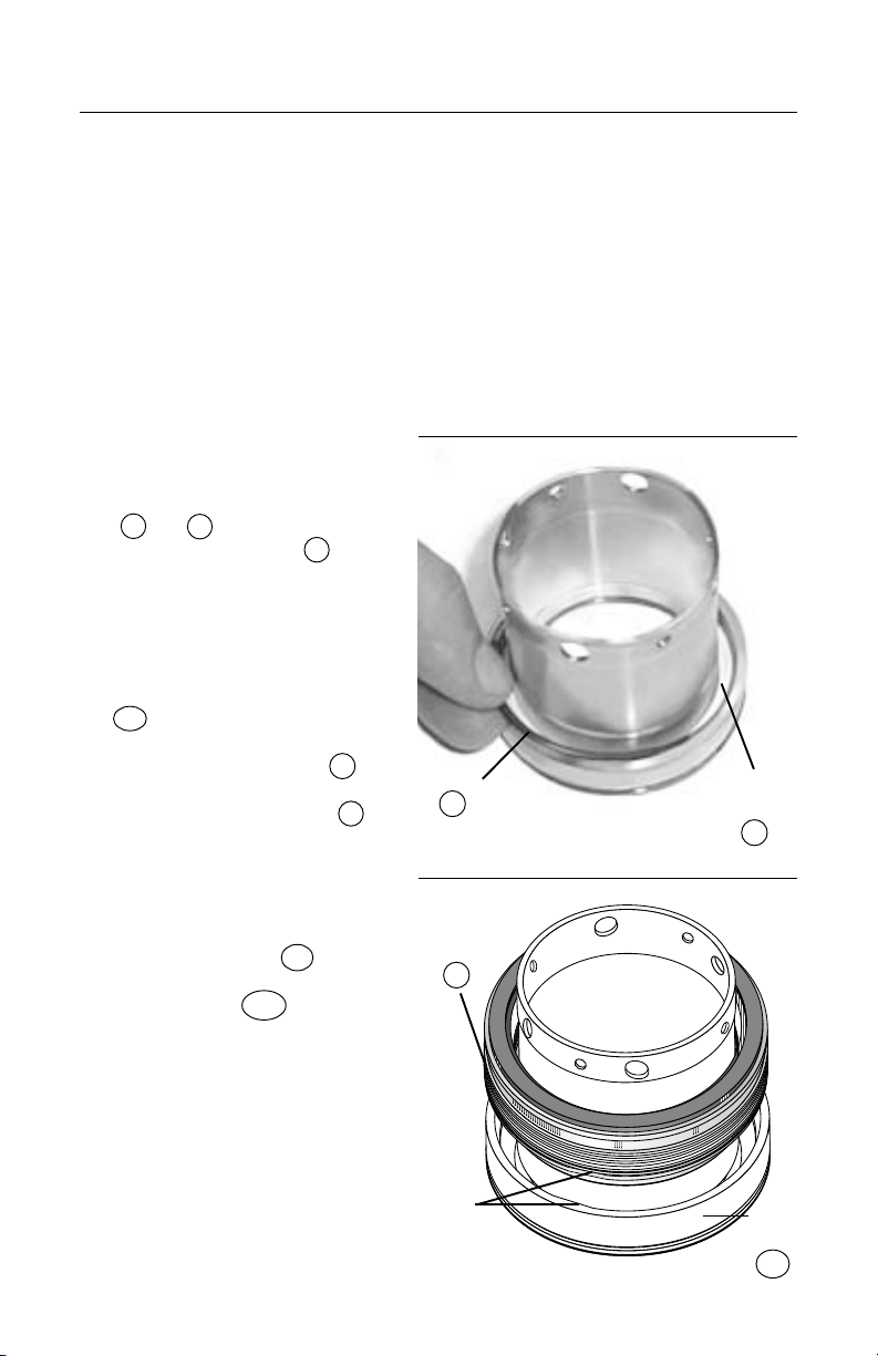
4.4 Place the sleeve assembly
SL on a flat surface with the
collar end facing up. Install
the vibration dampener M
into sleeve end housing.
Place the bellows O-ring 6
in sleeve O-ring groove
behind surface with drive flats
in sleeve. (Figure 5)
4.5 Align the two flats on the
bellows assembly 34 with
the two flats on the inside of
the drive ring 10A in the
sleeve end housing, and
press the bellows assembly
into place using finger
pressure only.
Caution: Be careful not to
over compress the bellows
assembly. (Figure 6)
O-ring
6
Bellows
Assembly
34
Drive
Flats
Figure 5
Vibration
Dampner
M
Figure 6
Drive
Ring
10A
4
Page 5

Vibration
Dampener
M1
Gland
Drive Ring
1B
O-ring
P
Figure 7
4.6 Place the mating ring O-ring
P in the gland assembly
behind the gland drive ring
1B . Place the vibration
dampener M into the groove
at the front surface of the
gland drive ring. (Figure 7)
Mating Ring
3A
Figure 8
Figure 9
4.7 Align the two flats on the
mating ring 3A with the two
flats on the inside of the
gland drive ring in the gland
assembly, and press the
mating ring in place using
finger pressure only. (Figure 8)
4.8 Place the gland/mating ring
assembly face down over the
sleeve/bellows assembly.
(Figure 9)
5
Page 6

4.9 Place the sleeve collar 9
onto the end of the sleeve
with the "Flowserve" logo
facing up. Align the quarter
dog set screws with the
smaller holes in the end of
the sleeve. On smaller seal
sizes, one of the quarter dog
set screws will be offset by
15 degrees. Align this quarter
dog set screw with the
corresponding offset hole in
the end of the sleeve. Do not
tighten any set screws at this
time. Install the centering
tabs CT and flat head cap
screws into the collar while
engaged with the gland. Be
sure to keep the collar
aligned. (Figure 10)
4.10 Using firm hand pressure,
press down on the collar to
be even with the end of the
sleeve assembly. This will in
turn press down the gland
and inner gland, compressing
the springs. While holding the
collar even with the end of
the sleeve assembly, tighten
the quarter dog set screws
into the holes in the sleeve
until snug.
Be careful not to
distort the sleeve by over
tightening the quarter dog
set screws.
(Figure 11)
Centering
Tabs
O-ring
11
Figure 10
Sleeve
Collar
Figure 11
Figure 12
4.11 Install the shaft O-ring 11
into the inside diameter
groove of the sleeve assembly. (Figure 12)
4.12 Adhere the gland gasket G
to the gland gasket surface
with a spray adhesive such
as 3M Super 77
2 Trademark of Minnesota Mining and Manufacturing Company.
6
®2
. (Figure 12)
Gland Gasket
G
Page 7

5 Static Testing
5.1 Flowserve manufacturing typically air tests the ISC at 25 psig. A pressure drop
of less than one pound at 25 psig is acceptable. To static test the seal, bolt
it to a single seal test barrel or to the equipment. Secure the cup point set
screws to the stub shaft or equipment shaft to help prevent deformation of
the centering tabs due to axial loads. The seal may be pressurized through
either of the tangential flush ports, identified with the letter "F" cast into the
gland. If the seal does not pass the static pressure test, disassemble the
seal and inspect for O-ring damage, as this is the most common cause of
static test failure.
6 Installation
6.1 Refer to the ISC Installation Instructions, FIS120, for proper seal installation.
7
Page 8

TO REORDER REFER TO
B/M #
.
F.O
The information and specifications presented in these repair instructions are believed to be accurate, but are not guaranteed by Flowserve as to
completeness or accuracy. Although Flowserve Corporation can provide general application guidelines, it cannot provide specific information
for all possible applications. The purchaser/user must therefore assume the ultimate responsibility for the proper selection, installation, operation
and maintenance of Flowserve products. Because Flowserve Corporation is continually improving and upgrading its product design, the
specifications, dimensions and information contained herein are subject to change without notice.
Flowserve Corporation Flow Solutions Division
Primary Worldwide Flow Solutions Division Locations Licensees, authorized agents, and affiliated companies located worldwide
United States
Kalamazoo, MI
Phone 616-381-2650
Fax 616-381-8368
Edmonton, Alberta
Phone 780-463-7958
Fax 780-450-1241
Canada
Scarborough, Ontario
Phone 416-292-2877
Fax 416-292-5190
Singapore Japan
Phone 65-746-4318
Fax 65-747-1963
Printed in U.S.A.
Tlaxcala
Phone 52-2-461-6791
Fax 52-2-461-6847
Sao Paulo
Phone 55-11-4066-8600
Fax 55-11-4066-70144
Netherlands
Roosendaal
Phone 31-165-581400
Fax 31-165-552622
Osaka
Phone 81-720-85-5571
Fax 81-720-85-5575
www.flowserve.com
ISO 9000
Certified
Argentina
Villa Martelli
Phone 54-11-4709-6800
Fax 54-11-4709-7072
GermanyBrazilMexico
Dortmund
Phone 49-231-6964-0
Fax 49-231-6964-248
Australia
Marayong NSW
Phone 61-2-8822-7100
Fax 61-2-9679-7511
FIS138
ORG 06/00 USA
 Loading...