

Page 1
Experience In Motion
ISC Series
Innovative Standard Cartridge seal designed
for ANSI and general purpose applications with
maximum interchangeability between designs.
Installation
Instructions
Page 2

Description
This ISC seal is a cartridge mounted mechanical seal, designed for ease
of installation and reliable operation. No seal setting dimensions are
required. Removable setting devices provide proper alignment.
The ISC seal family consists of:
ISC1PX - Single Pusher Seal stationary springs
ISC2PP - Dual Pusher Seal stationary springs
ISC1BX - Single Metal Bellows Seal rotating bellows (standard)
ISC2BB - Dual Metal Bellows Seal rotating bellows (standard)
ISC1SX - Single Metal Bellows Seal stationary bellows (optional)
ISC2SS - Dual Metal Bellows Seal stationary bellows (optional)
ISC1EX - Single Elastomer Bellows Seal
The exible stator pusher design compensates for inadvertent
misalignment of the seal chamber face. Multiple springs provide uniform
face loading and are external of the process uid, resisting clogging and
stress corrosion.
The bellows design is available in both rotating and stationary bellows
arrangements.
Rotating bellows arrangements are used when the self cleaning
feature is required and stationary bellows are used to compensate for
inadvertent misalignment of the seal chamber face.
Installation according to the following steps will assure long trouble free
life of the seal.
1 Equipment Check
1.1 Follow plant safety regulations prior to equipment disassembly:
• lock out motor and valves.
• wear designated personal safety equipment.
• relieve any pressure in the system.
• consult plant MSDS les for hazardous material regulations.
1.2 Disassemble equipment in accordance with equipment
manufacturer’s instructions to allow access to seal installation area.
1.3 Remove existing mechanical seal and gland or compression
packing and packing gland.
The images of parts shown in these instructions may differ visually from the actual
parts due to manufacturing processes that do not affect the part function or quality.
2
Page 3
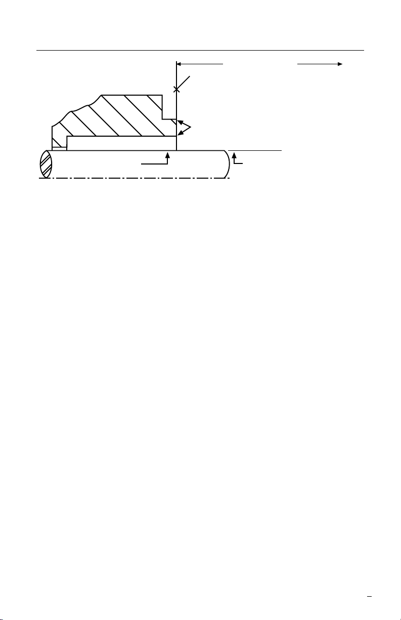
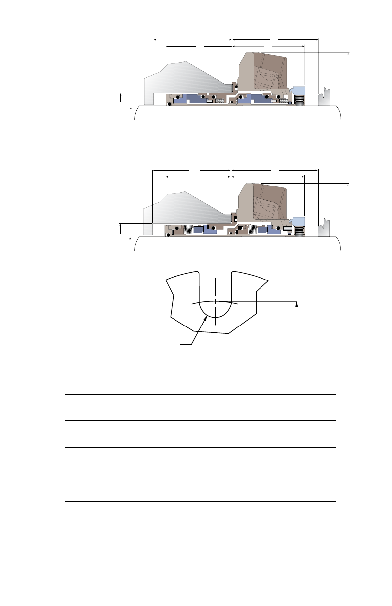
Seal Chamber Requirements Figure 1
To first obstruction
Face of seal housing to be square to the axis
of the shaft to within 0.013 mm per millimeter
(0.0005 inches) of seal chamber bore FIM and
have a √1.6
μm (63 μinch) R finish or better
a
Gland pilot can be at either of these
register locations, concentric to within
0.13 mm (0.005 inch) FIM of shaft or sleeve OD
Seal housing bore to have √3.2 μm
(125 μinch) R finish or better
Sleeve or shaft finish to be
0.8 μm (32 μinch) R or better
a
a
Shaft or sleeve OD
+0.000 mm (+0.000 inch)
-0.050 mm (-0.002 inch) ANSI
+0.000 mm (+0.000 inch) API 610/682
-0.025 mm (- 0.001 inch) DIN/ISO
• Bearings must be in good condition
• Maximum lateral or axial movement of shaft (end play) = 0.25 mm (0.010 inch) FIM
• Maximum shaft runout at face of seal housing = 0.05 mm (0.002 inch) FIM
• Maximum dynamic shaft deflection at seal housing = 0.05 mm (0.002 inch) FIM
If the pump condition exceeds the above criteria (including consideration for thermal growth), consult
Flowserve Application Engineering for recommendations to avoid seal performance compromises.
1.4 Make sure the shaft or sleeve and the seal housing face are clean
and free of burrs, cuts, dents, or corrosion that might cause leakage
past the sleeve gasket or gland gasket. Replace worn shaft or
sleeve. Remove sharp edges from keyways and threads.
1.5 Check equipment dimensions to ensure that they are within the
specications shown in Figures 1 and 2. Critical dimensions from
Figure 2 include:
• Box Bore (ØC)
• Box Depth (G)(Q)
• Distance to First Obstruction (K)
• Pump Frame accomodates Gland OD (ØE)
1.6 Check gland bolting to ensure the bolt diameter and bolt circle
conform to the dimensions shown in Figure 2. Check gland bolt
length to ensure adequate thread engagement for the actual seal
gland.
1.7 Check gland bolt length to ensure adequate thread engagement
for the actual seal gland. Gland dimensions are provided in the
drawing that accompanied the seal.
1.8 Handle the ISC with care, it is manufactured to precise tolerances.
The sealing faces of the ISC seal are the rotating and stationary
faces. They are lapped at to within three helium light bands (34.8
millionths of an inch). Keep the seal faces perfectly clean at all
times.
3
Page 4
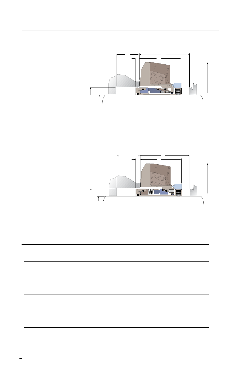
ISC Dimensional Data Figure 2
ISC1PX
Single Pusher
ISC1BX
Single Metal Bellows
ØC
ØA
Shaft Size
& Seal Size
ØC
ØA
Shaft Size
& Seal Size
G
F
K
J
ØE
G
F
K
J
ØE
All Dimensions millimeter
A C E F G J K L M
Shaft & Box Bore Gland Seal Box Depth Seal Dist. to Bolt Bolt
Seal Size (Min) (Max) OD (Min) Depth (Min) Extension Obst. Dia. Circle Slot
25 41.28 47.50 93.7 - 95.3 5.38 6.96 48.59 50.17 69.85 11.18
28 44.45 50.80 93.7 - 95.3 5.38 6.96 48.59 50.17 73.03 11.18
30 48.01 57.02 106.4 - 108.0 5.38 6.96 48.59 50.17 79.38 14.27
33 50.80 60.33 109.7 - 111.3 5.38 6.96 48.59 50.17 82.55 14.27
35 50.80 60.33 109.7 - 111.3 5.38 6.96 48.59 50.17 82.55 14.27
38 57.15 64.14 119.1 - 120.7 5.38 6.96 50.11 51.69 95.25 14.27
40 60.33 70.61 119.1 - 120.7 5.13 6.71 50.11 51.69 95.25 14.27
43 63.50 73.03 125.5 - 127.0 5.13 6.71 50.11 51.69 98.43 14.27
45 66.68 73.03 125.5 - 127.0 5.13 6.71 50.11 51.69 98.43 14.27
48 67.06 73.41 136.4 - 137.9 5.13 6.71 50.11 51.69 97.99 14.27
50 69.85 76.96 127.0 - 130.0 5.13 6.71 50.11 51.69 104.65 17.48
53 73.03 79.38 150.9 - 152.4 5.13 6.71 50.11 51.69 112.78 19.05
55 79.38 93.65 160.5 - 162.1 5.13 6.71 50.11 51.69 123.83 19.05
60 79.38 94.62 160.5 - 162.1 5.13 6.71 50.11 51.69 123.83 19.05
65 89.92 98.81 179.5 - 181.0 1.93 3.51 53.42 54.99 127.00 17.48
70 95.25 109.52 182.6 - 184.2 5.18 6.76 69.24 70.82 142.88 22.35
4
Page 5
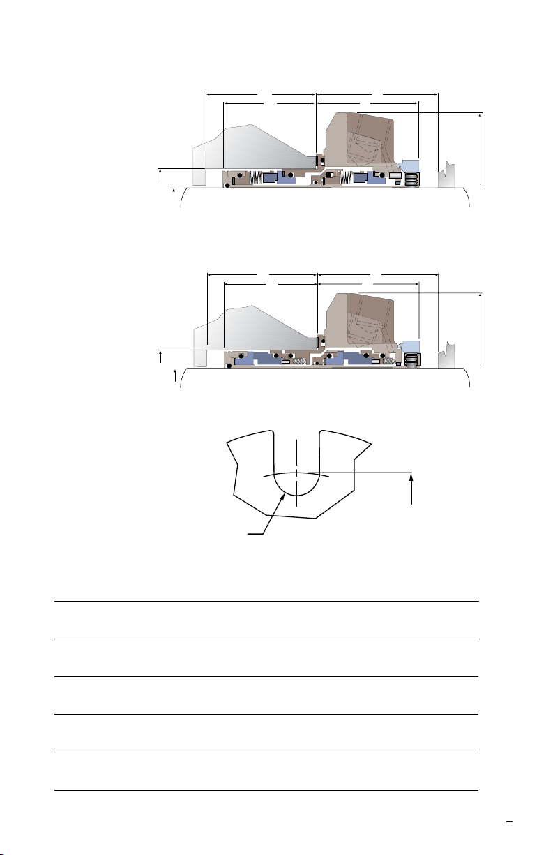
ISC2BB
Dual Metal Bellows
G
F
K
J
ØC
ØA
Shaft Size
& Seal Size
ISC2PP
G
F
K
J
Dual Pusher
ØC
ØA
Shaft Size
& Seal Size
Slotted Gland Detail
ØL
ØM
A C E F G J K L M
Shaft & Box Bore Gland Seal Box Depth Seal Dist. to Bolt Bolt
Seal Size (Min) (Max) OD (Min) Depth (Min) Extension Obst. Dia. Circle Slot
25 41.28 47.50 93.7 - 95.3 46.69 48.26 52.37 53.95 69.85 11.18
28 44.45 50.80 93.7 - 95.3 46.69 48.26 52.37 53.95 73.03 11.18
30 48.01 57.02 106.4 - 108.0 46.69 48.26 52.37 53.95 79.38 14.27
33 50.80 60.33 109.7 - 111.3 46.69 48.26 52.37 53.95 82.55 14.27
35 50.80 60.33 109.7 - 111.3 46.69 48.26 52.37 53.95 82.55 14.27
38 57.15 64.14 119.1 - 120.7 48.34 49.91 53.90 55.47 95.25 14.27
40 60.33 70.61 119.1 - 120.7 48.34 49.91 53.90 55.47 95.25 14.27
43 63.50 73.03 125.5 - 127.0 48.34 49.91 53.90 55.47 98.43 14.27
45 66.68 73.03 125.5 - 127.0 48.34 49.91 53.90 55.47 98.43 14.27
48 67.06 73.41 136.4 - 137.9 48.34 49.91 53.90 55.47 97.99 14.27
50 69.85 76.96 127.0 - 130.0 48.34 49.91 53.90 55.47 104.65 17.48
53 73.03 79.38 150.9 - 152.4 48.34 49.91 53.90 55.47 112.78 19.05
55 79.38 93.65 160.5 - 162.1 48.34 49.91 53.90 55.47 123.83 19.05
60 79.38 94.62 160.5 - 162.1 48.34 49.91 53.90 55.47 123.83 19.05
65 89.92 98.81 179.5 - 181.0 45.06 46.63 57.20 58.78 127.00 17.48
70 95.25 109.52 182.6 - 184.2 61.70 63.27 73.81 75.39 142.88 22.35
ØE
ØE
5
Page 6

ISC Dimensional Data
G
F
K
J
ISC1PX
Single Pusher
ØC
ØA
Shaft Size
& Seal Size
G
F
K
J
ØE
ISC1BX
Single Metal Bellows
ØC
ØA
Shaft Size
& Seal Size
Q
P J
K
ØE
ISC1EX
Single Elastomer Bellows*
ØC
ØA
Shaft Size
All Dimensions inch
A C E F G J K L M P* Q*
& Seal Size
Shaft & Box Bore Gland Seal Box Depth Seal Dist. to Obst. Bolt Bolt Seal Box Depth
Seal Size (Min) (Max) OD Depth (Min) Extension (Min) Circle Slot Dia. Depth (Min)
1.000 1.625 1.875 3.69 - 3.75 0.212 0.274 1.913 1.975 2.750 0.440 0.812 0.874
1.125 1.750 2.000 3.69 - 3.75 0.212 0.274 1.913 1.975 2.875 0.440 0.962 1.024
1.250 1.890 2.245 4.19 - 4.25 0.212 0.274 1.913 1.975 3.125 0.562 N/A N/A
1.375 2.000 2.375 4.32 - 4.38 0.212 0.264 1.913 1.975 3.250 0.440 1.127 1.189
1.437 2.250 2.688 4.72 - 4.78 0.222 0.284 1.958 2.020 3.750 0.560 N/A N/A
1.500 2.250 2.525 4.69 - 4.75 0.202 0.264 1.973 2.035 3.750 0.560 1.152 1.214
1.625 2.375 2.780 4.69 - 4.75 0.202 0.264 1.973 2.035 3.750 0.560 1.152 1.214
1.750 2.500 2.875 4.94 - 5.00 0.202 0.264 1.973 2.035 3.875 0.560 1.152 1.214
1.875 2.625 2.875 4.94 - 5.00 0.202 0.264 1.973 2.035 3.875 0.560 1.153 1.214
1.937 2.750 3.030 5.09 - 5.15 0.202 0.264 1.973 2.035 4.120 0.688 N/A N/A
2.000 2.750 3.030 5.09 - 5.15 0.202 0.264 1.973 2.035 4.120 0.688 1.152 1.214
2.125 2.875 3.125 5.94 - 6.00 0.202 0.264 1.973 2.035 4.440 0.750 1.092 1.154
2.250 3.000 3.318 5.94 - 6.00 0.206 0.268 1.973 2.035 4.440 0.750 N/A N/A
2.375 3.125 3.687 6.32 - 6.38 0.202 0.264 1.973 2.035 4.875 0.750 1.287 1.349
2.437 3.375 3.687 6.32 - 6.38 0.233 0.295 1.942 2.004 4.875 0.750 N/A N/A
2.500 3.375 3.687 6.32 - 6.38 0.202 0.264 1.973 2.035 4.875 0.750 1.287 1.349
2.625 3.625 4.312 7.19 - 7.25 0.204 0.266 2.726 2.788 5.625 0.880 1.129 1.191
2.750 3.750 4.312 7.19 - 7.25 0.204 0.266 2.726 2.788 5.625 0.880 1.129 1.191
*Dimensional items P & Q refer to Single Elastomer Bellows only
ØE
6
Page 7
ISC2PP
Dual Pusher
G
F
K
J
ØC
ØA
Shaft Size
& Seal Size
K
J
ISC2BB
G
F
Dual Metal Bellows
ØC
ØA
Shaft Size
& Seal Size
Slotted Gland Detail
ØL
ØM
A C E F G J K L M
Shaft & Box Bore Gland Seal Box Depth Seal Dist. to Obst. Bolt Bolt
Seal Size (Min) (Max) OD Depth (Min) Extension (Min) Circle Slot Dia.
1.000 1.625 1.875 3.69 - 3.75 1.838 1.900 2.062 2.124 2.750 0.440
1.125 1.750 2.000 3.69 - 3.75 1.838 1.900 2.062 2.124 2.875 0.440
1.250 1.890 2.245 4.19 - 4.25 1.838 1.900 2.062 2.124 3.125 0.562
1.375 2.000 2.375 4.32 - 4.38 1.838 1.900 2.062 2.124 3.250 0.440
1.437 2.250 2.688 4.72 - 4.78 1.903 1.965 2.122 2.184 3.750 0.560
1.500 2.250 2.525 4.69 - 4.75 1.903 1.965 2.122 2.184 3.750 0.560
1.625 2.375 2.780 4.69 - 4.75 1.903 1.965 2.122 2.184 3.750 0.560
1.750 2.500 2.875 4.94 - 5.00 1.903 1.965 2.122 2.184 3.875 0.560
1.875 2.625 2.875 4.94 - 5.00 1.903 1.965 2.122 2.184 3.875 0.560
1.937 2.750 2.030 5.09 - 5.15 1.903 1.965 2.122 2.184 4.120 0.688
2.000 2.750 3.030 5.09 - 5.15 1.903 1.965 2.122 2.184 4.120 0.688
2.125 2.875 3.125 5.94 - 6.00 1.903 1.965 2.122 2.184 4.440 0.750
2.250 3.000 3.318 5.94 - 6.00 1.903 1.965 2.122 2.184 4.400 0.750
2.375 3.125 3.687 6.32 - 6.38 1.903 1.965 2.122 2.184 4.875 0.750
2.437 3.375 3.687 6.32 - 6.38 1.934 1.996 2.091 2.153 4.875 0.750
2.500 3.375 3.687 6.32 - 6.38 1.903 1.965 2.122 2.184 4.875 0.750
2.625 3.625 4.312 7.19 - 7.25 2.429 2.491 2.906 2.968 5.625 0.880
2.750 3.750 4.312 7.19 - 7.25 2.429 2.491 2.906 2.968 5.625 0.880
ØE
ØE
7
Page 8

2 ISC Installation - Single Seal Design
Note: No seal setting measurements are needed to install the seal.
Instructions are for vertically split case end-suction ANSI pumps.
Modication of the procedure may be required for other style
pumps. Consult Flowserve.
2.1 Tools needed for installation:
• An open end wrench for the gland bolt nuts
• 1/8" Allen wrench (provided)
• 3/16" Allen wrench (provided) for sizes >60 mm (>2.500")
2.2 Lubricate the shaft or
sleeve lightly with silicone
Bearing Frame
Setting Device
lubricant unless otherwise
specied.
2.3 Tighten the setting device
cap screws
2.4 Install the complete ISC
cartridge assembly onto the
shaft or sleeve with the
setting devices near the
bearing housing.
See Figure 3.
Bearing Frame
8
Figure 3
Figure 4
Pump
Back
Plate
2.5 Install the
pump back
plate (seal
chamber) and
bolt it in place
on the bearing
frame. See
Figure 4.
Page 9

2.5 Position the ISC with the gland tight against the seal chamber face.
If equipment conditions allow, position gland with the outlet port or
plugged ush port as close to the 12:00 o'clock position as possible.
See Sections 3 and 4 for further piping considerations. Otherwise turn
the gland so that the vent tap is as close to the 12:00 o’clock position
as possible and so that the ush piping will clear the bearing frame.
Caution: Setting devices should not be removed or loosened before tighten ing the gland bolts and tightening the set screws to the shaft.
Tighten the gland nuts evenly in a diagonal sequence. Do not over
tighten the gland nuts, as this can warp seal parts and cause leakage.
Conrm adequate thread engagement before nal torque setting.
The suggested ISC minimum torque
values are as follows for seals with
these shaft sizes (in inches):
15 ft-lbs (20 N-m) 20 ft-lbs (27 N-m)
1.000 2.125
to to
2.000 2.750
2.6 Assemble the pump. Avoid pipe
strain. Align coupling properly.
2.7 With the impeller, shaft, coupling,
and bearings in their nal operating
positions, tighten the drive collar
Figure 5
set screws. See Figure 5.
Suggested minimum torque values for set screws are as follows:
Shaft Sizes 25 - 60 mm (1.000 - 2.500 inches)
1
" 4.5 N-m (40 inch-lbs)
4
Shaft Sizes 67 - 70 mm (2.625 - 2.750 inches)
3
" 13.6 N-m (120 inch-lbs)
8
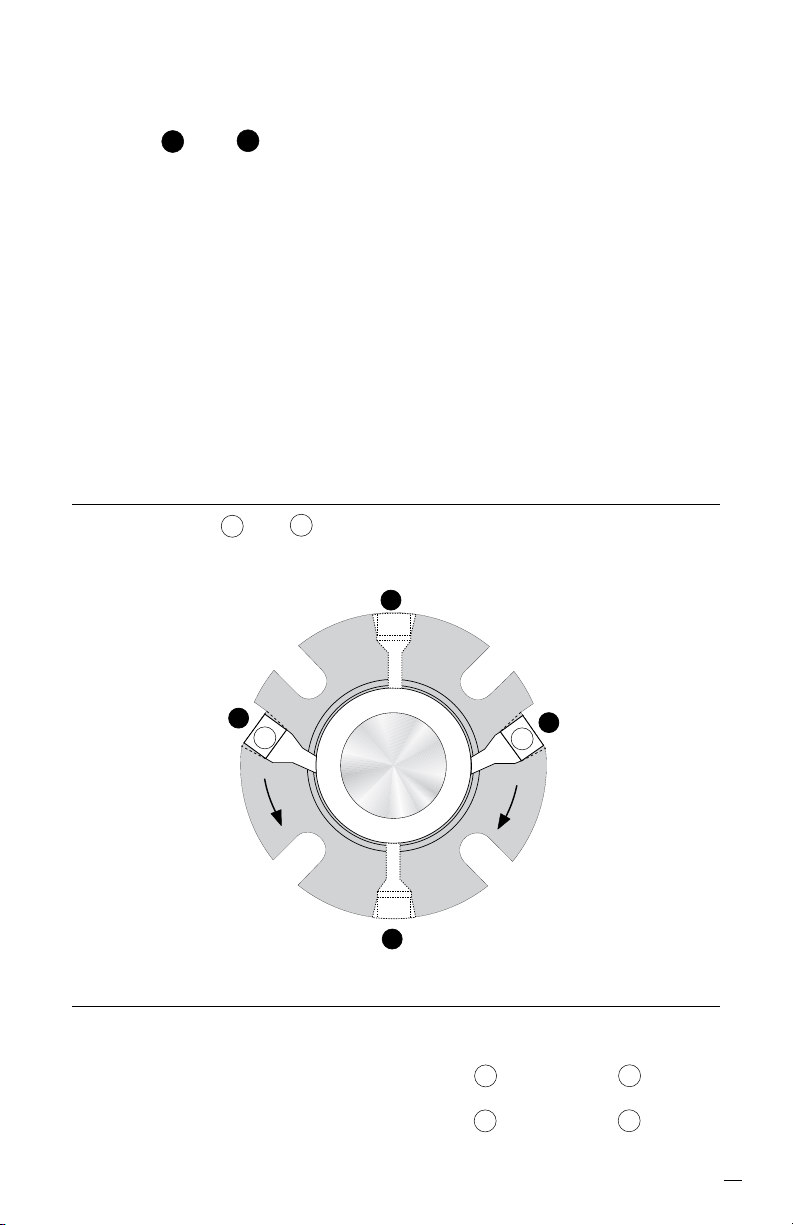
2.8 Caution: Remove the setting
devices from the drive collar.
See Figure 6. Save these and the
fasteners for future use when the
pump impeller is reset or when the
seal is removed for repairs.
2.9 Turn the shaft by hand to ensure
unobstructed operation.
2.10 See Operational
Recommendations before start-up.
Figure 6
9
Page 10

CW
Rotation
F
D
F
Q
CCW
Rotation
3 Single Seal Piping and OperationalRecommendation
3.1 Install an adequate seal ush system. The ISC requires a clean
cool environment for maximum seal life. With a clean cool product,
use a bypass ush from the pump discharge (piping plan 11*) or a
bypass ush to the pump suction (piping plan 13). With clean hot
products use a bypass ush through a cooler (piping plan 21). With
abrasive products or products that are incompatible with the seal,
use a ush from a clean external source (piping plan 32).
*Note: All piping plan designations used in these instructions are from API 682.
for the corresponding ASME B73 piping plan designation, please add a
"73" in front of the referenced piping plan.
a
b
Shaft rotation from exposed end of gland Figure 7
For Piping Plans 11, 21 and 32:
Shaft Rotation Inlet Plugged
(from exposed end of gland) Port
Clockwise (CW) Port b Port a
Counterclockwise (CCW) Port a Port b
For Piping Plan 13:
Shaft Rotation Outlet Plugged
(from exposed end of gland) Port
Clockwise (CW) Port a Port b
Counterclockwise (CCW) Port b Port a
10
Page 11
CW
Rotation
F
D
F
Q
CCW
Rotation
3.2 Use ush port that coincides with gland markings and direction of
equipment rotation. Plug extra NPT opposite of ush. See Figure 7.
3.3 Taps Q and D in the gland are quench and drain ports used for
uid quenching, ush plan 62. If they are not used, they should be
plugged with pipe plugs.
3.4 Remove lock outs on pump and valves.
3.5 Do not start up the equipment dry to check motor rotation or for any
other reason. Open valves to ood pump with product uid. Ensure
that the seal ush system is operating. Vent air from the casing of
the pump and the seal chamber before start-up.
3.6 Observe the start-up. If the seal runs hot or squeals, check the
seal ush system. Do not allow the equipment to run for any
extended time if the seal gets hot or squeals.
4 Dual Seal Piping and Operational Recommendations
4.1 Flush taps a and b in the gland are barrier uid inlet and
outlet ports. Use Figure 8 to determine which ports to use as inlet
and outlet.
a
Shaft rotation from exposed end of gland Figure 8
Inlet Outlet
Clockwise (CW) Port b Port a
b
Counterclockwise (CCW) Port a Port b
11
Page 12
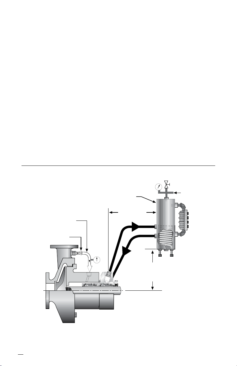
4.2 For dual pressurized seal (double seal) operation, supply a clean
compatible barrier uid to the inlet port at a pressure at least
170 kPa (25 psi) above the seal chamber pressure. See Figure 9.
The pressure of the barrier uid must not exceed the recommended
maximum pressure. Flowserve can supply information on barrier
uid ow requirements based on seal size, product temperature,
barrier uid characteristics, and shaft speed.
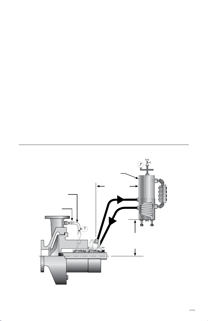
4.3 For dual unpressurized (tandem seal) operation, supply a clean
compatible buffer uid to the inlet port at a pressure below the seal
chamber pressure. See Figure 10. The pressure in the seal
chamber must not exceed the recommended maximum pressure.
Flowserve can supply information on buffer uid ow requirements
based on seal size, product temperature, buffer uid characteristics,
and shaft speed.
Double ISC with Supply Tank Figure 9
12
Bypass
Flush to
Gland
Flush Port
Orifice
Option
Supply Tank
Assembly with
Cooling Coils
1.2 m (4 feet)
maximum
Pressure
Source
0.45 - 0.6 m
(1.5 - 2 feet)
minimum
Page 13
4.4 The Flowserve Supply Tank is designed to work with the ISC Dual
Seal to form a self-contained sealing system. The new circulating
feature in the ISC provides a positive barrier uid ow from the seal
cavity to the Supply Tank and back to the seal. In most cases the
natural cooling of the piping and tank are adequate to remove seal
generated heat. Cooling coils are available with the Supply Tank to
increase heat dissipation. The Supply Tank can be used with the
ISC dual seal in both the dual pressurized or dual unpressurized
operating modes.
Recommendation: For enhanced seal performance and reduced
coking, use DuraClear as a barrier uid. Refer to DuraClear brochure
FSD123 or contact a Flowserve seal application engineer for further
details.
Tandem ISC with Supply Tank Figure 10
Bypass
Flush to
Gland
Flush Port
Orifice
Option
Supply Tank
Assembly with
Cooling Coils
1.2 m (4 feet)
maximum
Vent to Vapor
Recovery
0.45 - 0.6 m
(1.5 - 2 feet)
minimum
13
Page 14

5 Operational Recommendations
5.1 Do not exceed corrosion limits. The ISC is designed to resist
corrosion by most chemicals. However, do not expose the ISC
materials of construction to products outside of their corrosion limits.
The ISC assembly drawing lists the materials of construction.
Consult Flowserve for chemical resistance recommendations.
5.2 Do not exceed the recommended maximum pressure and
speed limits shown in the ISC brochure.
5.3 Do not exceed the temperature limits of the ISC. The materials of
construction are listed on the ISC assembly drawing. For dual seals
using supply tanks with cooling coils, turn on cooling water to the
supply tank before start-up.
5.4 Do not start up or run the ISC dry. Buffer/barrier uid must be in
the seal cavity for dual seals at all times during pump operation.
Process uid must be in the pump volute at all times during single
seal operation.
14
Page 15

6 Repairs
This product is a precision sealing device. The design and dimension
tolerances are critical to seal performance. Only parts supplied by
Flowserve should be used to repair a seal. To order replacement parts,
refer to the part code and B/M number. A spare backup seal should be
stocked to reduce repair time.
When seals are returned to Flowserve for repair, decontaminate the
seal assembly and include an order marked "Repair or Replace." A
signed certicate of decontamination must be attached. A Material
Safety Data Sheet (MSDS) must be enclosed for any product that
came in contact with the seal. The seal assembly will be inspected and, if
repairable, it will be rebuilt, tested, and returned.
15
Page 16

TO REORDER REFER TO
flowserve.com
USA and Canada
Kalamazoo, Michigan USA
Telephone: 1 269 381 2650
Telefax: 1 269 382 8726
Europe, Middle East, Africa
Roosendaal, the Netherlands
Telephone: 31 165 581400
Telefax: 31 165 554590
Asia Pacific
Singapore
Telephone: 65 6544 6800
Telefax: 65 6214 0541
Latin America
Mexico City
Telephone: 52 55 5567 7170
Telefax: 52 55 5567 4224
B/M #
F.O
.
FIS120eng REV 06/12 Printed in USA
To find your local Flowserve representative
and find out more about Flowserve Corporation,
visit www.flowserve.com
Flowserve Corporation has established industry leadership in the design and manufacture of its products. When
properly selected, this Flowserve product is designed to perform its intended function safely during its useful life.
However, the purchaser or user of Flowserve products should be aware that Flowserve products might be used
in numerous applications under a wide variety of industrial service conditions. Although Flowserve can provide
general guidelines, it cannot provide specific data and warnings for all possible applications. The purchaser/user
must therefore assume the ultimate responsibility for the proper sizing and selection, installation, operation, and
maintenance of Flowserve products. The purchaser/user should read and understand the Installation Instructions
included with the product, and train its employees and contractors in the safe use of Flowserve products in connection
with the specific application.
While the information and specifications contained in this literature are believed to be accurate, they are supplied for
informative purposes only and should not be considered certified or as a guarantee of satisfactory results by reliance
thereon. Nothing contained herein is to be construed as a warranty or guarantee, express or implied, regarding any
matter with respect to this product. Because Flowserve is continually improving and upgrading its product design,
the specifications, dimensions and information contained herein are subject to change without notice. Should any
question arise concerning these provisions, the purchaser/user should contact Flowserve Corporation at any one of
its worldwide operations or offices.
© 2012 Flowserve Corporation
 Loading...