

FloTech FT300, FT311, FT310, FT301, FT313 Instruction Manual
...
Instruction Manual 10158
Trailer Mounted Sockets
PRODUCT DESCRIPTIONS:
These instructions cover the following FloTech products:
FT300 / FT310 API Compatible Optic Socket (6 pin 3 J-Slot)
FT301 / FT311 API Compatible Thermistor Socket (US 8pin 4 J-Slot)
FT302 / FT312 API Compatible Float Socket (7 pin J560 type)
FT303 / FT313 Optic Contact Pattern with Thermistor J Slot (6 pin 4 J-Slot)
FT304 / FT314 Canadian / Euro Thermistor Socket (10 pin 4 J-Slot)
FT305 / FT315 Old Style Thermistor ( 7 pin J560 type)
FT306 / FT316 Optic Western Canada (7 pin J560 type)
FT307 / FT317 Optic / Thermistor Canada (6 pin 4 J-Slot)
FloTech sockets are mechanically and functionally compatible with API 1004 Cargo Tank
Bottom Loading Recommended Practice. Socket faceplate and contact components are
interchangeable with Scully and Civacon socket bodies. Civacon is the registered trademark of
Civacon / Dover Corporation.
INSTALLATION INSTRUCTIONS:
Sockets are to be mounted on the same side of the trailer as the bottom loading equipment.
Sockets are normally located within 3 feet of the bottom loading adapters so the rack plug and
cord will reach the socket without over stretching the cord. Remove the socket faceplate and
hardware packet and set aside. Use the socket body as a template to drill two 11/32” holes as
shown in Diagram 1. Mount the socket body to the trailer using two 5/16 bolt and lock
washers. Make sure the grounding wire, large eyelet end is fastened under one of the 5/16
bolts.
Rev: Jan 2011 PH: 513 874 8499 FX: 513 874 8399 Page 1
4690 Interstate Dr. Suite F, Cincinnati, OH 45246
Dixon Bayco
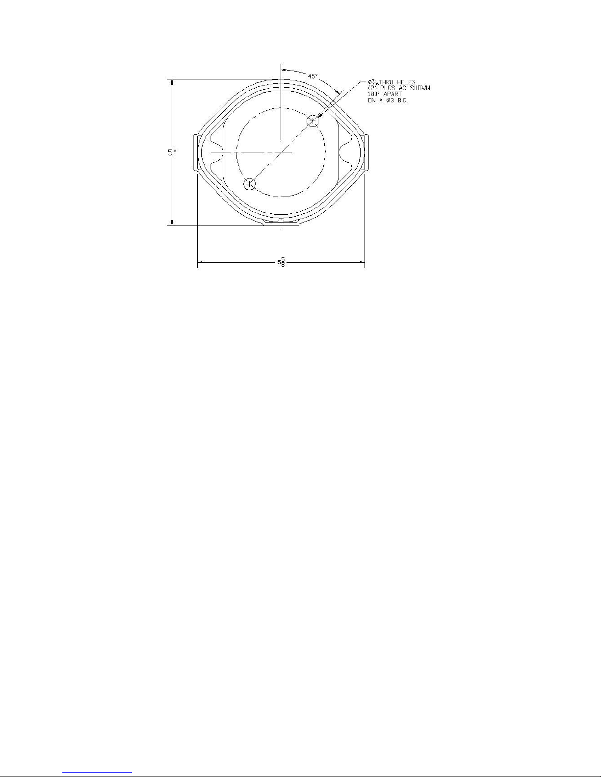
DIAGRAM 1
WIRING INSTRUCTIONS:
When wiring the sockets to an onboard monitor it is highly recommended using FloTech
FT401 jacketed 5-conductor cable when wiring a new system. FloTech cable is designed to
be oil, UV, and abrasion resistant. We incorporate a noble tin plated stranded copper wire
which resists corrosion. These features will provide years of reliable service.
After all sensors are mounted in each compartment, align the conduit openings so they face
the roll over rail. Thread in cable glands and pull a length of cable through the conduit
openings between each sensor. Cut to length leaving approximately 8 inches extra length
exiting the top of each probe holder.
All socket cables must enter or leave through one of the ½ NPT openings. Use FloTech
FT402 ½ NPT cable glands to ensure a water tight seal. Unused conduit openings must have
a ½ NPT pipe plug installed. Use pipe dope on all ½ NPT threads to ensure a water tight seal.
Wire the sockets according to diagram 2 below. Double check your wiring connection when
complete. NOTE: It is highly recommended to use a small amount of Silicone RTV sealant
in each crimp connection. Fill the FloTech butt end crimps with Silicone RTV sealant prior
to inserting the wires then crimp. This will provide a watertight and vibration resistant
connection.
When wiring is complete, replace each sensor cap and o-ring. CAUTION: Do not pinch a
sensor wire when installing the cap.
For Technical Assistance Call 877 582 3569
Rev: Jan 2011 PH: 513 874 8499 FX: 513 874 8399 Page 2
4690 Interstate Dr. Suite F, Cincinnati, OH 45246
Dixon Bayco
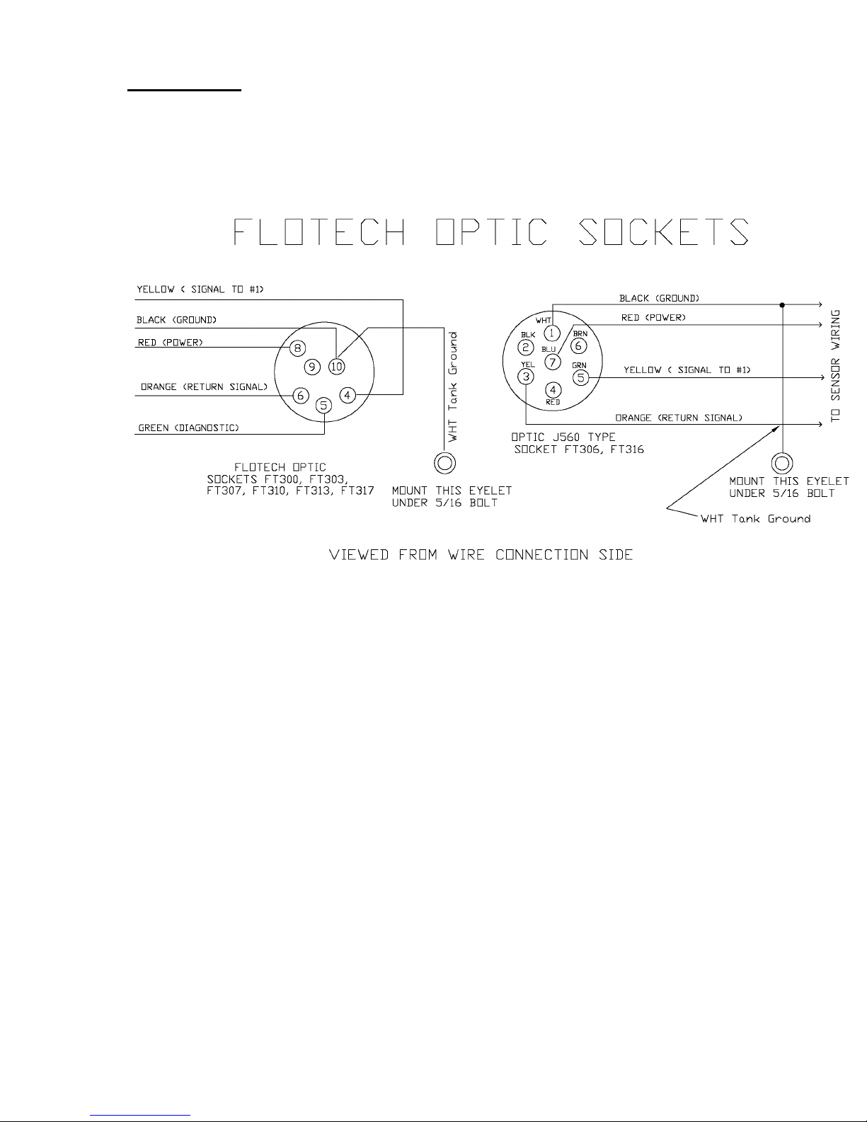
DIAGRAM 2
Dixon Bayco
4690 Interstate Dr. Suite F, Cincinnati, OH 45246
Rev: Jan 2011 PH: 513 874 8499 FX: 513 874 8399 Page 3
 Loading...