

Page 1
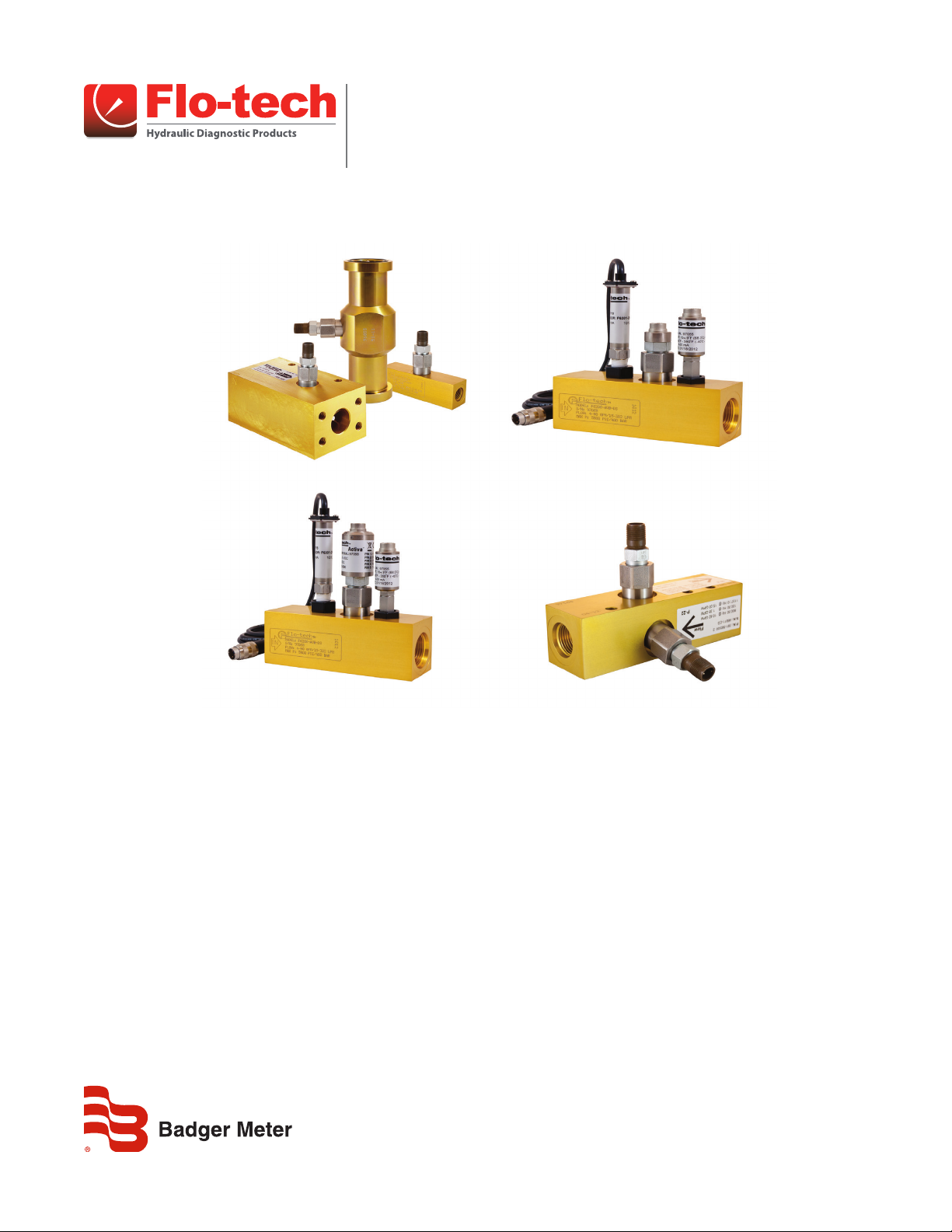
Turbine Flow Sensors
Activa, Ultima, Classic and Quad
SEN-UM-00987-EN-04 (March 2019)
User Manual
Page 2

Turbine Flow Sensors, Activa, Ultima, Classic and Quad
CONTENTS
Introduction. . . . . . . . . . . . . . . . . . . . . . . . . . . . . . . . . . . . . . . . . . . . . . . . . . . . . . . . . . . . . . . . . . . . . . . . . 3
Operating Principle . . . . . . . . . . . . . . . . . . . . . . . . . . . . . . . . . . . . . . . . . . . . . . . . . . . . . . . . . . . . . . . . . . . . 4
Installation. . . . . . . . . . . . . . . . . . . . . . . . . . . . . . . . . . . . . . . . . . . . . . . . . . . . . . . . . . . . . . . . . . . . . . . . . . 4
Installation Recommendations . . . . . . . . . . . . . . . . . . . . . . . . . . . . . . . . . . . . . . . . . . . . . . . . . . . . . . . . . . 5
Electrical Connections for Standard Magnetic Pickup. . . . . . . . . . . . . . . . . . . . . . . . . . . . . . . . . . . . . . . . . . . . 5
Electrical Connections for IFC (Intelligent Frequency Converter). . . . . . . . . . . . . . . . . . . . . . . . . . . . . . . . . . . . . 6
Electrical Connections for Optional Pressure and Temperature Sensors . . . . . . . . . . . . . . . . . . . . . . . . . . . . . . . . 7
Operation . . . . . . . . . . . . . . . . . . . . . . . . . . . . . . . . . . . . . . . . . . . . . . . . . . . . . . . . . . . . . . . . . . . . . . . . . . 8
General . . . . . . . . . . . . . . . . . . . . . . . . . . . . . . . . . . . . . . . . . . . . . . . . . . . . . . . . . . . . . . . . . . . . . . . . . 8
Flow Sensors with IFC Option . . . . . . . . . . . . . . . . . . . . . . . . . . . . . . . . . . . . . . . . . . . . . . . . . . . . . . . . . . . 8
Maintenance . . . . . . . . . . . . . . . . . . . . . . . . . . . . . . . . . . . . . . . . . . . . . . . . . . . . . . . . . . . . . . . . . . . . . . . . 8
Troubleshooting . . . . . . . . . . . . . . . . . . . . . . . . . . . . . . . . . . . . . . . . . . . . . . . . . . . . . . . . . . . . . . . . . . . . . . 9
Dimensions . . . . . . . . . . . . . . . . . . . . . . . . . . . . . . . . . . . . . . . . . . . . . . . . . . . . . . . . . . . . . . . . . . . . . . . . 10
Activa Series. . . . . . . . . . . . . . . . . . . . . . . . . . . . . . . . . . . . . . . . . . . . . . . . . . . . . . . . . . . . . . . . . . . . . 10
Ultima Series . . . . . . . . . . . . . . . . . . . . . . . . . . . . . . . . . . . . . . . . . . . . . . . . . . . . . . . . . . . . . . . . . . . . 10
Classic Series . . . . . . . . . . . . . . . . . . . . . . . . . . . . . . . . . . . . . . . . . . . . . . . . . . . . . . . . . . . . . . . . . . . . 10
Quad Series . . . . . . . . . . . . . . . . . . . . . . . . . . . . . . . . . . . . . . . . . . . . . . . . . . . . . . . . . . . . . . . . . . . . . 11
Flow vs. Pressure Drop Charts. . . . . . . . . . . . . . . . . . . . . . . . . . . . . . . . . . . . . . . . . . . . . . . . . . . . . . . . . . . . . 11
Activa and Ultima Series . . . . . . . . . . . . . . . . . . . . . . . . . . . . . . . . . . . . . . . . . . . . . . . . . . . . . . . . . . . . . 11
Classic Series . . . . . . . . . . . . . . . . . . . . . . . . . . . . . . . . . . . . . . . . . . . . . . . . . . . . . . . . . . . . . . . . . . . . 11
Quad Series . . . . . . . . . . . . . . . . . . . . . . . . . . . . . . . . . . . . . . . . . . . . . . . . . . . . . . . . . . . . . . . . . . . . . 11
Specications . . . . . . . . . . . . . . . . . . . . . . . . . . . . . . . . . . . . . . . . . . . . . . . . . . . . . . . . . . . . . . . . . . . . . . . 12
Activa and Ultima Sensor Arrays . . . . . . . . . . . . . . . . . . . . . . . . . . . . . . . . . . . . . . . . . . . . . . . . . . . . . . . . 12
Classic Flow Sensor . . . . . . . . . . . . . . . . . . . . . . . . . . . . . . . . . . . . . . . . . . . . . . . . . . . . . . . . . . . . . . . . 13
Quad Flow Sensors . . . . . . . . . . . . . . . . . . . . . . . . . . . . . . . . . . . . . . . . . . . . . . . . . . . . . . . . . . . . . . . . 14
Model Numbers . . . . . . . . . . . . . . . . . . . . . . . . . . . . . . . . . . . . . . . . . . . . . . . . . . . . . . . . . . . . . . . . . . . . . 14
Activa and Ultima Flow Sensors . . . . . . . . . . . . . . . . . . . . . . . . . . . . . . . . . . . . . . . . . . . . . . . . . . . . . . . . 14
Classic Flow Sensors. . . . . . . . . . . . . . . . . . . . . . . . . . . . . . . . . . . . . . . . . . . . . . . . . . . . . . . . . . . . . . . . 15
Quad Flow Sensors . . . . . . . . . . . . . . . . . . . . . . . . . . . . . . . . . . . . . . . . . . . . . . . . . . . . . . . . . . . . . . . . 15
Page ii March 2019
Page 3
Introduction
INTRODUCTION
Flo-tech turbine flow sensors measure the flow rate of hydraulic fluid and compatible liquids. Built to withstand rigorous
hydraulic applications, these flow sensors are available in anodized aluminum and zinc plated Stressproof® steel bodies. Port
types vary by body material, but include a choice of SAE, BSPP, Code 61 and Code 62, 4-bolt flanged options.
Typical applications for the turbine flow sensors include:
• Fluid characteristic measurement on test stands
• Stationary hydraulic system monitoring
• Feedback for hydraulic system control
• Advance warning of impending component failure
• Mobile hydraulic system diagnosis
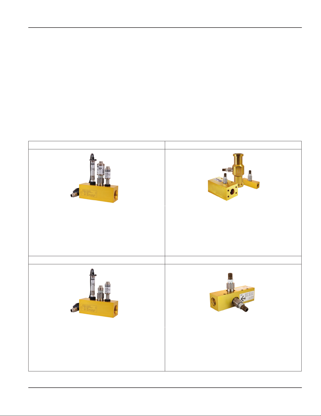
Flo-tech offers four different flow sensor models. Each of these models is available in a wide selection of flow ranges and
port sizes.
Activa Sensor Array Classic Flow Sensor
Features: Features:
• Four flow ranges
• Four port sizes
• Accuracy of ±1% reading @ 32 cSt
• Pressures up to 5800 psi (400 bar)
• Temperatures up to 300° F (150° C)
• 4…20 mA or 0…5V DC output for flow
• 4…20 mA output for pressure and temperature
Ultima Sensor Array Quad Flow Sensor
Features: Features:
• Four flow ranges
• Four port sizes
• Accuracy of ±1% full scale
• Pressures up to 5800 psi (400 bar)
• Temperatures up to 300° F (150° C)
• Frequency output for flow
• 4…20 mA output for pressure and temperature
• Eight flow ranges
• Eight port sizes
• Accuracy of ±1% full scale
• Pressures up to 6000 psi (414 bar)
• Temperatures up to 300° F (150° C)
• Frequency output for flow
• Four flow ranges
• Two port sizes
• Accuracy of ±1% full scale
• Pressures up to 6000 psi (414 bar)
• Temperatures up to 300° F (150° C)
• Frequency output for flow
Page 3 March 2019 SEN-UM-00987-EN-04
Page 4
Operating Principle
OPERATING PRINCIPLE
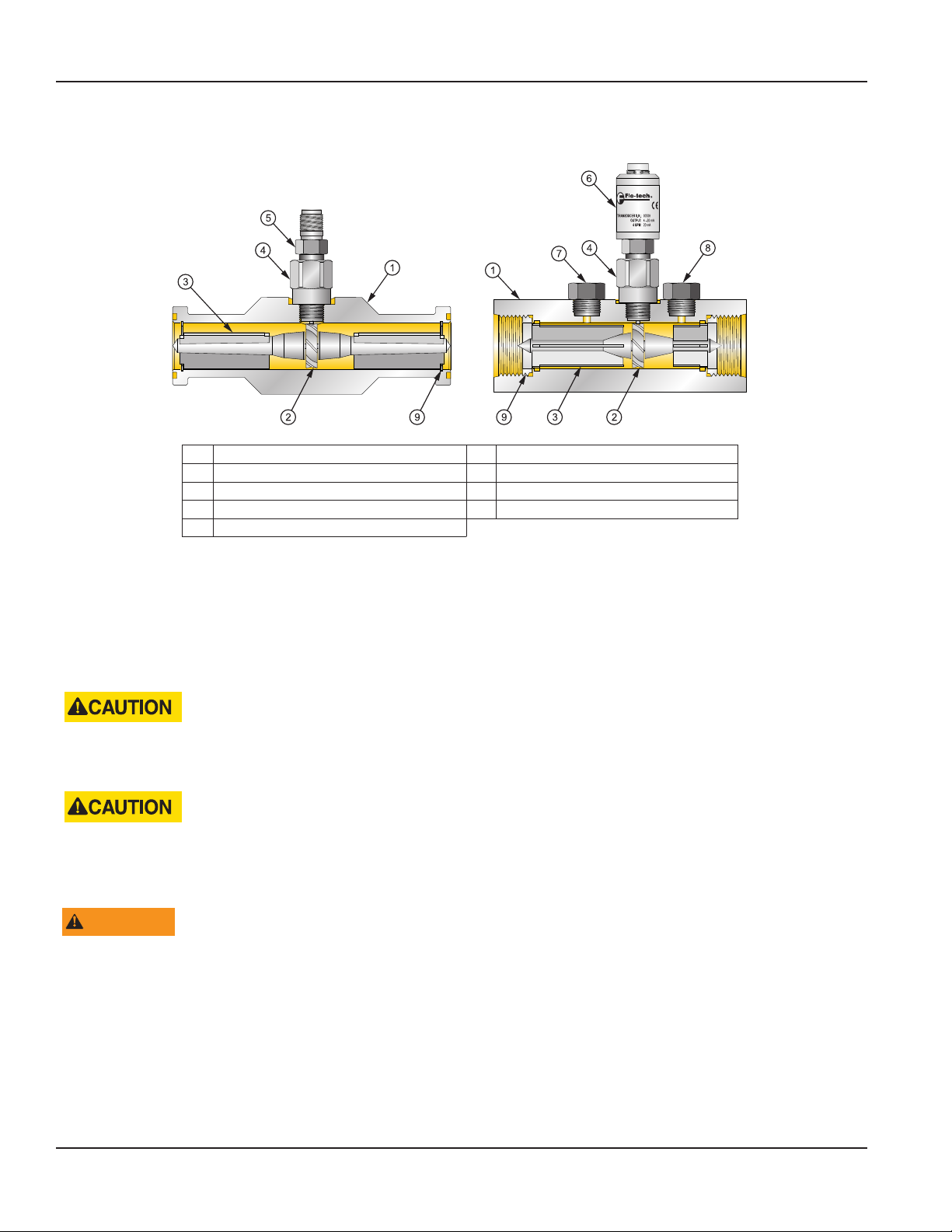
1 Housing 6 Signal Converter (analog output)
2 Turbine Rotor 7 Pressure Port Adapter
3 Rotor Supports 8 Temperature Port Adapter
4 Lock Nut 9 Retaining Rings
5 Magnetic Pickup (frequency output)
Turbine flow sensors measure the flow rate of hydraulic fluid and compatible liquids. As fluid flows through the sensor it turns
the turbine rotor, and as the turbine blades pass the magnetic pickup a frequency signal is generated. This frequency signal is
proportional to the flow rate and can be transmitted to Flo-tech’s digital displays or converted to an analog output. Optional
sensors allow measurement of pressure and temperature.
INSTALLATION
THIS PRODUCT SHOULD BE INSTALLED AND SERVICED BY TECHNICALLY QUALIFIED PERSONNEL TRAINED IN
MAINTAINING INDUSTRIAL CLASS FLOW INSTRUMENTATION AND PROCESSING EQUIPMENT.
READ INSTRUCTIONS THOROUGHLY BEFORE INSTALLING THE FLOW SENSOR. IF YOU HAVE ANY QUESTIONS
REGARDING PRODUCT INSTALLATION OR MAINTENANCE, CALL YOUR LOCAL SUPPLIER OR THE FACTORY FOR MORE
INFORMATION.
WARNING
DO NOT USE MALE PIPE THREADS (NPT) INTO SAE STRAIGHT THREAD PORTS. USING MALE PIPE THREADS (NPTF)
WITH A FLOW SENSOR POSSESSING SAE STRAIGHT THREAD O-RING PORTS WILL NOT CREATE A PROPER SEAL AND
IS POTENTIALLY DANGEROUS. PIPE THREADS INSERTED INTO AN SAE STRAIGHT THREAD PORT ONLY ALLOW THE
ENGAGEMENT OF ONE OR TWO THREADS. NO AMOUNT OF TIGHTENING OR THREAD SEAL WILL STOP THE LEAKING
OR MAKE THE INSTALLATION SAFE. FAILURE TO FOLLOW THESE INSTRUCTIONS COULD RESULT IN SERIOUS PERSONAL
INJURY OR DEATH AND/OR DAMAGE TO THE EQUIPMENT.
Page 4 March 2019SEN-UM-00987-EN-04
Page 5
Installation
Installation Recommendations
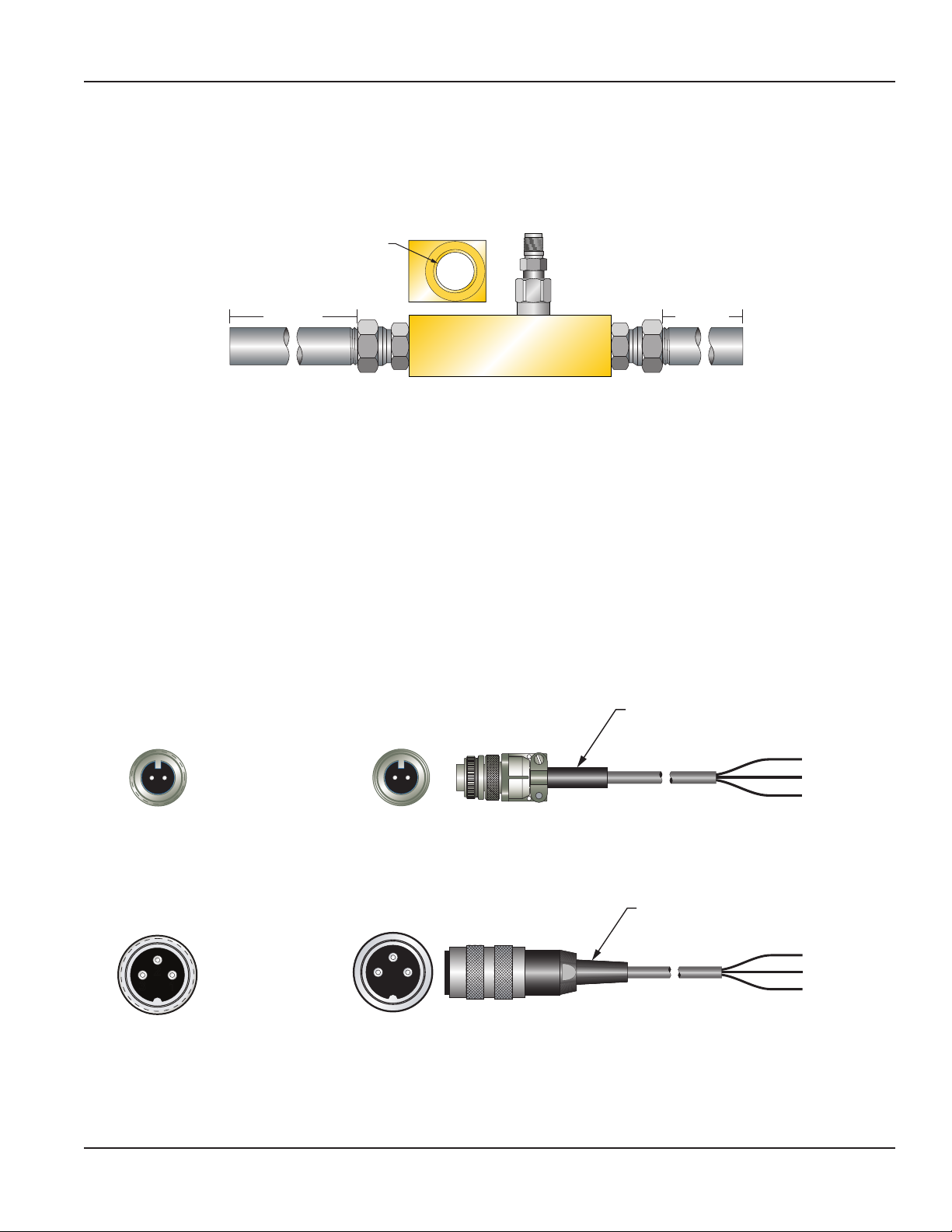
The in-line flow sensor is a simple device to install. However, the following measures are recommended for reliable,
trouble-free operation:
1. Provide at least 10 port diameters of upstream straight pipe with no obstructions to the ow sensor and at least 5
diameters of downstream pipe. The pipe should be of the same diameter as the nominal port size.
1" PORT
(25.4 mm)
END VIEW
10 PORT DIAMETERS
10" (254 mm)
IN
5 PORT DIAMETERS
5" (127 mm)
Example:
An FSC-1000 has a 1 in. (25.4 mm) port. The unobstructed upstream length should be at least 10 in. (254 mm) and the
downstream length should be at least 5 in. (127 mm).
2. Choose a position for the ow sensor that is not at the lowest level in the system. Placing the ow sensor at a higher
elevation in the system will avoid collection of debris, sediment and dirt in the ow sensor.
3. Use a lter. All applications should be ltered to at least 40 micron.
4. Do not install a ow sensor directly in-line with the outlet of a pump, as pressure pulsations can react with the turbine.
Install the sensor after another component, observing the 10 port diameter rule.
5. Do not adjust the magnetic pickup on the ow sensor. This is calibrated at the factory. Further adjustment will cause a
decrease in performance or damage to the sensor.
6. Do not exceed the working temperature range of –4…300° F (–20…150° C). Higher temperatures will damage the
magnetic pickup and lower temperatures will limit the rotation of the turbine.
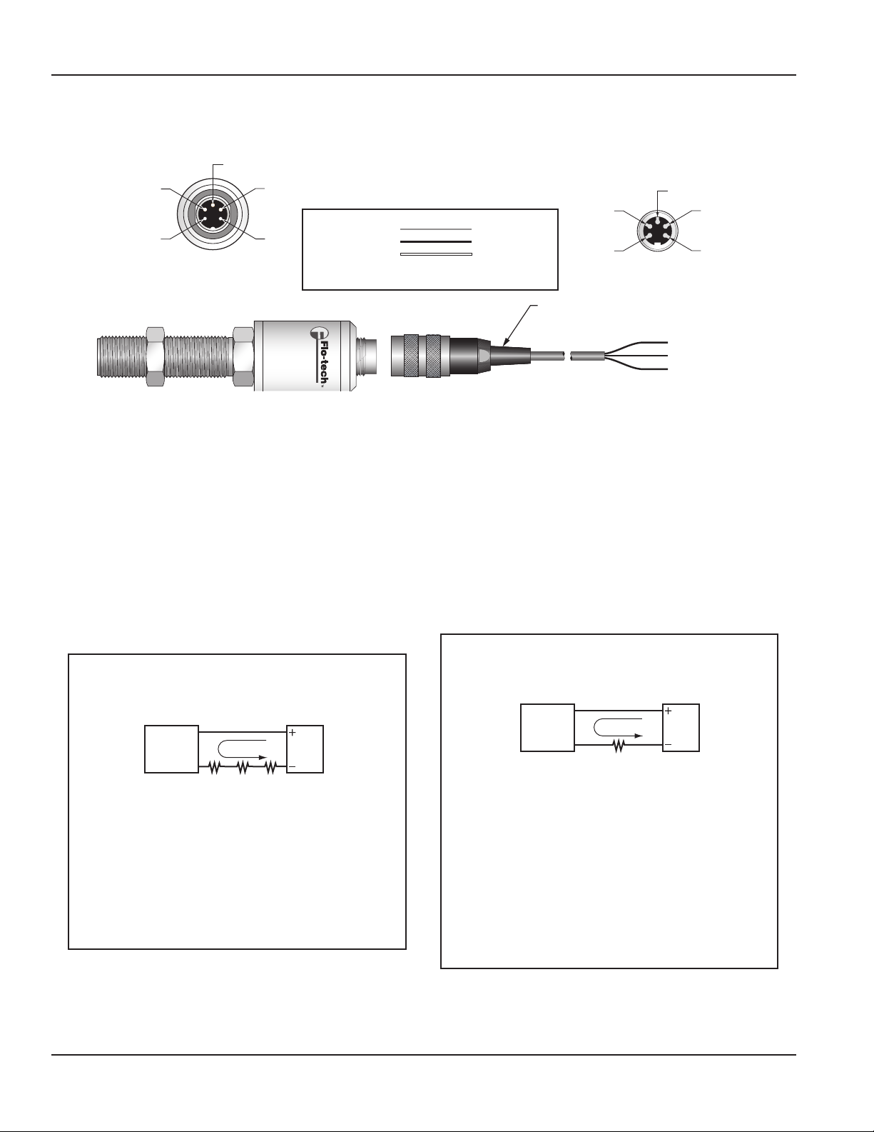
Electrical Connections for Standard Magnetic Pickup
Standard Magnetic Pickup with Frequency Output, 2-pin Connector
Cable Assembly
F2832-6 6 ft
F2832-15 15 ft
B
B (BLACK) –
A
A (RED)
+
B A
(BLACK) –
(RED)
+
(WHITE) N.C.
Magnetic Pickup
Male Connector
2
1
3
Magnetic Pickup
Male Connector
Top of
F2832 Cable
Standard Magnetic Pickup with Frequency Output, 3-pin Connector
1 (WHITE) N.C.
2 (BLACK) –
3 (RED) +
2
3
1
Top of
F6234 Cable
Cable Assembly
F6234-6 6 ft
F6234-15 15 ft
(BLACK) –
(RED)
+
(WHITE) N.C.
Page 5 March 2019 SEN-UM-00987-EN-04
Page 6
Installation
Electrical Connections for IFC (Intelligent Frequency Converter)
IFC with 4…20 mA Output (F to I), 5-pin Connector
3
4
5
F to I Converter
Male Connector
The 4…20 mA output can drive auxiliary devices (resistive loads) such as displays, recorders and computers, provided that the
voltage supplied by the power supply is adequate. Devices must be wired in series with the F to I converter and power supply.
The voltage drop across the load(s) and the 6V DC minimum needed to drive the F to I converter determine the minimum
voltage required from the power supply.
Determine the necessary voltage required to adequately drive the F to I converter and auxiliary device(s).
The F to I converter acts as a current controlling device keeping the current output the same even if the power supply voltage
fluctuates or the load resistance changes. The current varies only with respect to the flow rate from the turbine flow sensor, as
long as the voltage drop across the F to I converter is at least 6V DC.
The load(s) in the circuit will generally have some electrical resistance, 100 Ohms for this example. The 4…20 mA loop current
will produce a voltage drop across each load. The maximum voltage drop across a load(s) will exist when the loop current is
20 mA. The power supply must provide enough voltage for the load(s) plus the 6V DC minimum insertion loss of the
F to I converter.
2
1
+ 4…20 mA
– 4…20 mA
N.C.
N.C.
N.C.
PIN 1
PIN 2
PIN 3
PIN 4
PIN 5
RED
BLACK
WHITE
+ 4…20 mA (Sink)
– 4…20 mA (Source)
No Connection
Cable Assembly
F6557-6 6 ft
F6557-15 15 ft
2
1
3
4
5
Cable
Connector
(RED) + Loop
(BLACK) – Loop
(WHITE) N.C.
Sucient Power Supply Voltage
Example 1
F to I
Converter
150
Ohms
4…20 mA
100
Ohms50Ohms
Total Load Resistance = 300 Ohms
At 20 mA loop current, the voltage drop across the load(s)
is 6 volts:
300 Ohms × 20 mA = 6000 mV or 6 volts
Subtract 6 volts from the 24 volt source to determine that
18 volts is available to power the F to I converter. The 18
volts is within the specied 10…30 volt range and is
sucient to power the F to I converter.
Page 6 March 2019SEN-UM-00987-EN-04
24V DC
Power
Supply
At 20 mA loop current, the voltage drop across the load(s)
Subtract 20 volts from the 24 volt source to determine that
4 volts is available to power the F to I converter. The 4
volts is below the specied 10…30 volt range and is not
adequate to power the F to I converter. If for example, the
power supply voltage was 30 volts instead of 24 volts, the
voltage available to power the F to I converter would be 10
volts and within the specied range.
Insucient Power Supply Voltage
Example 2
F to I
Converter
4…20 mA
1000
Ohms
Total Load Resistance = 1000 Ohms
is 14 volts:
1000 Ohms × 20 mA = 20,000 mV or 20 volts
24V DC
Power
Supply
Page 7
Loop Load (Ohm's)
4
5
F to V Converter
Male Connector
1400
1200
1000
800
600
400
Operate in the
Shaded Region
200
10 12 14 16 18 20 22 24
Supply Voltage (VDC)
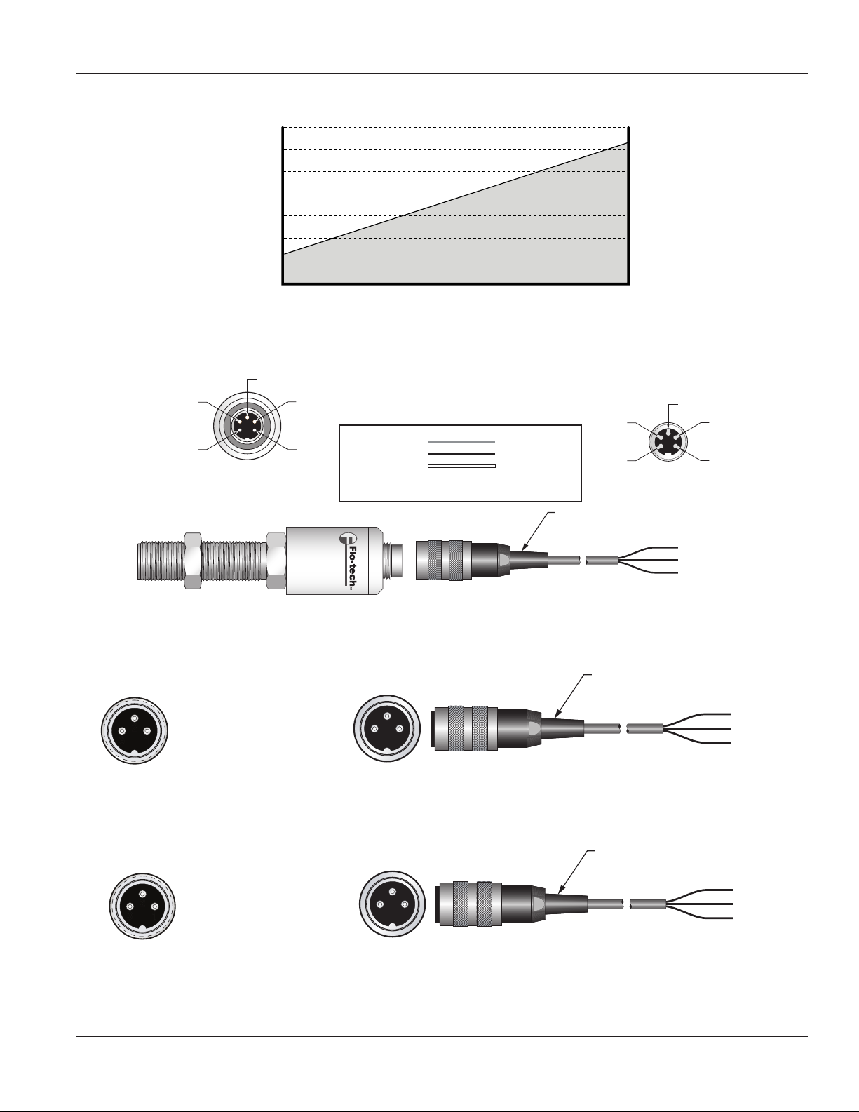
IFC with 0…5V DC Output (F to V), 5-pin Connector
3
2
10…26V DC
1
SIGNAL
GND
N.C.
N.C.
PIN 1
PIN 2
PIN 3
PIN 4
PIN 5
RED
BLACK
WHITE
10…26V DC
SIGNAL
0V
26
28 30
2
1
Installation
3
4
5
Cable
Connector
Cable Assembly
F6557-6 6 ft
F6557-15 15 ft
Electrical Connections for Optional Pressure and Temperature Sensors
Pressure Sensor, Optional, 3-pin Connector
2
1
3
Pressure Sensor
Male Connector
2
1
3
1 N/C (WHITE)
2 – Signal Output (BLACK)
3 + Voltage (RED)
Temperature Sensor, Optional – 3-pin Connector
1 Case Ground (WHITE)
2 – Signal Output (BLACK)
3 + Voltage (RED)
2
3
1
Top of
F6234 Cable
2
3
1
Cable Assembly
F6234-6 6 ft
F6234-15 15 ft
Cable Assembly
F6234-6 6 ft
F6234-15 15 ft
(RED) 10…26V DC
(BLACK) SIGNAL
(WHITE) 0V
(BLACK) –
(RED)
+
(WHITE) N.C.
(BLACK) –
(RED)
+
(WHITE) N.C.
Temperature Sensor
Male Connector
Top of
F6234 Cable
Page 7 March 2019 SEN-UM-00987-EN-04
Page 8

Operation
OPERATION
General
WARNING
DO NOT EXCEED ALLOWABLE PRESSURE RATINGS. PRESSURE IN EXCESS OF THE MAXIMUM ALLOWABLE RATINGS MAY
CAUSE THE TURBINE BODY TO FAIL. FAILURE TO FOLLOW THESE INSTRUCTIONS COULD RESULT IN SERIOUS PERSONAL
INJURY OR DEATH AND/OR DAMAGE TO THE EQUIPMENT.
1. Allow uids to warm to operating temperatures before critical measurements are taken.
2. Maintain a ooded condition in the ow sensor at all times. Air and turbulence will result in erroneous readings.
3. Do not exceed the working temperature range of –4…300° F (–20…150° C). Higher temperatures will damage the
magnetic pickup and lower temperatures will limit the rotation of the turbine.
Flow Sensors with IFC Option
As soon as power is applied, the IFC will begin to output an analog value representative of the measured frequency from the
turbine meter. See the wiring diagram that corresponds to the IFC being used.
MAINTENANCE
WARNING
ALWAYS DISCONNECT THE PRIMARY POWER SOURCE BEFORE INSPECTION OR SERVICE. FAILURE TO FOLLOW THESE
INSTRUCTIONS COULD RESULT IN SERIOUS PERSONAL INJURY OR DEATH AND/OR DAMAGE TO THE EQUIPMENT.
1. A schedule for maintenance checks should be determined based on environmental conditions and frequency of use.
Inspect the sensors at least once a year.
2. Perform visual, electrical and mechanical checks on all components.
a. Visually check for undue heating evidenced by discoloration of wires or other components, damaged or worn parts, or
excessive corrosion of the device.
b. Electrically check to make sure that all connections are clean and tight and that the device is operating properly.
Page 8 March 2019SEN-UM-00987-EN-04
Page 9

TROUBLESHOOTING
Issue Possible Cause Remedy
Troubleshooting
Sensor indicates higher
than actual flow rate
Sensor indicates lower
than actual flow rate
Erratic indications on
readout
Readout shows flow
when pumps are not
running
No flow indication at any
flow rate
Erratic indications at
low flows, but good
indications at high flows
System works except
readings are lower than
expected
No current output
Analog output reads a
constant reading all the
time
Analog output is not
stable
• Cavitation
• Debris on straightening section
• Build-up of foreign material on sensor bore
• Gas in liquid
• Debris on turbine
• Worn bearing
• Any of the above
• Ground loop problem
• Turbulence in fluid stream
• Mechanical vibration or pump dither
causes turbine to oscillate even though
there is no flow
• Foreign material stopping turbine rotation
• Damaged turbine and/or bearing
• Magnetic pickup stopping turbine rotation
• Magnetic pickup shorted or open
• Foreign material wrapped around turbine • Clean sensor and add filter
• Flow is being bypassed
• System has a leak
• Low or missing supply voltage
• Broken / disconnected wires
• Incorrect wiring polarity
• Electrical noise in vicinity
• Damaged electronics
• Electrical noise in vicinity
• Entrained gas in liquid
• Damaged meter rotor
• Foreign matter lodged in turbine
• Increase back pressure
• Clean sensor
• Clean sensor
• Install gas eliminator ahead of sensor
• Clean sensor and add filter
• Have sensor serviced and add filter
• Any of the above
• Be sure only one system ground is present.
Reroute cables away from electrical noise
• Redo plumbing per instructions
• Isolate flow sensor
• Clean sensor and add filter
• Have sensor or magnetic pickup replaced
• Repair or replace faulty valves
• Find and repair any system leaks
• Check polarity of the current loop
connections for proper orientation
• Make sure receiving device is configured to
provide loop current
• Make sure there is flow in the system
• Verify that the rotor inside the turbine
meter turns freely
• Check shield
• Remove noise producing device
• External noise is being picked up by the
sensor. Keep all AC wires separate from DC
wires.
• Check for radio antenna in close proximity.
This usually indicates a weak signal.
• Clean meter
• Recalibrate meter
Page 9 March 2019 SEN-UM-00987-EN-04
Page 10
Dimensions
B
A
A
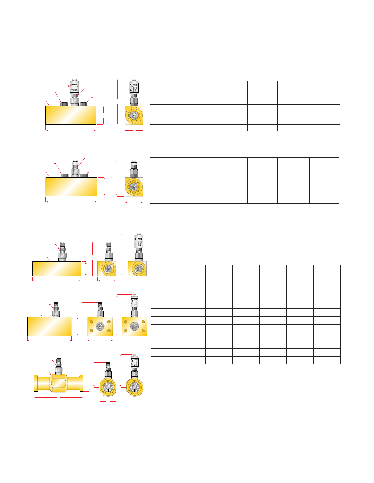
DIMENSIONS
Activa Series
Signal Converter
Pressure Port
Adapter
Housing
Ultima Series
Pressure Port
Adapter
Housing
Classic Series
FSC
Magnetic Pickup
Housing
Magnetic Pickup
Temperature Port
Adapter
B A
Magnetic Pickup
Temperature Port
Adapter
B A
D
D
C
D
C
E
Weight
lbs
(kg)
Series
A
in. (mm)B in. (mm)C in. (mm)D in. (mm)
F6202 / F6222 1.23 (31.2) 4.72 (120.0) 1.47 (37.3) 5.74 (145.6) 1.60 (0.73)
F6204 / F6224 1.48 (37.6) 5.08 (129.0) 1.80 (45.7) 6.04 (153.0) 1.90 (0.86)
F6206 / F6226 1.98 (50.3) 5.87 (149.0) 2.20 (56.0) 6.50 (164.0) 2.80 (1.27)
F6208 / F6228 2.46 (62.5) 6.81 (173.0) 2.48 (63.0) 6.74 (171.0) 4.20 (1.91)
Weight
lbs
(kg)
Series
A
in. (mm)Bin. (mm)Cin. (mm)Din. (mm)
F6202 / F6222 1.23 (31.2) 4.72 (120.0) 1.47 (37.3) 5.74 (145.6) 1.60 (0.73)
F6204 / F6224 1.48 (37.6) 5.08 (129.0) 1.80 (45.7) 6.04 (153.0) 1.90 (0.86)
F6206 / F6226 1.98 (50.3) 5.87 (149.0) 2.20 (56.0) 6.50 (164.0) 2.80 (1.27)
F6208 / F6228 2.46 (62.5) 6.81 (173.0) 2.48 (63.0) 6.74 (171.0) 4.20 (1.91)
FSB
Magnetic Pickup
Housing
FSD
Magnetic Pickup
Housing
C
Series
A
in. (mm)B in. (mm)C in. (mm)
D
W/Mag
in. (mm)
E
W/IFC
in. (mm)
Weight
lbs
(kg)
FSC-375 1.25 (32) 5.00 (127) 1.50 (38) 3.91 (99) 5.48 (139) 1.25 (0.57)
FSC-500 2.00 (51) 6.50 (165) 2.00 (51) 4.16 (106) 5.84 (148) 2.75 (1.25)
FSC-750 2.00 (51) 6.50 (165) 2.00 (51) 4.25 (108) 5.93 (151) 2.87 (1.30)
D
C
B
E
A
FSC-1000 2.50 (64) 6.50 (165) 2.00 (51) 4.34 (110) 5.97 (152) 3.25 (1.48)
FSC-1005 2.50 (64) 6.50 (165) 2.00 (51) 4.34 (110) 5.97 (152) 3.25 (1.48)
FSB-1250 4.00 (102) 7.00 (178) 3.00 (76) 4.94 (126) 6.43 (165) 7.75 (3.52)
FSB-1500 4.00 (102) 7.00 (178) 3.00 (76) 5.10 (130) 6.59 (167) 7.40 (3.36)
FSD-1250 2.12 (54) 7.50 (190) 2.125 (54) 4.50 (114) 5.17 (131) 6.12 (2.78)
FSD-1500 2.50 (64) 7.50 (190) 2.500 (64) 4.85 (123) 5.34 (135) 6.75 (3.06)
FSD-2000 3.12 (79) 8.25 (209) 3.125 (79) 5.39 (137) 5.45 (138) 8.55 (3.88)
D
C
B
E
Page 10 March 2019SEN-UM-00987-EN-04
Page 11
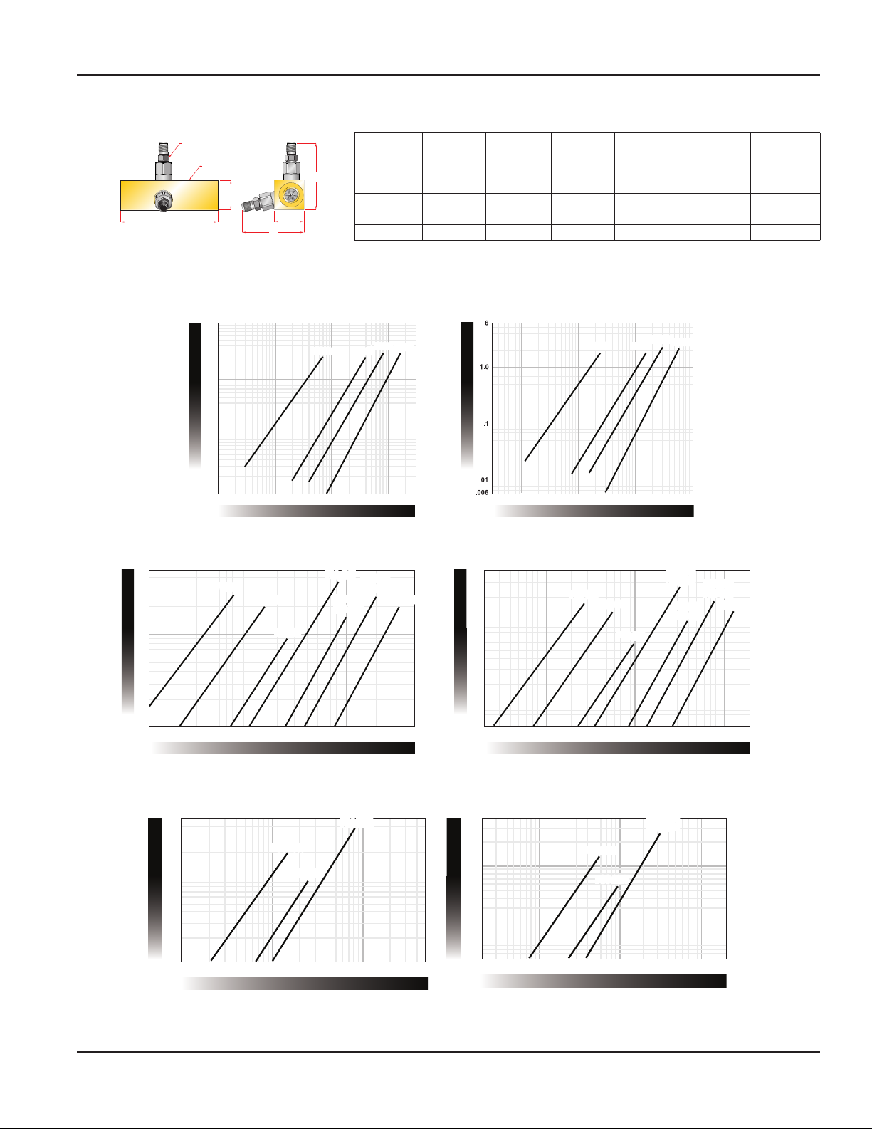
Quad Series
PRESSURE DROP BAR
PRESSURE DROP PSI
PRESSURE DROP PSI
PRESSURE DROP BAR
FSC-1000
PRESSURE DROP PSI
PRESSURE DROP BAR
Flow vs. Pressure Drop Charts
Magnetic Pickup (2)
Housing
C
B A
E
D
Series
in. (mm)B in. (mm)C in. (mm)
FSC-2005 2.00 (51) 6.50 (165) 2.00 (51) 4.16 (106) 4.05 (102) 2.75 (1.25)
FSC-2075 2.00 (51) 6.50 (165) 2.00 (51) 4.25 (108) 4.05 (102) 2.87 (1.30)
FSC-2100 2.50 (64) 6.50 (165) 2.00 (51) 4.34 (110) 4.59 (117) 3.25 (1.47)
FSC-2150 2.50 (64) 6.50 (165) 2.00 (51) 4.34 (110) 4.59 (117) 7.75 (3.52)
FLOW VS. PRESSURE DROP CHARTS
Activa and Ultima Series
100
F6206
F6204
FSB-1500
FSD-1500
F6208
FSD-2000
Classic Series
50
10
F6202
10
1
.1
.1 1 10 100 300
FSC-375
FSC-500
FSC-750
FLOW GPM
FSC-1005
FSB-1250
FSD-1005
A
F6222
.1 10 100 1000
4
1
FLOW LPM
FSC-375
FSC-500
D
W/Mag
in. (mm)
F6224
FSC-750
F6226
FSC-1000
FSC-1005
W/Mag
in. (mm)
F6228
FSB-1500
FSD-1500
FSB-1250
FSD-1005
E
FSD-2000
Weight
lbs (kg)
.1
.1 10 100 500 10 100 1000 2000
Quad Series
FLOW GPM FLOW LPM
50
FSC-2005
10
1
1 10 100 500
FSC-2075
FSC-2100
FSC-2150
FLOW GPM
0.07
0.07
0.1
4
FSC-2005
1
FSC-2075
0.1
10 100 1000 2000
FSC-2100
FSC-2150
FLOW LPM
Page 11 March 2019 SEN-UM-00987-EN-04
Page 12
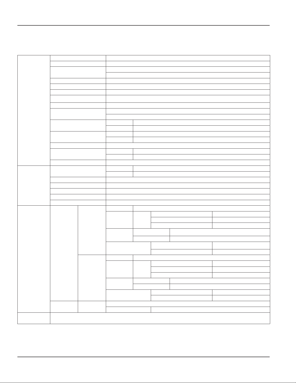
Specications
SPECIFICATIONS
Activa and Ultima Sensor Arrays
Housing 6013-T651 Anodized aluminum
Turbine rotor T416 Stainless steel
Rotor supports
Rotor shaft T303 Stainless steel
Ball bearings 440 C Stainless steel
Hub cones 6061-T6 Aluminum alloy
Retaining rings 6061-T6 Aluminum alloy
Adapters/plugs 6061-T6 Anodized aluminum
Material
Performance
Electrical
Calibration
Seals
Magnetic pickup
IFC (Intelligent Frequency
Converter) Activa only
Temperature probe 12L14 Steel, electroless nickel finish
Pressure Sensor
Ports SAE Straight thread O-ring boss, female, J1926/1; ISO1179 (BSPP)
Flow accuracy
Repeatability ±0.2%
Pressure rating 5800 psi (400 bar) maximum, 5000 psi (345 bar) maximum for 1-1/4 in. models
Turbine response ≤200 ms
Fluid temperature –4…300° F (–20…150° C)
Ambient temperature –4…131° F (–20…55° C)
4…20 mA
Activa
0…5V DC
Ultima
Flow sensors are calibrated with 0.876 specific gravity, 140 SUS (32 cSt) hydraulic oil. Standard calibration is
done using 3-points and is traceable to NIST, ISO 9001/ANSI Z540-1 & MIL-STD 45662A.
Magnetic
Pickup
6061-T6 Aluminum
C360 Brass for 1/4 in. models
Buna N standard
Viton® and EPR optional
Body T303 Stainless Steel
Nut T303 Stainless Steel
Body 6061-T6 Aluminum, nickel plate
Connector Brass, nickel plate
Case 300 Series stainless steel
Diaphragm 17-4 PH stainless steel
Activa ±1% of reading @ 32 cSt
Ultima ±1% of full scale
Power Loop-powered, 6V insertion loss max, 10…30V DC supply
Inputs
Analog out
Environmental
Power 10…26V DC
Inputs
Analog out
Environmental
Self-generating alternating pulse; 100 mV RMS (100 Hz) minimum.
F6202 & F6222 only 10 mV RMS (200Hz) minimum
Mag
pickup
Resolution 1:4000
Temp Drift 50 ppm/° C max
Mag
pickup
Resolution 1:4000
Temp. drift 50 ppm/°C max
Frequency 0…3500 Hz
Trigger sensitivity 30 mV p-p
Frequency measure accuracy ±1%
Ambient temp. –22…158° F (–30…70° C)
Humidity 0…90% non-condensing
Frequency 0…3500 Hz
Trigger sensitivity 30 mV p-p
Frequency measure accuracy ±1%
Ambient temp. –22…158° F (–30…70° C)
Humidity 0…90% non-condensing
Page 12 March 2019SEN-UM-00987-EN-04
Page 13
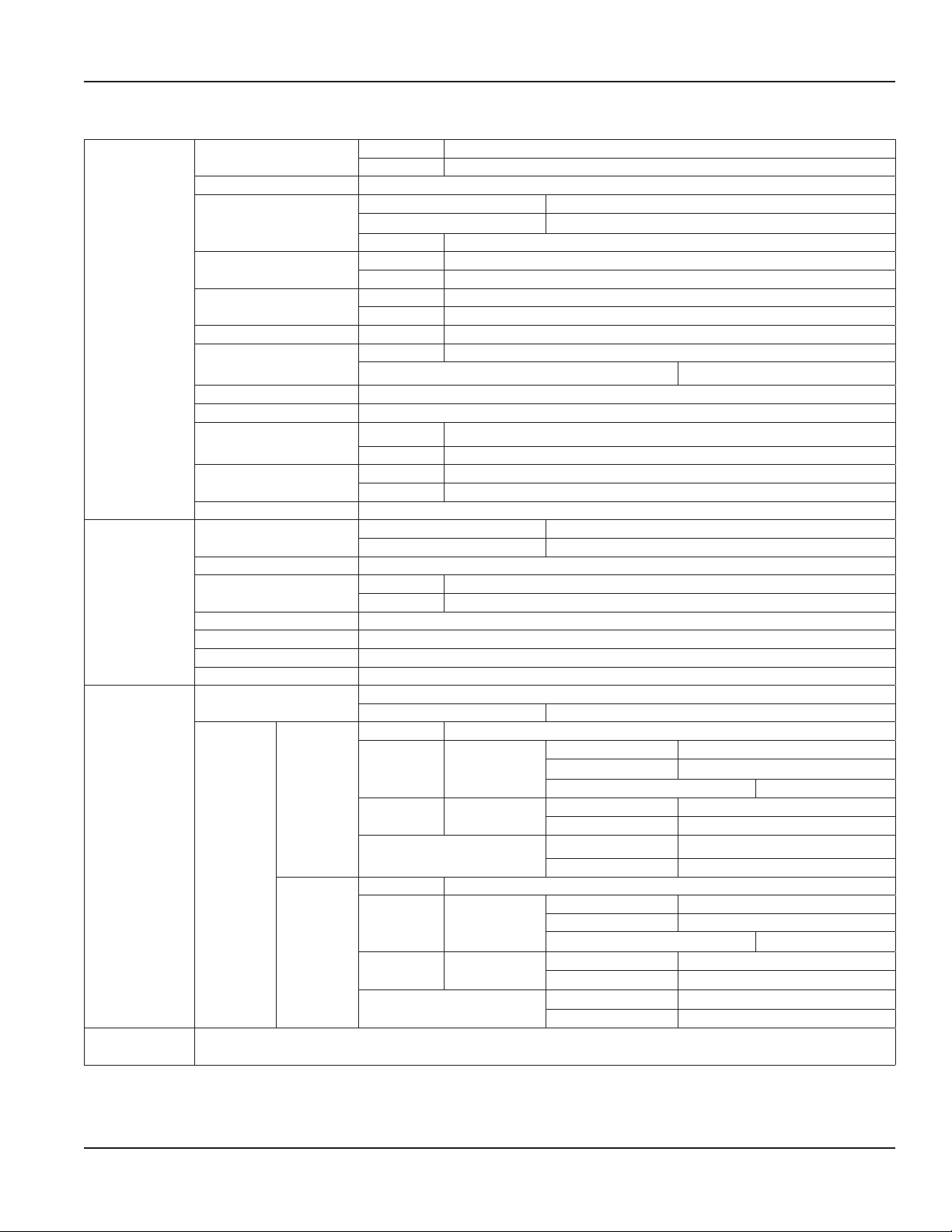
Classic Flow Sensor
Specications
Materials
Performance
Electrical
Calibration
Housing
Turbine rotor T416 Stainless steel
Rotor supports
Rotor shaft
Bearings
Hub cones FSC, FSB 6061-T6 Aluminum alloy
Retaining rings
Adapters/plugs 6061-T6 Anodized aluminum
Seals Buna N standard, Viton® and EPR optional
Magnetic pickup
IFC (Intelligent
Frequency Converter):
Ports: SAE Straight thread O-ring boss, female, J1926/1; Code 61 and Code 62: SAE J518
Flow accuracy
Repeatability ±0.2%
Pressure rating
Pressure drop See “Flow vs. Pressure Drop Charts” on page 11
Turbine response ≤200 ms
Fluid temperature –4…300° F (–20…150° C)
Ambient temperature –4…131° F (–20…55° C)
Magnetic Pickup
4…20 mA
IFC
Converter
0…5V DC
Flow sensors are calibrated with 0.876 specific gravity, 140 SUS (32 cSt) hydraulic oil. Standard calibration is
done using 3-points and is traceable to NIST, ISO 9001/ANSI Z540-1 & MIL-STD 45662A
FSC, FSB 6013-T651 Anodized aluminum
FSD Stressproof® steel, zinc plated
FSC-375, 500, 750 C360 Brass
FSC-1000, 1005 6061-T6 Aluminum
FSD Tungsten carbide
FSC, FSB T303 Stainless steel
FSD Tungsten carbide
FSC, FSB 440 C Stainless steel ball bearings
FSD Tungsten carbide
FSC T303 Stainless steel
FSC-500, 750, 1000, 1005; FSB; FSD Steel, zinc plate
Body T303 Stainless Steel
Nut T303 Stainless Steel
Body 6061-T6 Aluminum, nickel plate
Connector Brass, nickel plate
Standard magnetic pickup ±1% of full scale
IFC converter option ±1% of reading @ 32 cSt
FSC, FSB 5000 psi (345 bar) maximum,
FSD 6000 psi (414 bar) maximum
Self-generating alternating pulse; 100 mV RMS (100 Hz) minimum.
FSC-375 only 10 mV RMS (200 Hz) minimum
Power Loop-powered, 6V insertion loss max 10…30V DC supply
Frequency 0…3500 Hz
Inputs Mag pickup
Analog out
Environmental
Power 10…26V DC
Inputs Mag pickup
Analog out 0…5V DC
Environmental
4…20 mA
current loop
Trigger sensitivity 30 mV p-p
Frequency measure accuracy ±1%
Resolution 1:4000
Temp. drift 50 ppm/°C max
Ambient temp. –22…158° F (–30…70° C)
Humidity 0…90% non-condensing
Frequency 0…3500 Hz
Trigger sensitivity 30 mV p-p
Frequency measure accuracy ±1%
Resolution 1:4000
Temp drift. 50 ppm/°C max
Ambient temp –22…158° F (–30…70° C)
Humidity 0…90% non-condensing
Page 13 March 2019 SEN-UM-00987-EN-04
Page 14
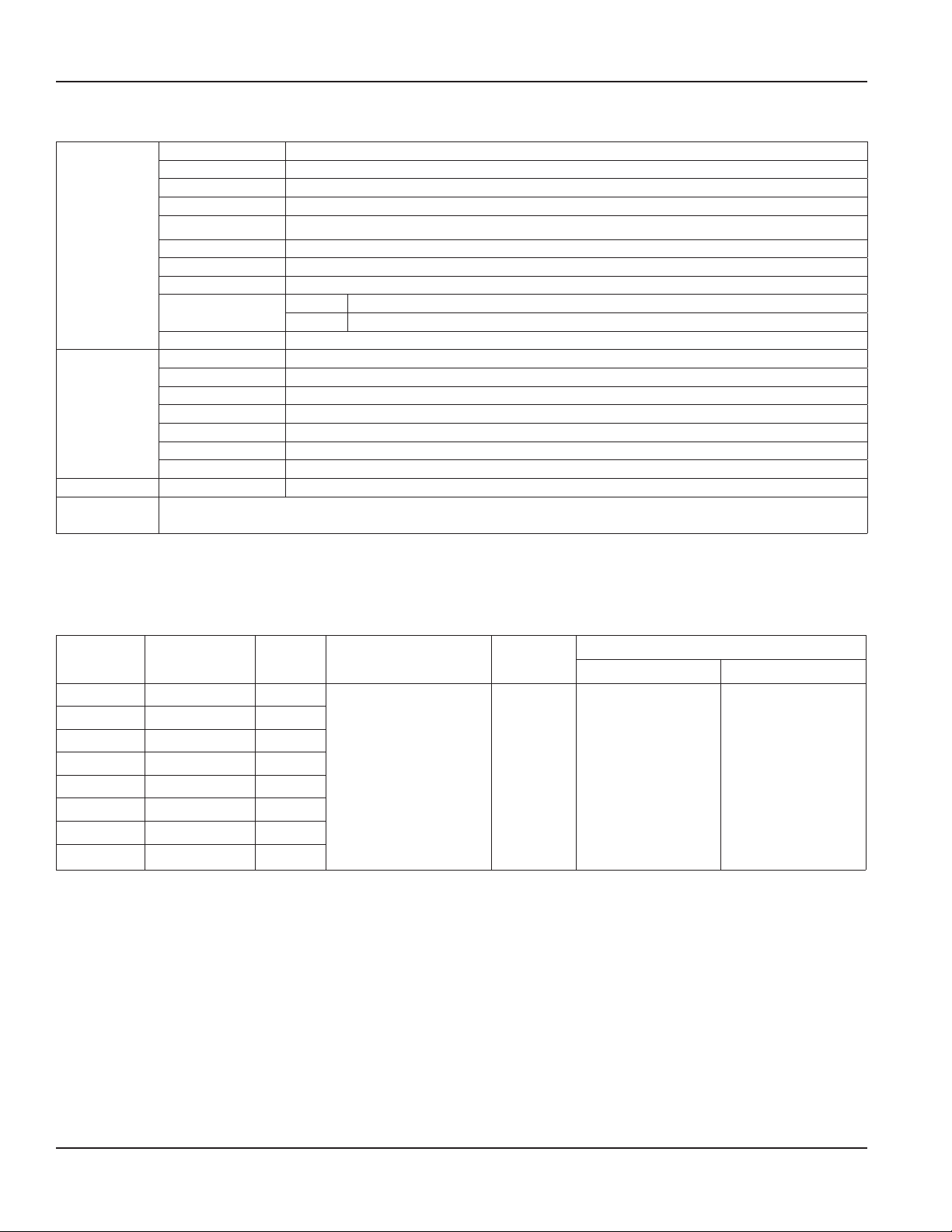
Model Numbers
Quad Flow Sensors
Housing 6013-T651 Anodized aluminum
Turbine rotor T416 Stainless steel
Rotor supports 6061-T6 Aluminum
Rotor shaft T303 Stainless steel
Bearings 440 C Stainless steel ball bearings
Material
Performance
Electrical Magnetic Pickup Self-generating alternating pulse; 100 mV RMS (100 Hz) minimum
Calibration
Hub cones 6061-T6 Aluminum alloy
Retaining rings Steel, zinc plate
Seals Buna N standard, Viton® and EPR optional
Magnetic pickup
Body T303 Stainless Steel
Nut T303 Stainless Steel
Ports SAE Straight thread O-ring boss, female, J1926/1
Flow accuracy ±1% of full scale
Repeatability ±0.2%
Pressure rating 5000 psi (345 bar) maximum
Pressure drop See “Flow vs. Pressure Drop Charts” on page 11
Turbine response ≤200 ms
Fluid temp. –4…300° F (–20…150° C)
Ambient temp. –4…131° F (–20…55° C)
Flow sensors are calibrated with 0.876 specific gravity, 140 SUS (32 cSt) hydraulic oil. Standard calibration is
done using 3-points and is traceable to NIST, ISO 9001/ANSI Z540-1 & MIL-STD 45662A.
MODEL NUMBERS
Activa and Ultima Flow Sensors
Nominal
Port Size
SAE 8 0.4…7 gpm F6202
SAE 12 2…40 gpm F6204
SAE 16 4…80 gpm F6206
SAE 20 8…160 gpm F6208
G 1/4 1.5…26 lpm F6222
G 3/4 7.5…151 lpm F6224
G 1 15…302 lpm F6226
G 1-1/2 30…605 lpm F6228
* Not available with Models F6208 or F6228
Example
F6204-AIB-T6 =
• SAE 12 ports, 2…40 gpm flow range
• Buna N seals, Temperature sensor
• 6000 psi (414 bar) pressure sensor
Flow Rate Model
IFC
Converter
or Mag Pickup
Activa Models:
AI 4…20 mA Out
AV 0…5V DC Out
Ultima Models:
F Frequency Out
Seals
B Buna N
V Viton
E EPR
Temperature Pressure
T with Sensor
N 1/4 NPT(F)
Plugged
S SAE 2 Plugged
G G 1/4 Plugged
D SAE 4 Plugged
Sensor Ports
F6208-FV-TN =
• SAE 20 ports, 8…160 gpm flow range
• Viton seals, Temperature sensor
• 1/4 NPT (F) plugged pressure port
1 1000 psi
3 3000 psi
5 5000 psi
6 6000 psi *
N 1/4 NPT(F)
Plugged
S SAE 2 Plugged
F G 1/4 Plugged
Page 14 March 2019SEN-UM-00987-EN-04
Page 15

Classic Flow Sensors
Model Numbers
Nominal
Port Size
SAE 8 0.4…7 gpm FSC-375 F2945-ASCM F2945-ASCI F2945-ASCV
SAE 12 1…15 gpm FSC-500 F2082-ASCM F2082-ASCI F2082-ASCV
SAE 12 2…25 gpm FSC-750 F2083-ASCM F2083-ASCI F2083-ASCV
SAE 16 3…60 gpm FSC-1000 F2084-ASCM F2084-ASCI F2084-ASCV
SAE 16 4…85 gpm FSC-1005 F2084-ASCM8 F2084-ASCI8 F2084-ASCV8
SAE 20, Code 61 5…100 gpm FSB-1250 F2085-ASBM F2085-ASBI F2085-ASBV
SAE 24, Code 61 7…200 gpm FSB-1500 F2086-ASBM F2086-ASBI F2086-ASBV
SAE 20, Code 62 5…100 gpm FSD-1250 F2085-SCDM F2085-SCDI F2085-SCDV
SAE 24, Code 62 7…200 gpm FSD-1500 F2086-SDCM F2086-SCDI F2086-SCDV
SAE 32, Code 62 10…350 gpm FSD-2000 F2998-SCDM F2998-SCDI F2998-SCDV
Flow Rate Series
Model
with Frequency Out
Model
with 4…20 mA Out
Model
with 0…5V DC Out
Quad Flow Sensors
Nominal
Port Size
SAE 12 1…15 gpm FSC-2005 F2082-ASCQ4
SAE 12 2…25 gpm FSC-2075 F2083-ASCQ4
SAE 16 3…60 gpm FSC-2100 F2084-ASCQ4
SAE 16 4…85 gpm FSC-2150 F2085-ASCQ4
Flow Rate Series Model
Page 15 March 2019 SEN-UM-00987-EN-04
Page 16

Turbine Flow Sensors, Activa, Ultima, Classic and Quad
Control. Manage. Optimize.
FLO-TECH is a registered trademarks of Badger Meter, Inc. Other trademarks appearing in this document are the property of their respective entities. Due to continuous research,
product improvements and enhancements, Badger Meter reserves the right to change product or system specications without notice, except to the extent an outstanding
contractual obligation exists. © 2019 Badger Meter, Inc. All rights reserved.
www.badgermeter.com
The Americas | Badger Meter | 4545 West Brown Deer Rd | PO Box 245036 | Milwaukee, WI 53224-9536 | 800-876-3837 | 414-355-0400
México | Badger Meter de las Americas, S.A. de C.V. | Pedro Luis Ogazón N°32 | Esq. Angelina N°24 | Colonia Guadalupe Inn | CP 01050 | México, DF | México | +52-55-5662-0882
Europe, Eastern Europe Branch Oce (for Poland, Latvia, Lithuania, Estonia, Ukraine, Belarus) | Badger Meter Europe | ul. Korfantego 6 | 44-193 Knurów | Poland | +48-32-236-8787
Europe, Middle East and Africa | Badger Meter Europa GmbH | Nurtinger Str 76 | 72639 Neuen | Germany | +49-7025-9208-0
Europe, Middle East Branch Oce | Badger Meter Europe | PO Box 341442 | Dubai Silicon Oasis, Head Quarter Building, Wing C, Oce #C209 | Dubai / UAE | +971-4-371 2503
Slovakia | Badger Meter Slovakia s.r.o. | Racianska 109/B | 831 02 Bratislava, Slovakia | +421-2-44 63 83 01
Asia Pacic | Badger Meter | 80 Marine Parade Rd | 19-07 Parkway Parade | Singapore 449269 | +65-63464836
Switzerland | Badger Meter Swiss AG | Mittelholzerstrasse 8 | 3006 Bern | Switzerland | +41-31-932 01 11 Legacy Document Number: 05-TUR-UM-00194
 Loading...