

Page 1
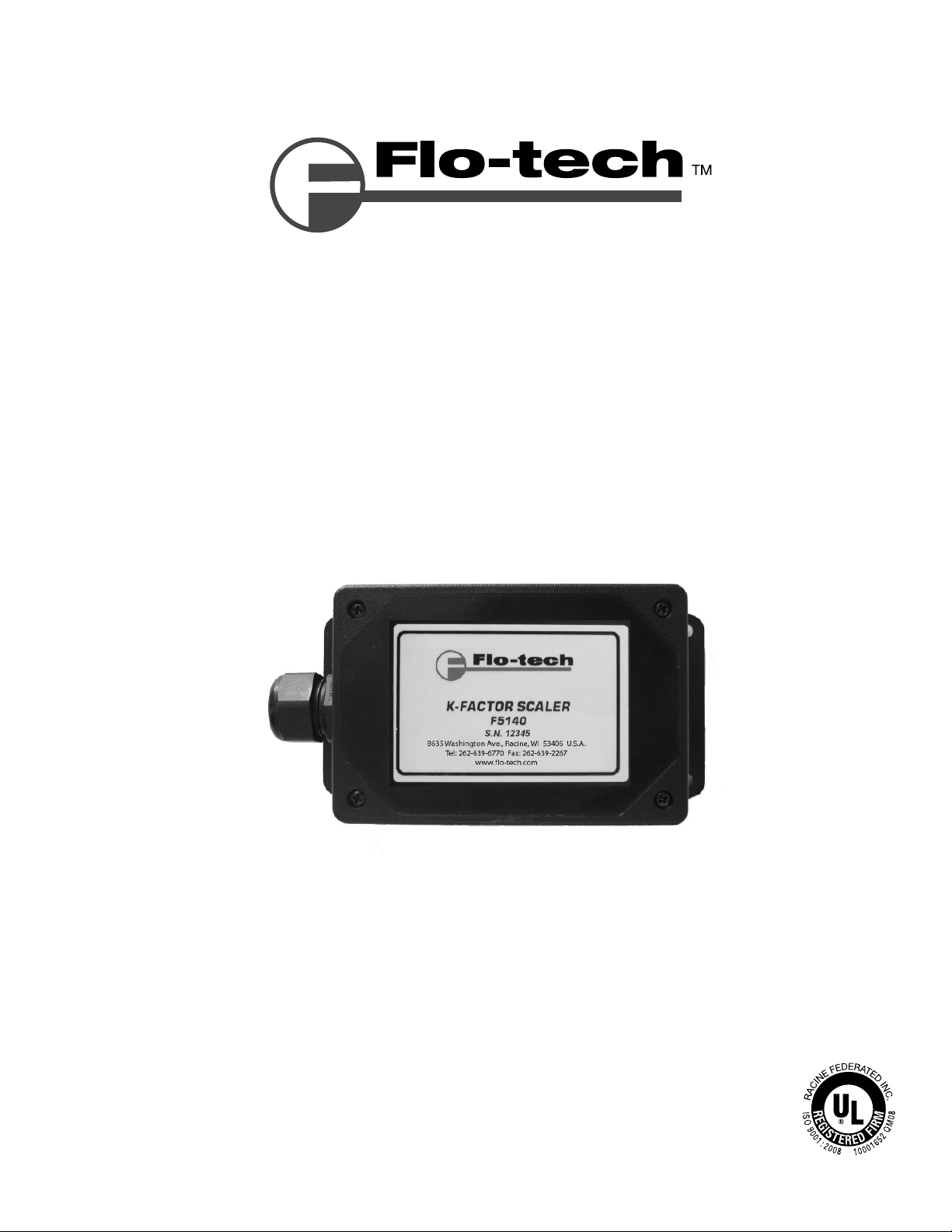
K-Factor Scaler F5140
and
Programming Kit F5141
Installation & Operating Instructions
8635 Washington Avenue Racine, WI 53406 USA
Tel: 800-433-5263 or 262-639-6770
Fax: 800-245-3569 or 262-639-2267
E-Mail: [email protected]
www. o-tech.com
Page 2

K-Factor Scaler
Installation & Operating Instructions
TABLE OF CONTENTS
Introduction ...................................................................................................................................................................................3
Operating Principle .....................................................................................................................................................................3
Speci cations .................................................................................................................................................................................3
Installation ......................................................................................................................................................................................4
Enclosure Mounting .........................................................................................................................................................4
Power ..........................................................................................................................................................................................4
Turbine Meter .........................................................................................................................................................................4
Pulse Output ...........................................................................................................................................................................4
Start-up and Con guration Using Optional Programming Software Kit F5141 ........................................... 5
Software ................................................................................................................................................................................5
Setting the K-factor .............................................................................................................................................................6
Setting the output pulse width......................................................................................................................................6
Setting the output level to normally high or normally low ............................................................................. 6
Setting the output pulse to use the internal or external pull-up resistor .................................................6
Return Goods Authorization ..................................................................................................................................................7
Waste Electrical and Electronic Equipment (WEEE) Directive ................................................................................ 7
Statement of Warranty .............................................................................................................................................................. 8
Page 2 Form #FLIT 555 11/10
Page 3

K-Factor Scaler
Installation & Operating Instructions
INTRODUCTION
The Flo-tech K-Factor Scaler is a eld adjustable frequency divider, which interfaces the output signal from a turbine meter with
a magnetic pick-up to the input of a PLC, RTU, CPU data acquisition card, or similar totalizer device. The adjustable frequency
divisor, referred to as the K-factor, allows the pulses being sent from a turbine meter to be divided into a recognizable unit that
an end device, such as a PLC can count and display.
OPERATING PRINCIPLE
Fluid moving though a turbine ow meter causes the rotor to rotate in relation to the ow rate. The rotation of the rotor blades
cuts through the magnetic eld generated by the magnetic pick-up which in turn generates a frequency output signal that is
directly proportional to the speed of the rotor.
The signal produced is received by the K-Factor Scaler input ampli er, which has an input sensitivity of 30 mV p-p to 30 V p-p.
The signal is then sent to an onboard microcontroller, which acts as a divisor with a range of 1 to 999,999,999. The divisor
(K-factor) is user adjustable through the optional programming software kit. The microcontroller handles the dividing process
by counting the input pulses and comparing it to the programmed K-factor value. Once the count equals this value, an output
pulse occurs for a selectable time period and the counting process starts over.
In addition, if the K-factor is set to 1, the K-Factor Scaler can be used as a pre-ampli er where the frequency from a low-level
turbine meter is proportional to the logic level frequency output needed by a PLC or CPU data acquisition card. This option
allows the end device to control the dividing process of the turbine meter output to a recognizable ow rate.
SPECIFICATIONS
External Power:
Input Voltage; 8.5 to 30 Vdc (Diode protected)
Maximum Current draw; 18 mA (using internal resistor @ 30 Vdc input)
Environmental:
Operating Temperature; -22 ˚F (-30 ˚C) to +158 ˚F (+70 ˚C)
Inputs:
Magnetic Pick-up Input
Frequency Range; 0 to 4000 Hz
Trigger Sensitivity; 30 mV p-p to 30 V p-p
Output Signal:
Max. Voltage; 30 Vdc
Max Power; 0.25 W
Pulse Type (using internal pull-up resistor);
VH = Power Input Voltage – 0.7 Vdc
VL = Less then 0.4 V @ max input power
Pulse Type (using external pull-up resistor);
VH = Input Voltage to external pull-up resistor
VL = [VH /(selected resistor value + 47)] × 47
Pulse Length; 150μs, 1ms, 25ms, 100ms, 500ms, 1s, or Auto mode selectable.
Output Options:
Jumper Con gurations
Internal Pull-up; 3.6K Ω to device power
External Pull-up; Open collector
Enclosure:
ABS with mounting anges
Form #FLIT 555 11/10 Page 3
Page 4
K-Factor Scaler
Installation & Operating Instructions
INSTALLATION
The programmable K-Factor Scaler was designed to provide a eld adjustable frequency divider that converts the low level
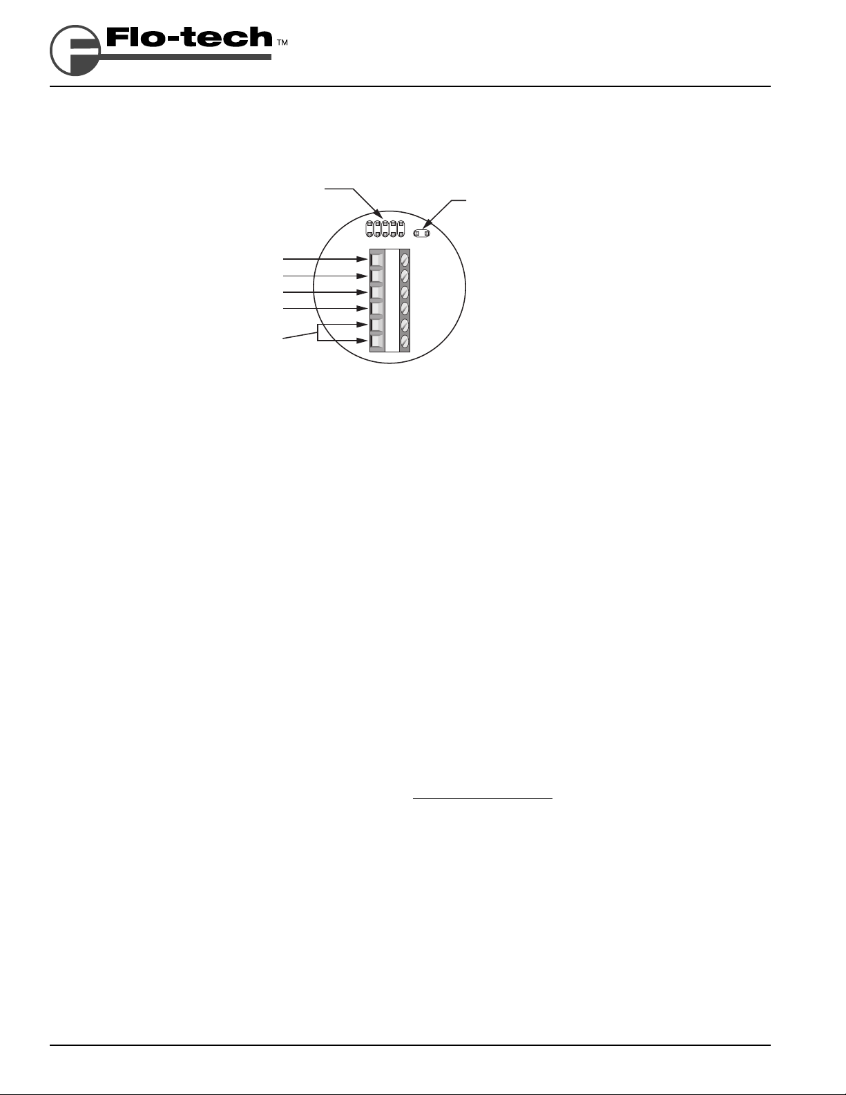
frequency output from a turbine meter into a scaled square wave output signal. Refer to Figure 1 below for the I/O terminal
connections. The board connections include Power Input, Turbine Meter Input, and the Pulse Output to a totalizing device.
PROGRAMMING
PORT
–
OUTPUT
+
OUTPUT
–
VIN
+
8.5 - 30 VDC
VIN
TURBINE
PICK-UP
1 2 3 4 5 6
INTERNAL 3.6K PULL-UP
RESISTOR JUMPER
Figure 1
Board Connections
Enclosure Mounting
The enclosure has four (4) mounting holes for easy mounting.
Power
The K-Factor Scaler requires 8.5 - 30 VDC to operateand is protected by a diode. Polarity is shown in Figure 1 above.
Turbine Meter
The turbine meter connections are non-polarized. Shielded twisted pair wire is recommended for this connection to the turbine
meter.
Pulse Output
Either the internal or external pull-up resistor must be used for the K-Factor Scaler to provide an output pulse. This option is
controlled by the onboard jumper. With the jumper installed, the internal pull-up resistor is connected.
Internal Pull-up Resistor
The internal pull-up resistor allows for simple installation but care must be taken to ensure that the device being connected
to by the pulse output can handle voltage levels as high as the supply feeding the K-Factor board. Another important setup
consideration when using the internal pull-up resistor is to make sure the output pulse from the K-Factor board can supply
enough current for the receiving device to be able to read the pulse. The available current that the K-Factor board can
supply to the receiving device can be calculated with the following equation.
Input Voltage - 0.7 V
Available Current =
Verify that the receiving device input current requirement is below this value for proper operation. Otherwise, an external
pull-up resistor less then 3.6K will have to be used.
External Pull-up Resistor
Using an external pull-up resistor o ers the end user greater exibility of controlling the output pulse provided by the
K-Factor board to the receiving device. Since power sources and receiving devices di er between users, di erent resistor
values may be required by di erent setups.
The external pull-up resistor is connected between the receiving device’s input and external power source. This power
source would be the maximum input voltage (of the pulse) to the receiving device. Refer to the following equation to help
determine the resistor value needed.
§
¨
3600 Ω + 47 Ω
©
§
¨
©
Page 4 Form #FLIT 555 11/10
Page 5
K-Factor Scaler
Installation & Operating Instructions
Supply Voltage
§
R =
¨
©
Where: R = Resistor value in Ohms
Supply Voltage = External supply voltage connected to the external pull-up resistor
I = Input current required by the receiving device in amps
After the Resistor value has been calculated, make sure in the following equation, that “P” is less than or equal to 0.25. “P”
represents the power capability of the output and should not exceed 0.25 Watts. Exceeding this value could damage the
K-Factor board. Raising the Resistor value will decrease the available power output.
P = ( Supply Voltage )
I
Supply Voltage
§
¨
©
§
¨
©
R + 47
§
¨
©
STARTUP and CONFIGURATION USING OPTIONAL PROGRAMMING SOFTWARE KIT (F5141)
The programmable K-Factor Scaler can be factory or user con gured through a serial port of a PC by a Windows® compatible
software utility. A programming adapter is required that interfaces the serial port from the PC to the programming port on the
board.
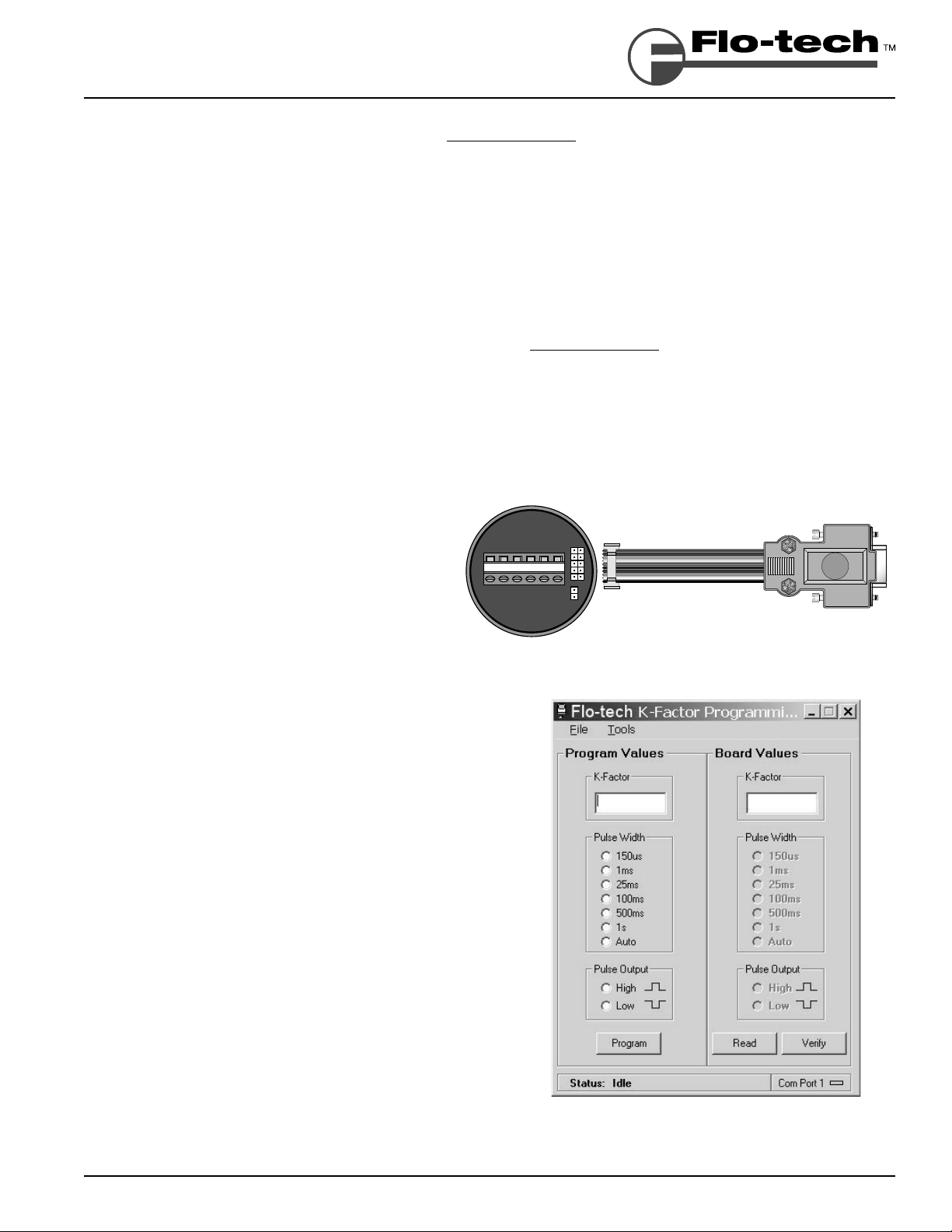
To program the K-Factor Scaler, begin with the power
turned o and connect the adapter cable to the K-Factor
Scaler board. See Figure 2. Then, connect the Serial -toTTL converter (black box) to the adapter cable. Next,
attach the serial extension cable to the Serial-to-TTL
converter and connect the opposite end to an available
9-pin serial port of a PC. Lastly, make sure power is being
supplied. Power must be supplied to the K-Factor Scaler
in order to program.
The programming software is divided into two columns as shown
in Figure 3. The ‘Program Values’ column is the information that is
to be programmed into the K-Factor board and can be entered by
the user. The ‘Board Values’ column is Read ONLY and indicates the
information that the K-Factor board currently contains. The ‘Board
Values’ column will only display the contents of the board after a
program, read, or verify function was performed.
The proper computer serial port must be selected within the
K-Factor Programming software for it to communicate with the
board. This is done by going to TOOLS – COM PORT, from the
menu bar, and selecting the Com Port (1 through 16) that the serial
programming cable is connected to on the computer.
If the serial port selected is invalid, the software will show the
message “ERROR- Invalid Com Port” when trying to program the
board. If the serial port selected is the incorrect port (or if there is
a problem with the cable), the software will show the message “<<
No Response>>” after trying to program the board. All information
under the ‘Program Values’ column must be entered before the
software will allow the board to be programmed.
123456
Figure 2
Interface connection
The PROGRAM button programs the K-factor, Pulse Width, and
Pulse Output to the K-Factor board. After the program function is
complete, the board is automatically read and veri ed. The K-Factor
board will retain these values when disconnected from power and
can be re-programmed at any time.
Form #FLIT 555 11/10 Page 5
Programming software screen
Figure 3
Page 6

K-Factor Scaler
Installation & Operating Instructions
The READ button reads the current information from the K-Factor board and displays it under the ‘Board Values’ column of the
PC software.
The VERIFY button performs the same function as the READ button but compares the Board Values to the Program Values and
displays an error if the two do not match.
Con guring and programming the K-Factor board consists of the following four items:
• Setting the K-factor (divider)
• Setting the output pulse width
• Setting the output level normally high or normally low
• Setting the pulse to use the internal or external pull-up resistor
Setting the K-factor
The K-factor is the ratio of input pulses per each output pulse and can be viewed as a divisor. The minimum K-factor can be set
to 1 where each input pulse yields an output pulse. The maximum K-factor can be set to 999,999,999 where it would take this
many input pulses to yield one output pulse.
The K-factor is set by entering it into the ‘Program Values’ column of the software under K-Factor. The K-factor will be programmed
into the board when the Program button is pressed, but note that all values must be entered before programming is allowed
by the software.
Setting the output pulse width
The output pulse width is the length of time the pulse remains active before resetting to its resting state. The K-Factor has a total
of six di erent pulse widths to choose from. Some end devices require that the pulse be a certain length or longer in order for
proper detection of each incoming pulse. For these devices, it’s important to select a pulse width that is long enough for the
end device to recognize.
The pulse width option is set by selecting the desired pulse width radio button in the ‘Program Values’ column of the software.
The Pulse Width option will be programmed into the board when the Program button is pressed, but note that all values must
be entered before programming is allowed by the software.
In addition to six pre-set pulse widths to choose from, another option is also available called "Auto” mode. This mode acts in the
same manor but does not restrain the output pulse to a speci c length. Instead, it varies and is dependent on output frequency.
The higher the output frequency, the shorter the pulse width output. The lower the frequency output, the longer the pulse
width output. This option turns o the ‘Pulse Output’ option because it does not apply in this mode.
Setting the output level normally high or normally low
Most end devices will be una ected by this setting, but the K-Factor Scaler has the ability to invert the output pulse level. This
option is set by selecting the desired pulse output radio button in the ‘Program Values’ column of the software. The Pulse Output
option will be programmed into the board when the Program button is pressed, but note that all values must be entered before
programming is allowed by the software.
When the Pulse Output option “High” is selected, the output level is normally low and the duration of the selected pulse width
is high. When the Pulse Output option “Low” is selected, the output level is normally high and the duration of the selected pulse
width is low.
Setting the output pulse to use the internal or external pull-up resistor
Either the internal pull-up resistor or an external resistor must be used for the K-Factor Scaler to provide an output pulse. This
option is controlled by the onboard jumper and not by software.
With the jumper installed, the internal 3.6K pull-up resistor is connected to the input voltage of the board. With the jumper
uninstalled, the internal pull-up resistor is disconnected and an external pull-up resistor and supply voltage is required.
Page 6 Form #FLIT 555 11/10
Page 7

K-Factor Scaler
Installation & Operating Instructions
Return Goods Authorization
When returning equipment for service, a Returned Goods Authorization (RGA) number must be obtained
from our Service Department. Please contact them by phone at 800-433-5263 or 262-639-6770 or by e-mail
to [email protected].
All returns go to the following address and must include the RGA number on the outside of the box:
Flo-tech
Division of Racine Federated Inc.
8635 Washington Avenue
Racine, WI 53406-3738 USA
Attn: RGA # xxx-xxxx
Waste Electrical and Electronic Equipment (WEEE) Directive
In the European Union, this label indicates that this product should not be disposed of with household
waste. It should be deposited at an appropriate facility to enable recovery and recycling.
For information on how to recycle this product responsibly in your country, please visit:
www.racinefed.com/recycle/
Form #FLIT 555 11/10 Page 7
Page 8

Flo-tech
Division of Racine Federated Inc.
Limited Warranty and Disclaimer
Flo-tech, Division of Racine Federated Inc. warrants to the end purchaser, for a period of one year from the
date of shipment from the factory, that all ow meters manufactured by it are free from defects in materials
and workmanship. This warranty does not cover products that have been damaged due to misapplication,
abuse, lack of maintenance, or improper installation. Flo-tech’s obligation under this warranty is limited to
the repair or replacement of a defective product, at no charge to the end purchaser, if the product is inspected
by Flo-tech and found to be defective. Repair or replacement is at Flo-tech’s discretion. A returned goods
authorization (RGA) number must be obtained from Flo-tech before any product may be returned for warranty
repair or replacement. The product must be thoroughly cleaned and any process chemicals removed before
it will be accepted for return.
The purchaser must determine the applicability of the product for its desired use and assumes all risks in
connection therewith. Flo-tech assumes no responsibility or liability for any omissions or errors in connection
with the use of its products. Flo-tech will under no circumstances be liable for any incidental, consequential,
contingent or special damages or loss to any person or property arising out of the failure of any product,
component or accessory.
All expressed or implied warranties, including the implied warranty of merchantability and the implied
warranty of tness for a particular purpose or application are expressly disclaimed and shall not apply
to any products sold or services rendered by Flo-tech.
The above warranty supersedes and is in lieu of all other warranties, either expressed or implied and all other
obligations or liabilities. No agent or representative has any authority to alter the terms of this warranty in
any way.
8635 Washington Avenue Racine, WI 53406-3738 USA
Tel: 800-433-5263 or 262-639-6770
o-tech.com
Fax: 800-245-3569 or 262-639-2267
E-Mail: [email protected]
Materials and speci cations subject to change without notice.
Flo-tech is a trademark of Racine Federated Inc.
WINDOWS is a registered trademark of Microsoft Corp.
UL is a registered trademark of Underwriters Laboratories.
© 2010 Racine Federated Inc.
All rights reserved.
Printed in USA
Form #FLIT 555 11/10
 Loading...