

FloTech FT151, FT150, FT155, FT152 Instruction Manual

Instruction Manual 10159
Thermo-Optic Sensors and Thermistor Dummy
PRODUCT DESCRIPTIONS:
These instructions cover the following FloTech products:
FT150 Replacement Thermo-Optic Overfill Probe
FT151 Thermo-Optic Sensor with 2”NPT Probe Holder
FT155 Electronic 5 Channel Dummy
FT152 2 Wire Thermo-Optic Retain Sensor with ½” NPT Probe Holder
FloTech Thermo-Optic sensor and Thermistor Dummy are mechanically and functionally
compatible with Civacon Thermistor, Thermo-Optic and Thermistor Dummy components.
These “Electronic” Thermistor sensors will provide reliable operation when installed as
replacements to conventional “Green Tipped” Thermistor sensors. FloTech Thermo-Optic
sensors and electronic dummy provide high reliability, long life, and quick start up in cold
weather. “Civacon” is a registered trademarks of Civacon / Dover Corporation.
INSTALLATION INSTRUCTIONS:
FloTech model FT151 can be mounted in a 2”NPT female pipe coupling or through a 2 3/8”
hole. When mounting in a 2 3/8” hole the gasket and lock nut provided are used to retain the
probe holder in the tank shell or manhole. After the sensor is mounted remove the cap.
Loosen the probe clamp screw and adjust the probe to the correct level point. This is typically
3% of compartment volume. It is not recommended cutting the standard 7” sensor to a shorter
length. This will cause insufficient time to stop the flow of product within the load racks
reaction time.
IMPORTANT: The actual sensing point adjustment should be determined by the total
response time required to prevent a tank overfill condition. The FloTech sensor reaction time
is one half second. The loading rack will also have a reaction time. Once the probe is adjusted
to the proper height, tighten the clamp screw.
4740T Interstate Dr. Cincinnati, OH 45246
Rev: May 2017 PH: 513 874 8499 FX: 513 874 8399 Page 1
Dixon Bayco

WIRING INSTRUCTIONS:
It is highly recommended to use FloTech FT401 jacketed 7-conductor cable when wiring a
new system. FloTech cable is designed to be oil, UV, and abrasion resistant. We incorporate
a noble tin plated stranded copper wire which resist corrosion. These features will provide
years of reliable service.
After all sensors are mounted in each compartment, align the conduit openings so they face
the roll over rail. Thread in cable glands and pull a length of cable through the conduit
openings between each sensor. Cut to length leaving approximately 8 inches extra length
exiting the top of each probe holder.
All sensor wires must enter or leave the probe holder through one of the ½ NPT openings.
Use FloTech FT402 ½ NPT cable glands to ensure a water tight seal. Unused conduit
openings must have a ½ NPT pipe plug installed. Use pipe dope on all ½ NPT threads to
ensure a water tight seal.
Wire the sensor according to diagram F1 below. Double check your wiring connection when
complete. NOTE: It is highly recommended to use a small amount of Silicone RTV sealant
in each crimp connection. Fill the FloTech butt end crimps with Silicone RTV sealant prior
to inserting the wires then crimp. This will provide a watertight and vibration resistant
connection.
When wiring is complete, replace each sensor cap and o-ring. CAUTION: Do not pinch a
sensor wire when installing the cap.
Rev: May 2017 PH: 513 874 8499 FX: 513 874 8399 Page 2
4740T Interstate Dr. Cincinnati, OH 45246
Dixon Bayco
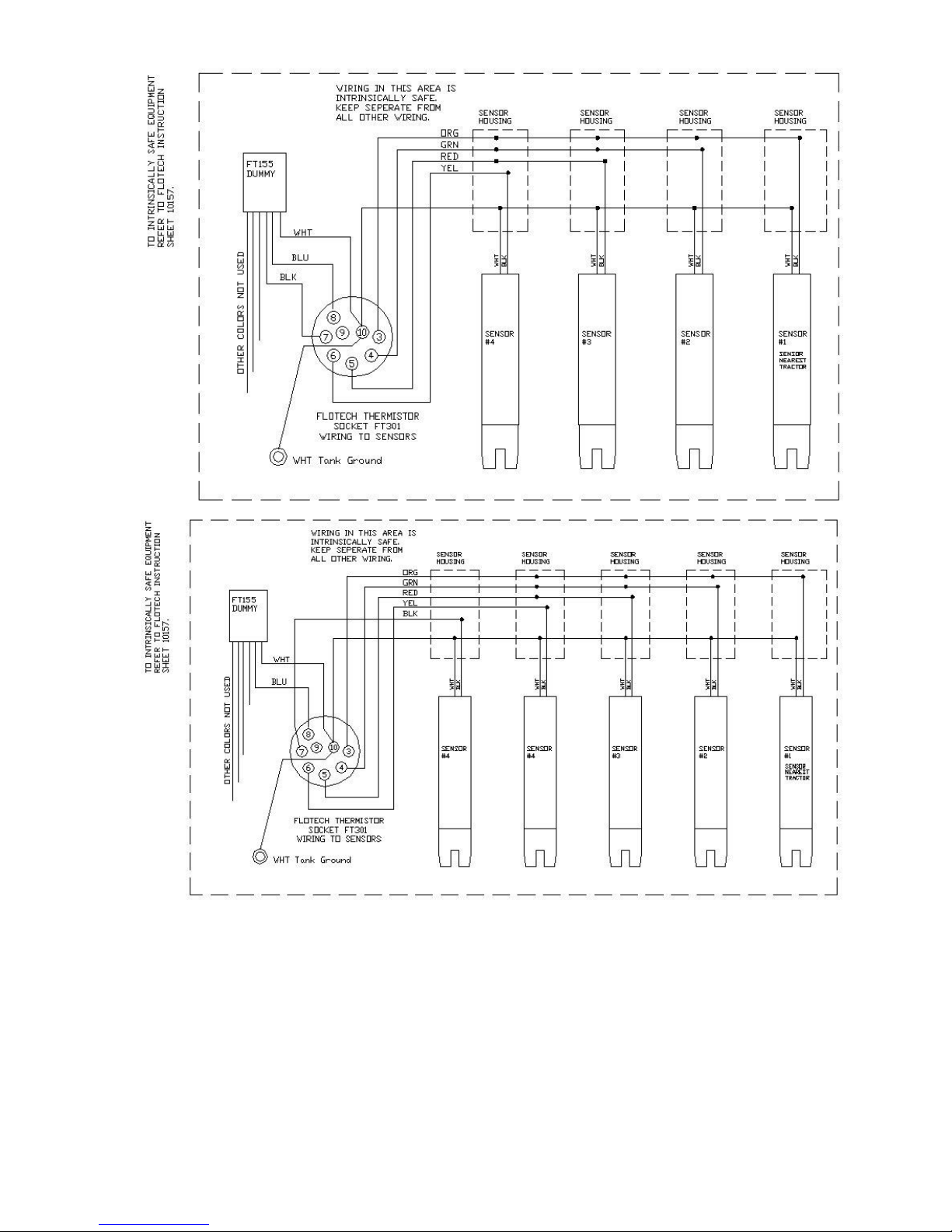
Diagram F1
Rev: May 2017 PH: 513 874 8499 FX: 513 874 8399 Page 3
Dixon Bayco
4740T Interstate Dr. Cincinnati, OH 45246
 Loading...