

FloTech FT150S, FT151S, FT155 Instruction Manual

Instruction Manual 10564
SST Thermo-Optic Sensors and Thermistor Dummy
2 Wire Black & White
PRODUCT DESCRIPTIONS:
These instructions cover the following FloTech products:
FT150S Replacement SST Thermo-Optic Overfill Probe
FT151S SST Thermo-Optic Sensor with 3”NPSM Probe Holder
FT155 Electronic 5 Channel Dummy
FloTech Thermo-Optic sensor and Thermistor Dummy are mechanically and functionally
compatible with Scully Thermistor, Thermo-Optic and Thermistor Dummy components.
These “Electronic” Thermistor sensors will provide reliable operation when installed as
replacements to conventional “Green Tipped” Thermistor sensors. FloTech Thermo-Optic
sensors and electronic dummy provide high reliability, long life, and quick start up in cold
weather.
INSTALLATION INSTRUCTIONS:
FloTech model FT151S can be mounted on a 3”NPT male pipe nipple. After the sensor is
mounted remove the lid.
To adjust sensor length, use ¾” NPT pipe nipples cut and threaded to desired length. Use
Teflon pipe dope or pink Teflon tape to seal the threads.
IMPORTANT: The actual sensing point adjustment should be determined by the total
response time required to prevent a tank overfill condition. The FloTech sensor reaction time
is one half second. The loading rack will also have a reaction time.
Rev: Oct 2008 PH: 513 874 8499 FX: 513 874 8399 Page 1
4740T Interstate Dr. Cincinnati, OH 45246
Dixon Bayco

WIRING INSTRUCTIONS:
It is highly recommended to use FloTech FT400 jacketed 5-conductor cable when wiring a
new system. FloTech cable is designed to be oil, UV, and abrasion resistant. We incorporate
a noble tin plated stranded copper wire which resist corrosion. These features will provide
years of reliable service.
After all sensors are mounted in each compartment, align the conduit openings so they face
the roll over rail. Thread in cable glands and pull a length of cable through the conduit
openings between each sensor. Cut to length leaving approximately 8 inches extra length
exiting the top of each probe holder.
All sensor wires must enter or leave the probe holder through one of the ½ NPT openings.
Use FloTech FT402 ½ NPT cable glands to ensure a water tight seal. Unused conduit
openings must have a ½ NPT pipe plug installed. Use pipe dope on all ½ NPT threads to
ensure a water tight seal.
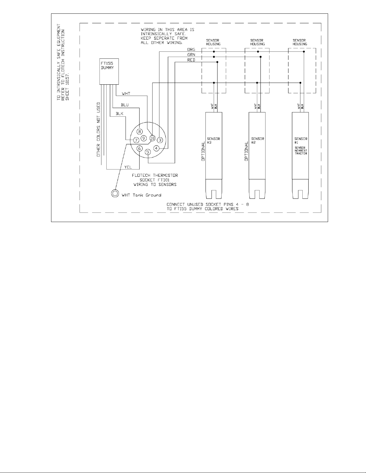
Wire the sensor according to diagram F1 below. Double check your wiring connection when
complete. NOTE: It is highly recommended to use a small amount of Silicone RTV sealant
in each crimp connection. Fill the FloTech butt end crimps with Silicone RTV sealant prior
to inserting the wires then crimp. This will provide a watertight and vibration resistant
connection.
When wiring is complete, replace each sensor lid and o-ring. CAUTION: Do not pinch a
sensor wire when installing the lid.
Rev: Oct 2008 PH: 513 874 8499 FX: 513 874 8399 Page 2
4740T Interstate Dr. Cincinnati, OH 45246
Dixon Bayco
NEED TECHNCIAL ASSITANCE? 877 582 3569
In The United States In Canada
Dixon Bayco USA Dixon Bayco LTD.
800 High St. 2315 Bowman ST.
Chestertown, MD 21620 Innisfil, Ontario, L9S 3V6 Canada
Toll Free: 800 355 1991 Toll Free: 800 355 1991
Fax: 800 283 4966 Office: 705 436 1125
Fax: 705 436 6251
Dixon Bayco
4740T Interstate Dr. Cincinnati, OH 45246
Rev: Oct 2008 PH: 513 874 8499 FX: 513 874 8399 Page 3
 Loading...