

Flo-tech Flo-Check USB Installation & Programming Instructions

Hydraulic System Analyzer
Installation & Programming Instructions
8635 Washington Avenue ■ Racine, WI 53406
Tel: 800-433-5263 or 262-639-6770
Fax: 800-245-3569 or 262-639-2267
E-Mail: info@fl o-tech.com
www.fl o-tech.com


Flo-Check® USB Hydraulic System Analyzer
Installation & Programming Instructions
Table of Contents
Overview..........................................................................................................................................................................4
Specifi cations ..................................................................................................................................................................4
Material .....................................................................................................................................................................4
Power ........................................................................................................................................................................5
Environmental ...........................................................................................................................................................5
Performance .............................................................................................................................................................5
Calibration .................................................................................................................................................................5
Model Number Designations .....................................................................................................................................6
General Information ..................................................................................................................................................6
Installing the Software .....................................................................................................................................................7
Connecting the Hydraulic Analyzer to Your Computer for the First Time.........................................................................7
Software Overview ..........................................................................................................................................................8
Running the Software and Viewing Real-Time Data .......................................................................................................9
Recording Measurements to a File..................................................................................................................................9
To Record a File ......................................................................................................................................................10
To Start Recording a File while in Run Mode ..........................................................................................................11
When Entering Run or Record Mode ......................................................................................................................11
Recording Modes ....................................................................................................................................................11
Log Interval ....................................................................................................................................................................12
Changing Measurement Units .......................................................................................................................................12
Using the Graph ............................................................................................................................................................13
Viewing Graph History ............................................................................................................................................13
Displaying and Hiding Individual Graph Plots .........................................................................................................13
Adjusting the Graph Scales ....................................................................................................................................13
Displaying Graph Gridlines .....................................................................................................................................13
Clearing the Graph ..................................................................................................................................................13
Using the Alarms ...........................................................................................................................................................13
Changing Alarm Settings ........................................................................................................................................14
Resetting the Alarms ...............................................................................................................................................14
Viewing Alarm History .............................................................................................................................................15
Saving/Loading Software Confi gurations ......................................................................................................................16
To Save a Software Confi guration ..........................................................................................................................16
To Load a Software Confi guration ...........................................................................................................................16
Calibration .....................................................................................................................................................................17
To Reset Zero for the Pressure Transducer ............................................................................................................17
To Reset Factory Calibration Defaults ....................................................................................................................17
Test Procedures.............................................................................................................................................................18
Standard Test Conditions ........................................................................................................................................18
"Tee" Test ................................................................................................................................................................18
Inline System Test ...................................................................................................................................................20
Control Valve and Bi-directional Hydraulic Motor Test ............................................................................................21
Bi-directional Cylinder Test......................................................................................................................................23
Hydrostatic Transmission Diagnostics ....................................................................................................................24
Other Test Procedures ............................................................................................................................................25
Maintenance / Troubleshooting .....................................................................................................................................26
Load Valve ..............................................................................................................................................................26
Flow .........................................................................................................................
Burst Discs ..............................................................................................................................................................26
Flow vs Pressure Drop Charts.......................................................................................................................................28
Return Goods Authorization ..........................................................................................................................................29
Waste Electrical and Electronic Equipment (WEEE) Directive ......................................................................................29
Warranty ........................................................................................................................................................................30
...............................................26
Form No. 05-SGN-PM-00191 02/12 Page 3

Flo-Check® USB Hydraulic System Analyzer
Installation & Programming Instructions
Overview
The Flo-Check® USB Hydraulic System Analyzer can be used as a stationary or portable tester for both industrial
and mobile hydraulic system diagnostics, and analysis of the prognostic health of a hydraulic system. It features fl ow,
pressure, and temperature sensors that are monitored by a data acquisition module. This module records the operating
parameters of the system and transfers them to the user’s laptop via the USB port.
The custom software utility is a Windows
and Windows 2000. This intuitive software confi gures the displayed information into user-selected engineering units
and provides real-time graphics with instantaneous readings and trends for all three measurement parameters. The
software also permits the data to be saved for export into a spreadsheet program.
The Hydraulic System Analyzer is powered through the USB port of a PC making it easy to setup and ideal for portable
applications. Interfaced to the PC application, the Hydraulic Analyzer offers a straightforward method of monitoring
system parameters complete with data acquisition.
®
-based application which is compatible with Windows Vista®, Windows XP
Specifi cations
Material
Housing: 6013-T351 Anodized aluminum
Turbine Rotor: T416 Stainless steel
Rotor Supports: 6061-T6 Aluminum
Seals: Viton
Ball Bearings: 440 C Stainless steel
Hub Cones: 6061-T6 Aluminum alloy
Temperature Probe: T303 Stainless steel
Valve: 12L14 Steel body with 303 SS seat
Spool/Sleeve: 12L14 Steel
Straightening Sections: 6061-T6 Aluminum
Ports: SAE Straight thread O-ring boss, female, J1926/1; BSPP ISO1179
Magnetic Pick-up
Body: 12L14 Steel, electroless nickel plate
Nut: 12L14 Steel, electroless nickel plate
Electronic Case: Cold rolled steel, black zinc plate with clear seal
®
standard; EPR optional
Power
USB Power: +5 VDC (supplied through USB port of a PC)
USB Voltage Tolerance: +4.6 VDC min, +5.25 VDC max
Current: 100 mA, typ
Environmental
Pressure Rating: 6000 PSI (414 Bar) maximum with a 3:1 safety factor;
capable of 10,000 PSI (689 Bar) transients
Operating Pressure: <6000 PSI (414 Bar, 41.4 MPa, 420 kg/cm²);
capable of 10,000 PSI (689 Bar) transients
Internal Valve By-pass: 7500 PSI DP
Pressure Drop: See ∆P charts on page 28
Fluid Temperature: -4 to +300 °F (-20 to +150 °C)
Ambient Temperature: +32 to +185 °F (0 to +85 °C)
Storage Temperature: -40 to +185 °F (- 40 to +85 °C)
Humidity: 0-90%, non-condensing
Page 4 Form No. 05-SGN-PM-00191 02/12
Flo-Check® USB Hydraulic System Analyzer
Installation & Programming Instructions
Performance
Flow
Accuracy: <±1% of reading @ 32 cSt
Repeatability: ±0.2%
Pressure
Accuracy: <±0.5% BFSL
Stability: <±0.25% of full scale
Zero Offset: <±2% of full scale
TC Zero and TC Span: <±1.5% of full scale
Response Time: 0.2 milliseconds
Temperature
Absolute Error: ±2.7 °F (±1.5 °C)
(over range of 0 to 185 °F)
Nonlinearity: ±0.7 °F (±0.4 °C)
Repeatability: ±0.2 °F (±0.1 °C)
Data Acquisition
Sample Rate: 10 kHz
PC Screen Update/Record Rate
Flow: 1 second (average 10K samples)
Temperature: 1 second (average 10K samples)
Pressure: 1 second (min, max, average 10K samples)
Calibration
Testers are calibrated with 0.876 specifi c gravity, 150 SUS (32 cSt) Mobil / DTE 24 hydraulic oil. Standard calibration
is done using 5 points and is traceable to NIST, ISO 9001. An optional 10 point calibration can be performed for
increased accuracy.
Model Number Designations
MODEL
NUMBER
F7164 SAE 12 2 - 30 GPM
F7160 SAE 16 3 - 85 GPM
F7161 SAE 24 7 - 199.9 GPM
F7165 G-3/4 7.5 - 113.6 LPM
F7162 G-1 15 - 321 LPM
F7163 G-1-1/2 26 - 757 LPM
NOMINAL
PORT SIZE
FLOW
RATE
Form No. 05-SGN-PM-00191 02/12 Page 5
Flo-Check® USB Hydraulic System Analyzer
Installation & Programming Instructions
CAUTION
Read instructions thoroughly before installing the tester. If you have any questions regarding product installation or
maintenance, call your local supplier or the factory for more information.
General Information
The power measurements are derived from the product of fl ow and pressure.
H.P. = GPM × PSI H.P. = liters/min × kg/cm²
1714 456.2
H.P. = liters/min × Bar H.P. = liters/min × MPa
447.40 44.74
kW = liters/min × kg/cm² kW = liters/min × Bar
611 600
kW = liters/min × MPa
60
1. Make all tests at the same operating temperature to ensure consistency of results. A typical operating
temperature for mobile machinery is 150 °F (66 °C).
2. Testing will be easier and faster if quick disconnect couplers are used to install the Flo-Check USB Hydraulic
System Analyzer.
3. Complete descriptions of the following basic hydraulic tests using the Flo-Check USB Hydraulic System
Analyzer can be found starting on page 18:
a. "Tee" Test
b. Inline System Test
c. Control Valve and Bi-directional Hydraulic Motor Test
d. Bi-Directional Cylinder Test
e. Hydrostatic Transmission Diagnostics
CAUTION
The information in this manual is for general application only. Any information furnished by the manufacturer of the
machine’s hydraulic components should be followed. Specifi c systems may require specifi c test procedures.
4. A preliminary check of the hydraulic system’s oil supply, pump speed, oil lines, and cylinder rods, as well as
an external leak check, should be made prior to installing the Flo-Check.
Page 6 Form No. 05-SGN-PM-00191 02/12

Flo-Check® USB Hydraulic System Analyzer
Installation & Programming Instructions
Installing the Software
To install the software package on your computer, perform the following steps:
1. Close all applications you have running.
2. Insert the Flo-Check USB Hydraulic System Analyzer CD into your CD drive.
If you have the auto-run feature enabled on your computer, the installation prompts will automatically be
displayed.
Note: If auto-run is not enabled, use Windows Explorer to navigate to the root directory on the CD. Doubleclick on the setup.exe fi le to begin the installation.
3. Follow the installation prompts to complete the installation.
4. After a successful installation, a dialog will be displayed asking to restart the computer.
Select Yes.
Note: If you wish to wait to reboot the computer, select ‘No’. However, you will need to reboot before initial
use for proper operation.
5. The installation creates two shortcuts on the computer; one on the desktop and the second in the START –
PROGRAMS – FLO-TECH Windows menu.
Connecting the Hydraulic Analyzer to Your Computer for the First Time
The Flo-Check USB Hydraulic System Analyzer connects to your computer through a USB port. A cable is shipped
with the unit, but any standard USB A Male to USB B Male cable can be used. The initial connection is easy and uses
standard drivers within Windows that do not require special driver installation by the operator.
► The Hydraulic Analyzer interface uses the Microsoft Human Interface Driver (HID). This driver is installed
with Windows operating systems that support USB.
► The fi rst time you connect the device to your PC, your computer automatically detects it and confi gures the
necessary drivers. No third-party device drivers need to be installed.
► The Hydraulic Analyzer interface is plug-and-play. You can connect it to the computer before or after you
install the software, and without shutting the computer off.
Note: Before connecting the Hydraulic Analyzer to the computer, download and install the latest Microsoft Windows
updates. For Windows XP, there is a Hotfi x KB822603 that is installed to address a serious error within Windows XP
and the use of USB devices.
To connect the Hydraulic Analyzer to your computer:
1. Connect the USB cable to the Hydraulic Analyzer and then plug the other end into a USB port on the
computer.
2. The fi rst time the Hydraulic Analyzer is connected to the computer, several “Found New Hardware” balloons
or dialogs pop up. This is normal.
3. Once the Hardware has been found and installed, the last balloon or dialog states “Your new hardware is
installed and ready to use.” At this point, the Hydraulic Analyzer interface has been successfully installed and
can be used with the software application.
Form No. 05-SGN-PM-00191 02/12 Page 7
Flo-Check® USB Hydraulic System Analyzer
Installation & Programming Instructions
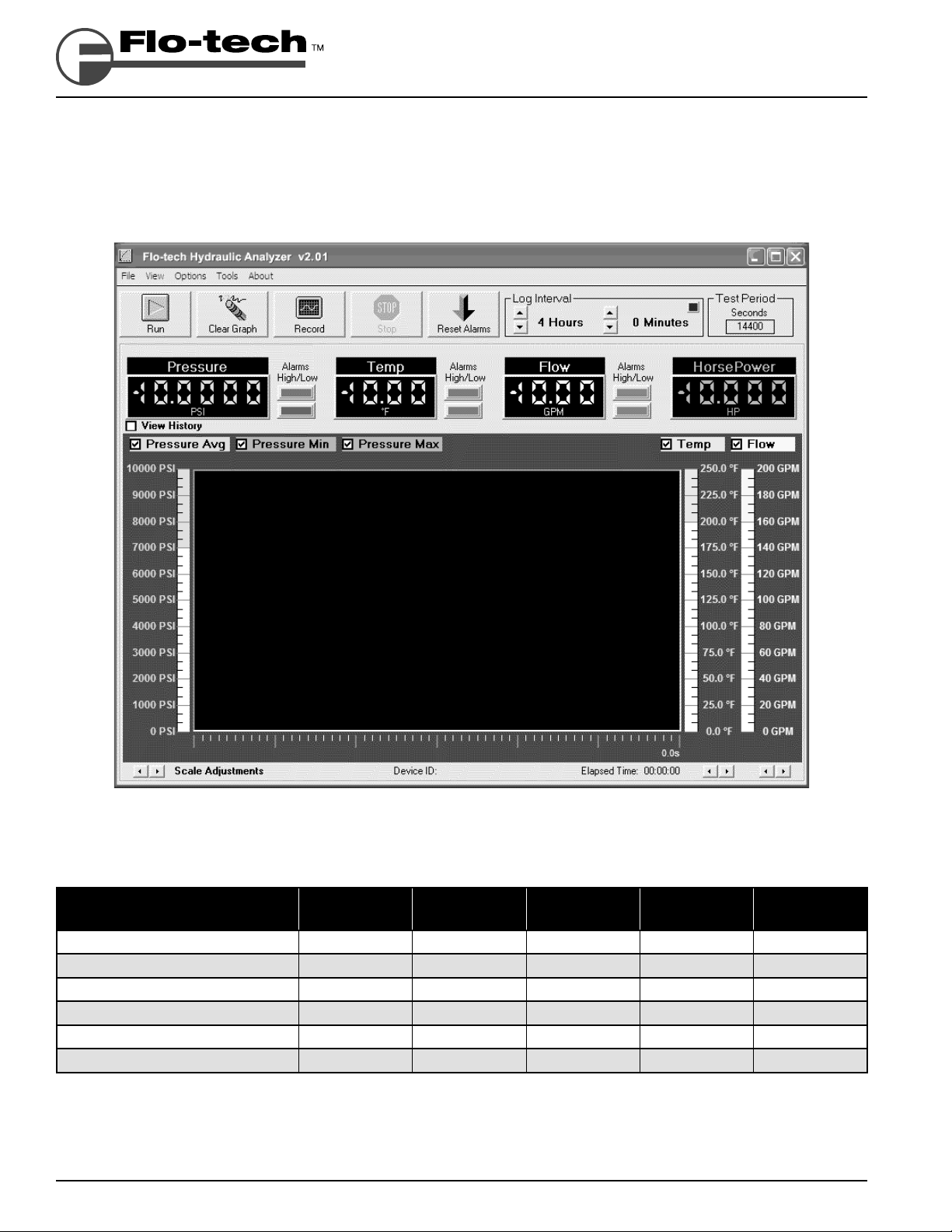
Software Overview
The software provides a real-time graphical and digital interface for monitoring and/or recording pressure, temperature,
and fl ow rate parameters from the Hydraulic Analyzer. In addition to the graphical and digital displays, the main screen
also consists of a menu bar, buttons with common functions, and alarm indicators.
FIGURE 1 - Flo-Check USB Hydraulic Analyzer Screenshot
Measurement
(over a 1 second time period)
Average Pressure Green ●●●●
Minimum Pressure Dark Green ●●
Maximum Pressure Dark Green ●●
Average Temperature Blue ●●●●
Average Flow Rate Yellow ●●●●
Average Power Orange ●●
TABLE 1 - Measurement Display and Record Features
Page 8 Form No. 05-SGN-PM-00191 02/12
Color
Indication
Alarm
Indication
Digital
Indication
Graphical
Display
Record to
File
Flo-Check® USB Hydraulic System Analyzer
Installation & Programming Instructions
Running the Software and Viewing Real-Time Data
1. Connect the USB cable from the Hydraulic Analyzer to the computer.
Note: This is required before starting the software. This allows the software application to detect a connected
unit.
2. Start the software application by double-clicking on the Flo-tech Hydraulic Analyzer icon on your desktop.
3. Press the Run button.
Data will be displayed on the digital displays and the strip-chart will be updated once per second.
4. Press the Stop button when fi nished to halt the collection of data.
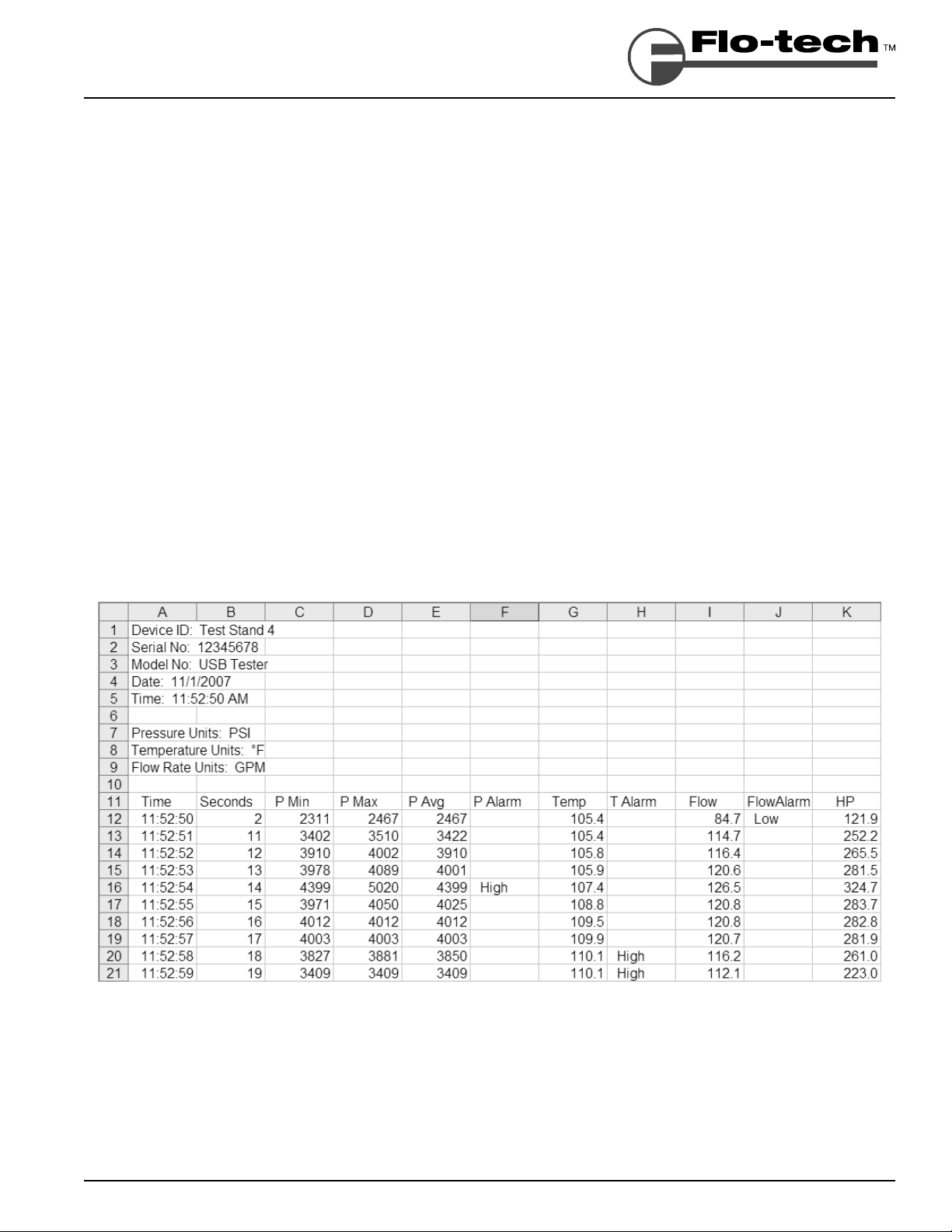
Recording Measurements to a File
All measurements can be saved to a comma separated value (.csv) fi le. This fi le type is a generic text fi le with the data
separated by commas and can be read by many spreadsheet applications such as Excel
These spreadsheet programs can then re-graph and manipulate the data.
All measurements taken (as shown in Table 1 on page 8) are saved once per second to the fi le. For example, recording
for 2 minutes would yield 120 points of data. Even though data points are only recorded once per second, pressure
spikes and dips are captured by recording the maximum or minimum pressure during each measurement period.
Therefore, the precise shape of the pressure spike is not recorded but its amplitude and the time it occurred are both
recorded.
®
and Corel® Quattro Pro®.
FIGURE 2 - Example File
Form No. 05-SGN-PM-00191 02/12 Page 9
Flo-Check® USB Hydraulic System Analyzer
Installation & Programming Instructions
To Record a File
1. Connect the USB cable from the Hydraulic Analyzer to the computer.
Note: This is required before starting the software. This allows the software application to detect a connected
unit.
2. Start the software application by double-clicking on the Flo-tech Hydraulic Analyzer icon on your desktop.
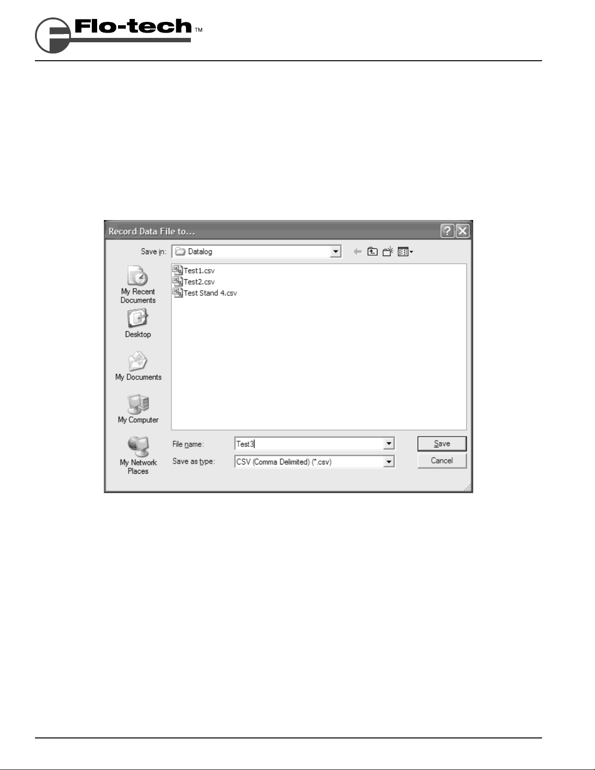
3. Press the Record button.
4. A dialog box will be displayed asking you to name the fi le you wish to create and where to save it. Type a
name in the File Name: textbox and press the Save button.
FIGURE 3 - Record Data File to... Screenshot
Note: The default location for saving a log fi le for Windows XP and Windows 2000 is:
C:\Documents and Settings\<user name>\My Documents\Flo-tech\Hydraulic Analyzer\Datalog
The default location for saving a log fi le for Windows Vista
®
is:
C:\Users\<user name>\Documents\Flo-tech\Hydraulic Analyzer\Datalog
Note: If you wish to record over an existing fi le, double-click on the fi le from the list.
Data will be displayed on the digital displays and the strip-chart will be updated once per second. The message
Recording… is also displayed under the Run button to indicate the software is in Record mode rather than run
mode. It’s important to note that data is not recorded if the fi le is already open by another application such as
®
Excel
.
5. Press the Stop button when fi nished to halt the collection of data.
Page 10 Form No. 05-SGN-PM-00191 02/12
 Loading...