

Flo-tech F6700, F6750 Specifications
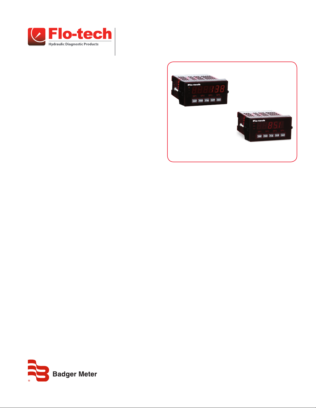
F6600/F6650
F6700/F6750
Digital Displays
F6700/F6750 and F6600/F6650
DESCRIPTION
Flo-tech digital displays are designed for use with Flo-tech
Activa, Ultima and Classic Flow Meters, but can be used with any
frequency or analog output flow meter. The displays are powered
by an AC or DC power source, and can be configured with a variety
of communication protocols and units of measure. Basic functions
include flow, temperature and pressure indication, totalization,
alarm processing, and process control.
In addition to flow rate frequency signals derived from meter,
the F6600/F6650 models accept inputs from switch contacts
and outputs from CMOS or TTL circuits. These displays provide 6
different indications including counter A, counter B, counter C, rate,
rate maximum, and rate minimum. Annunciators indicate which
variable is being displayed.
FEATURES
F6700/F6750
• AC or DC power
• Five digit rate and total display
• 4…20 mA or 0…10V DC input
• Built-in transmitter power supply
• Three expansion card slots
• NEMA 4X/IP 65 rated enclosure
• CE compliant
F6600/F6650
• AC or DC power
• Six digit rate and total display
• Frequency input
• Built-in transmitter power supply
• Three expansion card slots
• NEMA 4X/IP 65 rated enclosure
• CE compliant
APPLICATIONS
Flo-tech digital displays are suitable for several flow metering
applications where remote flow monitoring is required. Typical
applications include:
• Hydraulic diagnostics, monitoring and test stands
• Mobile construction and marine equipment
• General industrial processes
PROGRAMMING
When ordered with a flow meter, flow meter data is configured
and programmed at the factory. Replacement units can be
programmed in the field via the front panel display, or at the
factory if the flow meter serial number is provided.
DSY-DS-02152-EN-02 (August 2016)
Product Data Sheet
Operation
OPERATION
Frequency or analog output signals generated from a flow metering device are interpreted by the display, and then calculated to provide
a volumetric flow rate based on the flow meter properties. Flow rate units are scaled based on the configuration of the display. For flow
sensor arrays that are configured with an additional pressure and/or temperature sensors, the digital displays have available inputs to
accept and display these parameters.
Flow rate, pressure and temperature readings can be transmitted through the various communication protocols.
ADDITIONAL PRODUCTS
Part Number Description Use
F6542 Form C relay module
F5140 K-factor scaler Must be used with Flo-tech flow meters configured with frequency output and sizes SAE 8, G1/4 or equivalent.
OTE:N For additional set point alarm options, consult the factory.
Expansion Cards
The optional plug-in card requires customer installation and setup. Use this feature with a display that includes a
serial communication card (RS-232 or EIA-485).
Analog Output
Communication Optional plug-in cards to facilitate digital communications. See “Model Number” on page 4 for options.
Setpoint Alarms Select from dual FORM-C relays (5 Amp), Quad Form-A relays (3 Amp) or either sinking or sourcing quad open collector logic outputs.
A linear DC output signal card can be set up to provide a 4…20 mA, 0…20 mA or 0…10V DC signals and can be scaled independent
of the input range.
OTE:N The analog output and communication cards will be installed at the factory at the time of order. They may be installed at a later
date if ordered separately. The setpoint alarm cards are available for customer installation and configuration only.
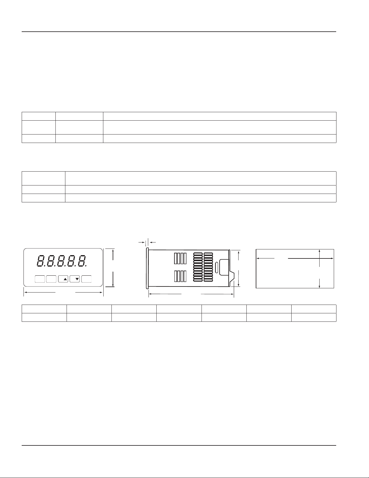
DIMENSIONS
C
MAX
MIN
TOT
SP1 SP2 SP3 SP4
DSP PAR F1 F2 RST
A
A* B* C D E F G
3.80 in. (96.5 mm) 1.95 in. (49.5 mm) 0.10 in. (2.5 mm) 4.10 in. (104.1 mm) 1.75 in. (44.5 mm) 3.62 in. (92.0 mm) 1.77 in. (45.0 mm)
*F6700/F6750 is shown, dimensions are the same for F6600/F6650
B
E
D
Panel cut-out
F
G
Page 2 August 2016 DSY-DS-02152-EN-02
 Loading...