

Page 1

User’s manual
FLIR B6xx series
FLIR P6xx series
FLIR SC6xx series
1558550Publ. No.
a557Revision
English (EN)Language
October 7, 2011Issue date
Page 2

Page 3

Warnings & Cautions
1
Notice to user
Customer help
Documentation updates
Important note about this manual
Parts lists
Quick Start Guide
A note about ergonomics
Camera parts
Screen elements
2
3
4
5
6
7
8
9
10
Connecting external devices
Pairing Bluetooth devices
Handling the camera
Working with views and images
Working with fusion
11
12
13
14
15
Page 4

Page 5

Working with measurement tools
16
Fetching data from external Extech meters
Working with alarms
Annotating images
Programming the camera
Recording video clips
Changing settings
Cleaning the camera
Technical data
Finding the IP address for a camera connected
using a FireWire cable
17
18
19
20
21
22
23
24
25
Dimensional drawings
Application examples
Introduction to building thermography
Introduction to thermographic inspections of
electrical installations
About FLIR Systems
26
27
28
29
30
Page 6

Page 7

Glossary
31
Thermographic measurement techniques
History of infrared technology
Theory of thermography
The measurement formula
Emissivity tables
32
33
34
35
36
Page 8

Page 9

User’s manual
Publ. No. 1558550 Rev. a557 – ENGLISH (EN) – October 7, 2011
Page 10

Legal disclaimer
All products manufactured by FLIR Systemsarewarranted against defectivematerialsandworkmanship for aperiodof one(1)year from the
delivery date of the original purchase, provided such products have been under normal storage, use and service, and in accordance with
FLIR Systems instruction.
Uncooled handheldinfraredcameras manufactured by FLIRSystems are warranted againstdefectivematerials and workmanship fora period
of two (2) years from the delivery date of the original purchase, provided such products have been under normal storage, use and service,
and in accordance with FLIR Systems instruction, and provided that the camera has been registered within 60 days of original purchase.
Detectors foruncooledhandheld infrared cameras manufacturedbyFLIR Systems are warrantedagainstdefective materials and workmanship
for a period of ten (10) years from the delivery date of the original purchase, provided such products have been under normal storage, use
and service, and in accordance with FLIR Systems instruction, and provided that the camera has been registered within 60 days of original
purchase.
Products which are not manufactured by FLIR Systems but included in systems delivered by FLIR Systems to the original purchaser, carry
the warranty, if any, of the particular supplier only. FLIR Systems has no responsibility whatsoever for such products.
The warranty extends only to the original purchaser and is not transferable. It is not applicable to any product which has been subjected to
misuse, neglect, accident or abnormal conditions of operation. Expendable parts are excluded from the warranty.
In the case of adefect inaproduct coveredbythis warrantytheproduct must notbe furtherusedin order toprevent additional damage.The
purchaser shall promptly report any defect to FLIR Systems or this warranty will not apply.
FLIR Systems will, at its option, repair or replace any such defective product free of charge if, upon inspection, it proves to be defective in
material or workmanship and provided that it is returned to FLIR Systems within the said one-year period.
FLIR Systems has no other obligation or liability for defects than those set forth above.
No other warranty is expressed or implied. FLIR Systems specifically disclaims the implied warranties of merchantability and fitness for a
particular purpose.
FLIR Systems shall not be liable for any direct, indirect, special, incidentalor consequential loss or damage, whether basedon contract, tort
or any other legal theory.
This warranty shall be governed by Swedish law.
Any dispute, controversy or claim arising out of or in connection with this warranty, shall be finally settled by arbitration in accordance with
the Rules of the Arbitration Institute of the Stockholm Chamber of Commerce. The place of arbitration shall be Stockholm. The language to
be used in the arbitral proceedings shall be English.
U.S. Government Regulations
The products described in the user documentation may require government authorization for export/re-export, or transfer. Contact FLIR
■
Systems for details.
Depending on license andexportprocedures,lensesmaybe permanently fixedtocamerasshippedtocustomersoutsideUnited States.
■
Interchangeable lenses fall under U.S. Department of State jurisdiction.
Copyright
© 2011, FLIRSystems. All rights reservedworldwide. No parts ofthesoftware including source codemaybe reproduced, transmitted, transcribed
or translated into any language or computer language in any form or by any means, electronic, magnetic, optical, manual or otherwise,
without the prior written permission of FLIR Systems.
This documentation must not, in whole or part, be copied, photocopied, reproduced, translated or transmitted to any electronic medium or
machine readable form without prior consent, in writing, from FLIR Systems.
Names and marks appearing on the products herein are eitherregistered trademarksor trademarksof FLIR Systems and/or its subsidiaries.
All othertrademarks,trade names or companynames referenced herein areusedfor identification only andarethe property of theirrespective
owners.
Quality assurance
The Quality Management System under which these products are developed and manufactured has been certified in accordance with the
ISO 9001 standard.
FLIR Systems is committed to a policy of continuous development; therefore we reserve the right to make changes and improvements on
any of the products described in this manual without prior notice.
Patents
One or several of the following patents or design patents apply to the products and/or features described in this manual:
0002258-2; 000279476-0001; 000439161; 000499579-0001; 000653423; 000726344; 000859020; 000889290; 001106306-0001; 001707738;
001707746; 001707787; 001776519; 0101577-5; 0102150-0; 0200629-4; 0300911-5; 0302837-0; 1144833; 1182246; 1182620; 1188086;
1285345; 1287138; 1299699; 1325808; 1336775; 1365299; 1402918; 1404291; 1678485; 1732314; 200530018812.0; 200830143636.7;
2106017; 235308; 3006596; 3006597; 466540; 483782; 484155; 518836; 60004227.8; 60122153.2; 602004011681.5-08; 6707044; 68657;
7034300; 7110035; 7154093; 7157705; 7237946; 7312822; 7332716; 7336823; 7544944; 75530; 7667198; 7809258; 7826736; D540838;
x Publ. No. 1558550 Rev. a557 – ENGLISH (EN) – October 7, 2011
Page 11

D549758; D579475; D584755; D599,392; DI6702302-9; DI6703574-4; DI6803572-1; DI6803853-4; DI6903617-9; DM/057692; DM/061609;
Registration Number; ZL00809178.1;ZL01823221.3;ZL01823226.4;ZL02331553.9;ZL02331554.7;ZL200480034894.0;ZL200530120994.2;
ZL200630130114.4; ZL200730151141.4; ZL200730339504.7; ZL200830128581.2; ZL200930190061.9
EULA Terms
You have acquired a device (“INFRARED CAMERA”) that includes software licensed by FLIR Systems AB from Microsoft Licensing, GP
■
or its affiliates (“MS”). Those installed software products of MS origin, as well as associated media, printed materials, and “online” or
electronic documentation(“SOFTWARE”)are protected by internationalintellectualproperty laws and treaties.TheSOFTWARE is licensed,
not sold. All rights reserved.
IF YOU DO NOTAGREE TO THISENDUSER LICENSE AGREEMENT(“EULA”), DO NOT USETHEDEVICE OR COPY THE SOFTWARE.
■
INSTEAD, PROMPTLY CONTACT FLIR Systems AB FOR INSTRUCTIONS ON RETURN OF THE UNUSED DEVICE(S) FOR A REFUND.
ANY USE OF THE SOFTWARE, INCLUDING BUT NOT LIMITED TO USE ON THE DEVICE, WILL CONSTITUTE YOUR AGREEMENT
TO THIS EULA (OR RATIFICATION OF ANY PREVIOUS CONSENT).
GRANT OF SOFTWARE LICENSE. This EULA grants you the following license:
■
You may use the SOFTWARE only on the DEVICE.
■
NOT FAULT TOLERANT. THE SOFTWARE IS NOT FAULT TOLERANT. FLIR Systems AB HAS INDEPENDENTLY DETERMINED
■
HOW TOUSE THE SOFTWAREIN THE DEVICE,AND MS HASRELIED UPON FLIRSystems AB TOCONDUCT SUFFICIENT TESTING
TO DETERMINE THAT THE SOFTWARE IS SUITABLE FOR SUCH USE.
NO WARRANTIES FOR THE SOFTWARE. THE SOFTWARE is provided “AS IS” and with all faults. THE ENTIRE RISK AS TO SAT-
■
ISFACTORY QUALITY, PERFORMANCE, ACCURACY, AND EFFORT (INCLUDING LACK OF NEGLIGENCE) IS WITH YOU. ALSO,
THERE ISNO WARRANTY AGAINSTINTERFERENCE WITH YOURENJOYMENT OF THESOFTWAREOR AGAINST INFRINGEMENT.
IF YOU HAVE RECEIVED ANY WARRANTIES REGARDING THE DEVICE OR THE SOFTWARE, THOSE WARRANTIES DO NOT
ORIGINATE FROM, AND ARE NOT BINDING ON, MS.
No Liability for Certain Damages. EXCEPT AS PROHIBITED BY LAW, MS SHALL HAVE NO LIABILITY FOR ANY INDIRECT,
■
SPECIAL, CONSEQUENTIAL OR INCIDENTAL DAMAGES ARISING FROM OR IN CONNECTION WITH THE USE OR PERFORMANCE OF THE SOFTWARE. THIS LIMITATION SHALL APPLY EVEN IF ANY REMEDY FAILS OF ITS ESSENTIAL PURPOSE.
IN NO EVENT SHALL MS BE LIABLE FOR ANY AMOUNT IN EXCESS OF U.S. TWO HUNDRED FIFTY DOLLARS (U.S.$250.00).
Limitations on Reverse Engineering, Decompilation, and Disassembly. Youmaynot reverse engineer,decompile, or disassemble
■
the SOFTWARE, exceptand only to the extentthat such activity isexpresslypermitted by applicable lawnotwithstandingthis limitation.
SOFTWARE TRANSFER ALLOWED BUT WITH RESTRICTIONS. Youmaypermanentlytransferrights under this EULA only aspart
■
of a permanent sale or transfer of the Device, and only if the recipient agrees to this EULA. If the SOFTWARE is an upgrade, any
transfer must also include all prior versions of the SOFTWARE.
EXPORT RESTRICTIONS. You acknowledge that SOFTWARE is subject to U.S. export jurisdiction. You agree to comply with all
■
applicable international andnationallawsthatapplytotheSOFTWARE, includingthe U.S. Export Administration Regulations,aswell
as end-user, end-use and destination restrictions issued by U.S. and other governments. For additional information see
http://www.microsoft.com/exporting/.
Publ. No. 1558550 Rev. a557 – ENGLISH (EN) – October 7, 2011
Page 12

INTENTIONALLY LEFT BLANK
xii Publ. No. 1558550 Rev. a557 – ENGLISH (EN) – October 7, 2011
Page 13

Table of contents
11 Warnings & Cautions .....................................................................................................................
52 Notice to user ..................................................................................................................................
73 Customer help ................................................................................................................................
94 Documentation updates .................................................................................................................
115 Important note about this manual .................................................................................................
136 Parts lists .........................................................................................................................................
136.1 Contents of the transport case .............................................................................................
136.2 List of accessories ................................................................................................................
177 Quick Start Guide ...........................................................................................................................
177.1 Detecting a temperature .......................................................................................................
198 A note about ergonomics ..............................................................................................................
219 Camera parts ...................................................................................................................................
219.1 View from the left ..................................................................................................................
239.2 View from the right ................................................................................................................
259.3 View from the rear .................................................................................................................
279.4 Battery condition LED indicator ............................................................................................
289.5 Power LED indicator .............................................................................................................
299.6 Laser pointer .........................................................................................................................
3110 Screen elements .............................................................................................................................
3110.1 Mode selector .......................................................................................................................
3210.2 Result table and measurement tools ...................................................................................
3310.3 Toolbox, indicators and other objects ..................................................................................
3410.4 Screen elements in infrared images .....................................................................................
3511 Connecting external devices .........................................................................................................
3611.1 Connecting devices to the rear connectors .........................................................................
3811.2 Connecting devices to the front connector ..........................................................................
3911.3 Inserting SD Memory Cards .................................................................................................
4112 Pairing Bluetooth devices ..............................................................................................................
4313 Handling the camera ......................................................................................................................
4313.1 Charging the camera battery ...............................................................................................
4313.1.1 Charging the battery using the power supply cable ............................................
4413.1.2 Charging the battery using the stand-alone battery charger ...............................
13.2.1 Using the combined power supply and battery charger to charge the battery
when it is inside the remote control ......................................................................
13.2.2 Using the combined power supply and battery charger to charge the battery
when it is outside the remote control ...................................................................
Publ. No. 1558550 Rev. a557 – ENGLISH (EN) – October 7, 2011 xiii
4513.2 Charging the remote control battery ....................................................................................
46
47
4813.3 Installing and removing the camera battery ........................................................................
4813.3.1 Installing the battery ..............................................................................................
4913.3.2 Removing the battery ............................................................................................
Page 14

5013.4 Installing and removing the remote control battery .............................................................
5013.4.1 Installing the remote control battery .....................................................................
5213.4.2 Removing the remote control battery ...................................................................
5413.5 Turning on the camera .........................................................................................................
5413.6 Turning off the camera ..........................................................................................................
5413.7 Setting power save mode .....................................................................................................
5513.8 Adjusting the viewfinder eyepiece ........................................................................................
5613.9 Adjusting the viewing angle of the viewfinder ......................................................................
5713.10 Adjusting the viewfinder’s dioptric correction ......................................................................
5813.11 Adjusting the camera grip ....................................................................................................
5913.12 Opening the display .............................................................................................................
6013.13 Adjusting the viewing angle of the display ...........................................................................
6113.14 Installing an infrared lens .....................................................................................................
6213.15 Removing an infrared lens ...................................................................................................
6313.16 Adjusting the infrared camera focus manually ....................................................................
6413.17 Adjusting the infrared camera focus ....................................................................................
6513.18 Autofocusing the infrared camera ........................................................................................
6613.19 Autofocusing the digital camera ...........................................................................................
6713.20 Operating the laser pointer ...................................................................................................
6914 Working with views and images ...................................................................................................
6914.1 Previewing an image ............................................................................................................
7014.2 Saving an image ...................................................................................................................
7114.3 Opening an image ................................................................................................................
7214.4 Using the zoom function ......................................................................................................
7314.5 Using the Panorama function ...............................................................................................
7514.6 Using the pan function .........................................................................................................
7614.7 Adjusting an image ...............................................................................................................
7914.8 Changing maximum and minimum scale values .................................................................
8014.9 Hiding overlay graphics ........................................................................................................
8114.10 Changing the palette ............................................................................................................
8214.11 Associating images ..............................................................................................................
8314.12 Setting & switching reference images ..................................................................................
8514.13 A note about the folder structure .........................................................................................
8614.14 Specifying work folder ..........................................................................................................
8714.15 Creating a new work folder ..................................................................................................
8814.16 Deleting a work folder ...........................................................................................................
8914.17 Deleting an image .................................................................................................................
9014.18 Deleting all images ...............................................................................................................
9115 Working with fusion ........................................................................................................................
9516 Working with measurement tools .................................................................................................
9516.1 Creating & setting up a spotmeter .......................................................................................
9716.2 Creating & setting up a box or circle ....................................................................................
9916.3 Creating & setting up an isotherm .......................................................................................
10116.4 Creating & setting up a line ..................................................................................................
10316.5 Creating & setting up a difference calculation .....................................................................
10416.6 Changing object parameters ................................................................................................
10717 Fetching data from external Extech meters .................................................................................
10917.1 Typical moisture measurement and documentation procedure ..........................................
11118 Working with alarms .......................................................................................................................
xiv Publ. No. 1558550 Rev. a557 – ENGLISH (EN) – October 7, 2011
Page 15

11118.1 General alarms .....................................................................................................................
11318.2 Building alarms .....................................................................................................................
11519 Annotating images ..........................................................................................................................
11619.1 Taking a digital photo ...........................................................................................................
11719.2 Creating a voice annotation .................................................................................................
11919.3 Creating a text annotation ....................................................................................................
12219.4 Adding an image description ...............................................................................................
12520 Programming the camera ..............................................................................................................
12721 Recording video clips ....................................................................................................................
12721.1 Recording non-radiometric video clips ................................................................................
12921.2 Recording radiometric infrared sequence files ....................................................................
13122 Changing settings ..........................................................................................................................
13122.1 Changing IR preferences .....................................................................................................
13122.1.1 Changing temperature range ...............................................................................
13222.1.2 Changing image enhancement filters ..................................................................
13322.2 Changing settings for camera behavior ...............................................................................
13322.2.1 Changing the number of measurement tools ......................................................
13422.2.2 Changing settings for image saving .....................................................................
13522.2.3 Programming user-defined buttons .....................................................................
13622.3 Changing settings for hardware ...........................................................................................
13622.3.1 Changing settings for USB mode .........................................................................
13722.3.2 Connecting the camera using a peer-to-peer (ad hoc) WLAN network ..............
13822.3.3 Connecting the camera using a infrastructure WLAN network ............................
13922.3.4 Changing Wi-Fi settings .......................................................................................
14022.3.5 Changing settings for the laser ............................................................................
14122.3.6 Enabling or disabling GPS ...................................................................................
14222.3.7 Changing settings for power management ..........................................................
14322.3.8 Changing settings for the LCD display .................................................................
14422.3.9 Changing settings for video clips .........................................................................
14522.4 Changing general preferences .............................................................................................
14522.4.1 Changing view settings ........................................................................................
14622.4.2 Changing menu settings ......................................................................................
14722.4.3 Changing regional settings ...................................................................................
14822.4.4 Changing date, time and time zone .....................................................................
14922.4.5 Working with user profiles ....................................................................................
15123 Cleaning the camera ......................................................................................................................
15123.1 Camera housing, cables, and other items ...........................................................................
15223.2 Infrared lens ..........................................................................................................................
15323.3 Infrared detector ...................................................................................................................
15524 Technical data .................................................................................................................................
15624.1 Additional data ......................................................................................................................
15925 Finding the IP address for a camera connected using a FireWire cable .................................
16126 Dimensional drawings ...................................................................................................................
16126.1 Camera .................................................................................................................................
16126.1.1 Camera dimensions, front view, excl. lens ...........................................................
16226.1.2 Camera dimensions, side view, excl. lens ............................................................
16326.1.3 Camera dimensions, side view, incl. 45°/19 mm lens ..........................................
Publ. No. 1558550 Rev. a557 – ENGLISH (EN) – October 7, 2011 xv
Page 16

26.1.6 Camera dimensions, side view, incl. close-up lens (P/N: 1196683) mounted on
a 40 mm lens ........................................................................................................
26.1.10 Camera dimensions, position of tripodmount, incl. close-uplens (P/N: 1196683)
mounted on a 24°/40 mm lens .............................................................................
28.3.1.2 Guidelines for moisture detection, mold detection & detection of
water damages ..................................................................................
16426.1.4 Camera dimensions, side view, incl. 24°/40 mm lens ..........................................
16526.1.5 Camera dimensions, side view, incl. 12°/76 mm lens ..........................................
166
16726.1.7 Camera dimensions, position of tripod mount, incl. 45°/19 mm lens .................
16826.1.8 Camera dimensions, position of tripod mount, incl. 24°/40 mm lens .................
16926.1.9 Camera dimensions, position of tripod mount, incl. 12°/76 mm lens .................
170
17126.1.11 Camera dimensions, distance from tripod mount to optical center ....................
17226.2 Camera battery .....................................................................................................................
17326.3 Stand-alone charger for camera battery ..............................................................................
17326.3.1 Stand-alone battery charger, excl. battery ...........................................................
17526.3.2 Stand-alone battery charger, incl. battery ............................................................
17626.4 Remote control .....................................................................................................................
17626.4.1 Remote control dimensions, front view ................................................................
17726.4.2 Remote control dimensions, side view .................................................................
17826.4.3 Remote control dimensions, top view ..................................................................
17926.5 Remote control battery .........................................................................................................
18127 Application examples .....................................................................................................................
18127.1 Moisture & water damage ....................................................................................................
18227.2 Faulty contact in socket ........................................................................................................
18327.3 Oxidized socket ....................................................................................................................
18427.4 Insulation deficiencies ..........................................................................................................
18527.5 Draft ......................................................................................................................................
18728 Introduction to building thermography ........................................................................................
18728.1 Disclaimer .............................................................................................................................
18728.1.1 Copyright notice ...................................................................................................
18728.1.2 Training & certification ..........................................................................................
18728.1.3 National or regional building codes .....................................................................
18728.2 Important note ......................................................................................................................
18828.3 Typical field investigations ....................................................................................................
18828.3.1 Guidelines .............................................................................................................
18828.3.1.1 General guidelines ............................................................................
188
18928.3.1.3 Guidelines for detection of air infiltration & insulation deficiencies ...
19028.3.2 About moisture detection .....................................................................................
19028.3.3 Moisture detection (1): Low-slope commercial roofs ..........................................
19028.3.3.1 General information ...........................................................................
19128.3.3.2 Safety precautions ............................................................................
19228.3.3.3 Commented building structures .......................................................
19328.3.3.4 Commented infrared images ............................................................
19528.3.4 Moisture detection (2): Commercial & residential façades ..................................
19528.3.4.1 General information ...........................................................................
19528.3.4.2 Commented building structures .......................................................
19728.3.4.3 Commented infrared images ............................................................
19728.3.5 Moisture detection (3): Decks & balconies ..........................................................
19728.3.5.1 General information ...........................................................................
19828.3.5.2 Commented building structures .......................................................
20028.3.5.3 Commented infrared images ............................................................
20028.3.6 Moisture detection (4): Plumbing breaks & leaks ................................................
xvi Publ. No. 1558550 Rev. a557 – ENGLISH (EN) – October 7, 2011
Page 17

28.4.8 Excerpt from Technical Note ‘Assessing thermal bridging and insulation
continuity’ (UK example) ......................................................................................
20028.3.6.1 General information ...........................................................................
20128.3.6.2 Commented infrared images ............................................................
20328.3.7 Air infiltration .........................................................................................................
20328.3.7.1 General information ...........................................................................
20328.3.7.2 Commented building structures .......................................................
20528.3.7.3 Commented infrared images ............................................................
20628.3.8 Insulation deficiencies ..........................................................................................
20628.3.8.1 General information ...........................................................................
20628.3.8.2 Commented building structures .......................................................
20828.3.8.3 Commented infrared images ............................................................
21028.4 Theory of building science ...................................................................................................
21028.4.1 General information ..............................................................................................
21128.4.2 The effects of testing and checking .....................................................................
21228.4.3 Sources of disruption in thermography ................................................................
21428.4.4 Surface temperature and air leaks .......................................................................
21428.4.4.1 Pressure conditions in a building .....................................................
22028.4.5 Measuring conditions & measuring season .........................................................
22028.4.6 Interpretation of infrared images ..........................................................................
22228.4.7 Humidity & dew point ...........................................................................................
22228.4.7.1 Relative & absolute humidity ............................................................
22228.4.7.2 Definition of dew point ......................................................................
222
22228.4.8.1 Credits ...............................................................................................
22328.4.8.2 Introduction .......................................................................................
22328.4.8.3 Background information ...................................................................
22428.4.8.4 Quantitative appraisal of thermal anomalies ....................................
22728.4.8.5 Conditions and equipment ...............................................................
22828.4.8.6 Survey and analysis ..........................................................................
22928.4.8.7 Reporting ...........................................................................................
23129 Introduction to thermographic inspections of electrical installations ......................................
23129.1 Important note ......................................................................................................................
23129.2 General information ..............................................................................................................
23129.2.1 Introduction ...........................................................................................................
23229.2.2 General equipment data .......................................................................................
23329.2.3 Inspection .............................................................................................................
23329.2.4 Classification & reporting ......................................................................................
23429.2.5 Priority ...................................................................................................................
23429.2.6 Repair ....................................................................................................................
23529.2.7 Control ..................................................................................................................
23629.3 Measurement technique for thermographic inspection of electrical installations ...............
23629.3.1 How to correctly set the equipment .....................................................................
23629.3.2 Temperature measurement ...................................................................................
23829.3.3 Comparative measurement ..................................................................................
23929.3.4 Normal operating temperature .............................................................................
24029.3.5 Classification of faults ...........................................................................................
24229.4 Reporting ..............................................................................................................................
24429.5 Different types of hot spots in electrical installations ...........................................................
24429.5.1 Reflections ............................................................................................................
24429.5.2 Solar heating .........................................................................................................
24529.5.3 Inductive heating ...................................................................................................
24529.5.4 Load variations ......................................................................................................
Publ. No. 1558550 Rev. a557 – ENGLISH (EN) – October 7, 2011 xvii
Page 18

24629.5.5 Varying cooling conditions ...................................................................................
24729.5.6 Resistance variations ............................................................................................
24729.5.7 Overheating in one part as a result of a fault in another ......................................
24929.6 Disturbance factors at thermographic inspection of electrical installations ........................
24929.6.1 Wind ......................................................................................................................
24929.6.2 Rain and snow ......................................................................................................
25029.6.3 Distance to object .................................................................................................
25129.6.4 Object size ............................................................................................................
25329.7 Practical advice for the thermographer ................................................................................
25329.7.1 From cold to hot ...................................................................................................
25329.7.2 Rain showers ........................................................................................................
25329.7.3 Emissivity ..............................................................................................................
25429.7.4 Reflected apparent temperature ...........................................................................
25429.7.5 Object too far away ...............................................................................................
25530 About FLIR Systems .......................................................................................................................
25630.1 More than just an infrared camera .......................................................................................
25730.2 Sharing our knowledge ........................................................................................................
25730.3 Supporting our customers ...................................................................................................
25730.4 A few images from our facilities ...........................................................................................
25931 Glossary ...........................................................................................................................................
26332 Thermographic measurement techniques ...................................................................................
26332.1 Introduction ..........................................................................................................................
26332.2 Emissivity ..............................................................................................................................
26432.2.1 Finding the emissivity of a sample .......................................................................
26432.2.1.1 Step 1: Determining reflected apparent temperature .......................
26632.2.1.2 Step 2: Determining the emissivity ...................................................
26732.3 Reflected apparent temperature ..........................................................................................
26732.4 Distance ................................................................................................................................
26732.5 Relative humidity ..................................................................................................................
26732.6 Other parameters ..................................................................................................................
26933 History of infrared technology ......................................................................................................
27334 Theory of thermography ................................................................................................................
27334.1 Introduction ...........................................................................................................................
27334.2 The electromagnetic spectrum ............................................................................................
27434.3 Blackbody radiation ..............................................................................................................
27534.3.1 Planck’s law ..........................................................................................................
27634.3.2 Wien’s displacement law ......................................................................................
27834.3.3 Stefan-Boltzmann's law .........................................................................................
27934.3.4 Non-blackbody emitters .......................................................................................
28134.4 Infrared semi-transparent materials .....................................................................................
28335 The measurement formula .............................................................................................................
28936 Emissivity tables .............................................................................................................................
28936.1 References ............................................................................................................................
28936.2 Important note about the emissivity tables ..........................................................................
29036.3 Tables ....................................................................................................................................
xviii Publ. No. 1558550 Rev. a557 – ENGLISH (EN) – October 7, 2011
Page 19

1 Warnings & Cautions
(Applies only to Class A digital devices.) This equipment generates, uses, and
WARNING
■
can radiate radio frequency energy and if not installed and used in accordance
with the instruction manual, may cause interference to radio communications. It
has been tested andfound to complywith the limitsfor a ClassA computing device
pursuant to Subpart J of Part 15 of FCC Rules, which are designed to provide
reasonable protection against such interference when operated in a commercial
environment. Operation of this equipment in a residential area is likely to cause
interference in which case the user at his own expense will be required to take
whatever measures may be required to correct the interference.
(Applies only to Class B digital devices.) This equipment has been tested and
■
found to comply with the limits for a Class B digital device, pursuant to Part 15 of
the FCC Rules. Theselimits are designedto provide reasonableprotection against
harmful interference in a residential installation. This equipment generates, uses
and canradiate radiofrequencyenergy and, ifnot installed andused in accordance
with the instructions, may cause harmful interference to radio communications.
However, there is no guarantee that interference will not occur in a particular installation. If this equipment does cause harmful interference to radio or television
reception, whichcan be determinedby turning the equipmentoff and on,the user
is encouraged to try to correct the interference by one or more of the following
measures:
Reorient or relocate the receiving antenna.
■
Increase the separation between the equipment and receiver.
■
Connect the equipment into an outlet on a circuit different from that to which
■
the receiver is connected.
Consult the dealer or an experienced radio/TV technician for help.
■
(Applies only to digital devices subject to 15.19/RSS-210.) NOTICE: This device
■
complies with Part 15 of the FCC Rules and with RSS-210 of Industry Canada.
Operation is subject to the following two conditions:
1 this device may not cause harmful interference, and
2 this device must accept any interference received, including interference that
may cause undesired operation.
(Applies only to digital devices subject to 15.21.) NOTICE: Changes or modifica-
■
tions made to this equipment not expressly approved by (manufacturer name)
may void the FCC authorization to operate this equipment.
(Applies onlyto digitaldevicessubject to2.1091/2.1093/OETBulletin 65.) Radiofre-
■
quency radiation exposure Information: Theradiatedoutput power ofthe device
is far below the FCC radio frequency exposure limits. Nevertheless, the device
shall beused in such amanner that the potentialfor human contact duringnormal
operation is minimized.
(Applies only to cameras with laser pointer:) Do not look directly into the laser
■
beam. The laser beam can cause eye irritation.
Applies only to cameras with battery:
■
Do not disassemble or do a modification to the battery. The battery contains
■
safety and protection devices which, if they become damaged, can cause the
battery to become hot, or cause an explosion or an ignition.
1
Publ. No. 1558550 Rev. a557 – ENGLISH (EN) – October 7, 2011 1
Page 20

1 – Warnings & Cautions
1
CAUTION
If there is a leak from the battery and the fluid gets into your eyes, do not rub
■
your eyes.Flush well withwater and immediatelyget medical care. Thebattery
fluid can cause injury to your eyes if you do not do this.
Do not continue to charge the battery if it does not become charged in the
■
specified charging time. If you continue to charge the battery, it can become
hot and cause an explosion or ignition.
Only use the correct equipment to discharge the battery. If you do not use the
■
correct equipment, you can decrease the performance or the life cycle of the
battery. If you do not use the correct equipment, an incorrect flow of current
to the battery can occur. This can cause the battery to become hot, or cause
an explosion and injury to persons.
Make sure that you read all applicable MSDS (Material Safety Data Sheets) and
■
warning labelson containersbeforeyou usea liquid: theliquids can bedangerous.
Do not point theinfrared camera (withor without the lens cover)at intensive energy
■
sources, for example devices that emit laser radiation, or the sun. This can have
an unwanted effect on the accuracy of the camera. It can also cause damage to
the detector in the camera.
Do not use the camera in a temperature higher than +50°C (+122°F), unless
■
specified otherwise in the user documentation. High temperatures can cause
damage to the camera.
(Applies only to cameras with laser pointer:) Protect the laser pointer with the
■
protective cap when you do not operate the laser pointer.
Applies only to cameras with battery:
■
Do not attach the batteries directly to a car’s cigarette lighter socket, unless a
■
specific adapter for connecting the batteries to a cigarette lighter socket is
provided by FLIR Systems.
Do not connect the positive terminal and the negative terminal of the battery
■
to each other with a metal object (such as wire).
Do not get water or salt water on the battery, or permit the battery to get wet.
■
Do not make holes in the battery with objects. Do not hit the battery with a
■
hammer. Do not step on the battery, or apply strong impacts or shocks to it.
Do not put thebatteries inor near a fire, orinto direct sunlight. When thebattery
■
becomes hot, the built-in safety equipment becomes energized and can stop
the battery charging process. If the battery becomes hot, damage can occur
to the safety equipment and this can cause more heat, damage or ignition of
the battery.
Do not put the battery on a fire or increase the temperature of the battery with
■
heat.
Do not put the battery on or near fires, stoves, or other high-temperature loca-
■
tions.
Do not solder directly onto the battery.
■
Do not use the battery if, when you use, charge, or store the battery, there is
■
an unusual smell fromthe battery,the battery feelshot, changes color, changes
shape, or is in an unusual condition. Contact your sales office if one or more
of these problems occurs.
Only use a specified battery charger when you charge the battery.
■
2 Publ. No. 1558550 Rev. a557 – ENGLISH (EN) – October 7, 2011
Page 21

1 – Warnings & Cautions
The temperature range through which you can charge the battery is ±0°C to
■
+45°C (+32°F to +113°F), unless specified otherwise in the user documentation. If you charge the battery at temperatures out of this range, it can cause
the battery to become hot or to break. It can also decrease the performance
or the life cycle of the battery.
The temperature range through which you can dischargethe battery is −15°C
■
to +50°C (+5°F to +122°F), unless specified otherwise in the user documentation. Use of the battery out of this temperature range can decrease the performance or the life cycle of the battery.
When the battery is worn, apply insulation to the terminals with adhesive tape
■
or similar materials before you discard it.
Remove any water or moisture on the battery before you install it.
■
Do not apply solvents or similar liquids to the camera, the cables, or other items.
■
This can cause damage.
Be careful when you cleanthe infraredlens. The lens has a delicate anti-reflective
■
coating.
Do not clean the infrared lens too vigorously. This can damage the anti-reflective
■
coating.
In furnace and other high-temperature applications,you mustmount aheatshield
■
on the camera. Using the camera in furnace and other high-temperature applications without a heatshield can cause damage to the camera.
(Applies only to cameras with an automatic shutter that can be disabled.) Do not
■
disable the automatic shutter in the camera for a prolonged time period (typically
max. 30 minutes). Disabling the shutter for a longer time period may harm, or irreparably damage, the detector.
The encapsulationratingis valid onlywhen all openings onthe camera are sealed
■
with their designated covers, hatches, or caps. This includes, but is not limited
to, compartments for data storage, batteries, and connectors.
1
Publ. No. 1558550 Rev. a557 – ENGLISH (EN) – October 7, 2011 3
Page 22

1 – Warnings & Cautions
1
INTENTIONALLY LEFT BLANK
4 Publ. No. 1558550 Rev. a557 – ENGLISH (EN) – October 7, 2011
Page 23
2 Notice to user
Typographical
conventions
User-to-user
forums
Calibration
Accuracy
Disposal of
electronic waste
This manual uses the following typographical conventions:
Semibold is used for menu names, menu commands and labels, and buttons in
■
dialog boxes.
Italic is used for important information.
■
Monospace is used for code samples.
■
UPPER CASE is used for names on keys and buttons.
■
Exchange ideas,problems, and infraredsolutions with fellowthermographers around
the world in our user-to-user forums. To go to the forums, visit:
http://www.infraredtraining.com/community/boards/
(This notice only applies to cameras with measurement capabilities.)
We recommend that you send in the camera for calibration once a year. Contact
your local sales office for instructions on where to send the camera.
(This notice only applies to cameras with measurement capabilities.)
For very accurate results, we recommend that you wait 5 minutes after you have
started the camera before measuring a temperature.
For cameras where the detector is cooled by a mechanical cooler, this time period
excludes the time it takes to cool down the detector.
10742803;a1
2
As with most electronic products, this equipment must be disposed of in an environmentally friendlyway, and in accordance withexisting regulations forelectronic waste.
Please contact your FLIR Systems representative for more details.
Training
Publ. No. 1558550 Rev. a557 – ENGLISH (EN) – October 7, 2011 5
To read about infrared training, visit:
http://www.infraredtraining.com
■
http://www.irtraining.com
■
http://www.irtraining.eu
■
Page 24

2 – Notice to user
2
INTENTIONALLY LEFT BLANK
6 Publ. No. 1558550 Rev. a557 – ENGLISH (EN) – October 7, 2011
Page 25

3 Customer help
General
Submitting a
question
Downloads
For customer help, visit:
http://support.flir.com
To submit a question to the customer help team, you must be a registered user. It
only takes a fewminutes to registeronline. If you only wantto search the knowledgebase for existing questions and answers, you do not need to be a registered user.
When you want to submit a question, makesure thatyou have the following information to hand:
The camera model
■
The camera serial number
■
The communication protocol, or method, between the camera and your PC (for
■
example, HDMI, Ethernet, USB™, or FireWire™)
Operating system on your PC
■
Microsoft®Office version
■
Full name, publication number, and revision number of the manual
■
On the customer help site you can also download the following:
Firmware updates for your infrared camera
■
Program updates for your PC software
■
User documentation
■
Application stories
■
Technical publications
■
3
Publ. No. 1558550 Rev. a557 – ENGLISH (EN) – October 7, 2011 7
Page 26

3 – Customer help
3
INTENTIONALLY LEFT BLANK
8 Publ. No. 1558550 Rev. a557 – ENGLISH (EN) – October 7, 2011
Page 27

4 Documentation updates
General
Our manuals are updated several times per year, and we also issue product-critical
notifications of changes on a regular basis.
To access the latest manuals and notifications, go to the Download tab at:
http://support.flir.com
It only takes a few minutes to register online. In the download area you will also find
the latest releases of manuals for our other products, as well as manuals for our
historical and obsolete products.
4
Publ. No. 1558550 Rev. a557 – ENGLISH (EN) – October 7, 2011 9
Page 28

4 – Documentation updates
4
INTENTIONALLY LEFT BLANK
10 Publ. No. 1558550 Rev. a557 – ENGLISH (EN) – October 7, 2011
Page 29

5 Important note about this manual
General
NOTE
FLIR Systems issues generic manuals that cover several cameras within a model
line.
This means that this manual may contain descriptions and explanations that do not
apply to your particular camera model.
FLIR Systemsreserves therightto discontinuemodels,software, parts oraccessories,
and other items, or to change specifications and/or functionality at any time without
prior notice.
5
Publ. No. 1558550 Rev. a557 – ENGLISH (EN) – October 7, 2011 11
Page 30

5 – Important note about this manual
5
INTENTIONALLY LEFT BLANK
12 Publ. No. 1558550 Rev. a557 – ENGLISH (EN) – October 7, 2011
Page 31

6 Parts lists
6.1 Contents of the transport case
■ Battery (2 ea.)
■ Battery charger
■ Bluetooth headset
■ Bluetooth® USB micro adapter
■ Calibration certificate
■ Downloads brochure
■ FireWire cable, 4/6
■ FireWire cable, 6/6
■ FLIR QuickReport™ PC software CD-ROM
■ Hard transport case
■ Infrared camera with lens
■ Lens cap (2 ea.)
■ Lens cap (mounted on lens)
■ Memory card with adapter
■ Memory card-to-USB adapter
■ Power supply, incl. multi-plugs
■ Printed Getting Started Guide
■ Printed Important Information Guide
■ Service & training brochure
■ Shoulder strap
■ software CD-ROM
■ USB cable
■ User documentation CD-ROM
■ Video cable
■ Warranty extension card or Registration card
■ Wi-Fi USB micro adapter (depending on CE and FCC regulations regarding wireless
equipment for your country)
6
FLIR Systems reserves the right to discontinue models, parts or accessories, and other items, or to
■
change specifications at any time without prior notice.
The inclusion of some items is dependent on camera model.
■
6.2 List of accessories
■ 1196147; ThermaCAM™ Researcher Professional 2.8
■ 1196209; Battery
■ 1196683; Close-up IR lens 0.5X, f = 75 mm (fits 24° IR lens) for ThermaCAM and
FLIR 600 series
Publ. No. 1558550 Rev. a557 – ENGLISH (EN) – October 7, 2011 13
Page 32

6 – Parts lists
■ 1196744; High temperature option +1500°C/+2732°F
■ 1196745; High temperature option +2000°C/+3632°F
■ 1910423; USB cable Std A <-> Mini-B
■ 1910475; Adapter, SD memory card to USB
■ 1910482; FireWire cable 6/6, 2.0 m/6.6 ft.
■ 1910483; FireWire cable 4/6, 2.0 m/6.6 ft.
■ 1910484; Video cable, RCA <-> RCA, 2.0 m/6.6 ft.
■ 1910489; Headset, 3.5 mm plug
■ 1910490; Cigarette lighter adapter kit, 12 VDC, 1.2 m/3.9 ft.
■ DSW-10000; FLIR IR Camera Player
■ ITC-ADV-3006; ITC Advanced training - group of max. 6 pers, additional day 3 for
on-site training,
■ ITC-ADV-3021; ITC Advanced General Thermography Course- attendance,1 pers.
■ ITC-ADV-3029; ITC Advanced General Thermography Course- group of 10 pers.
■ ITC-ADV-3041; ITC Advanced Thermal measurements (R&D) - attendance 1 pers.
6
(2 days)
■ ITC-ADV-3046; ITC Advanced Thermal Measurements (R&D) - group up to 6 pers.
(2 days)
■ ITC-CER-5101; ITC Level 1 Thermography Course - attendance, 1 pers.
■ ITC-CER-5105; ITC Level 1 Thermography Course - additional student to on site
class, 1 pers
■ ITC-CER-5109; ITC Level 1 Thermography Course – group of 10 pers.
■ ITC-CER-5201; ITC Level 2 Thermography Course - attendance, 1 pers.
■ ITC-CER-5205; ITC Level 2 Thermography Course - additional student to on site
class, 1 pers
■ ITC-CER-5209; ITC Level 2 Thermography Course – group of 10 pers.
■ ITC-EXP-1001; ITC Training 1 day - attendance 1 pers.
■ ITC-EXP-1009; ITC Training 1 day - group up to 10 pers.
■ ITC-EXP-1011; ITC Short course Introduction to thermography -attendance 1 pers.
(1 day)
■ ITC-EXP-1019; ITC Short course Introduction to thermography - inclusive 10 pers.
(1 day)
■ ITC-EXP-1021; ITC In-house training - additional attendance 1 pers. (per day)
■ ITC-EXP-1029; ITC In-house training - group up to 10 pers. (per day)
■ ITC-EXP-1041; ITC Customized workshop - per person (per day)
■ ITC-EXP-1050; ITC Infrared application and system consultancy (per day)
■ ITC-EXP-2001; ITC Training 2 days - attendance 1 pers.
■ ITC-EXP-2009; ITC Training 2 days - group up to 10 pers.
■ ITC-EXP-2036; ITC R&D basics for industry users - group up to 6 pers. (2 days)
■ ITC-EXP-2041; ITC Short course electrical thermography - attendance 1 pers. (2
days)
14 Publ. No. 1558550 Rev. a557 – ENGLISH (EN) – October 7, 2011
Page 33

6 – Parts lists
■ ITC-EXP-2049; ITC Short course electrical thermography - inclusive 10 pers. (2
days)
■ ITC-EXP-3001; ITC Training 3 days - attendance 1 pers.
■ ITC-EXP-3006; ITC Short courses - group of max. 6 pers, additional day 3 for on-
site training
■ ITC-EXP-3009; ITC Training 3 days - group up to 10 pers.
■ ITC-PRA-2011; ITC Practical Course - Solar panel inspection - attendance, 1 pers
(2 days)
■ ITC-PRA-2019; ITC Practical Course - Solar panel inspection - group up to 10 pers
(2 days)
■ ITC-PRO-2004; ITC In-house R&D training ATS products - group up to 4 pers. (2
days)
■ ITC-SOW-0001; ITC Software course - attendance 1 pers. (per day)
■ ITC-SOW-0009; ITC Software course - group up to 10 pers. (per day)
■ T197020; ThermaCAM™ Researcher Professional 2.9
■ T197038; ThermoVision™ System Developers Kit Ver. 2.6
■ T197039; ThermoVision™ LabVIEW® Digital Toolkit Ver. 3.3
■ T197187; IR lens, f = 38 mm, 24°, incl. case for FLIR 600 series
■ T197188; IR lens, f = 76 mm, 12°, incl. case for FLIR 600 series
■ T197189; IR lens, f = 19 mm, 45°, incl. case for FLIR 600 series
■ T197190; IR lens, f = 131 mm, 7°, incl. case for FLIR 600 series
■ T197230; Remote control unit
■ T197262; Hard transport case for FLIR B/P/SC6xx
■ T197341; Macro lens, 1x (25 um) with case
■ T197343; Protective window (fits 24°) with case
■ T197453; FLIR ResearchIR 1.2
■ T197453L10; FLIR ResearchIR 1.2, 10 user licenses
■ T197453L5; FLIR ResearchIR 1.2, 5 user licenses
■ T197454; FLIR QuickPlot 1.2
■ T197454L10; FLIR QuickPlot 1.2, 10 user licenses
■ T197454L5; FLIR QuickPlot 1.2, 5 user licenses
■ T197692; Battery charger, incl. power supply with multi plugs
■ T197717; FLIR Reporter 8.5 SP3, Professional
■ T197717L10; FLIR Reporter 8.5 SP3, Professional, 10 user licenses
■ T197717L5; FLIR Reporter 8.5 SP3, Professional, 5 user licenses
■ T197771; Bluetooth Headset
■ T197778; FLIR BuildIR 2.1
■ T197778L10; FLIR BuildIR 2.1, 10 user licenses
■ T197778L5; FLIR BuildIR 2.1, 5 user licenses
■ T197936; ThermaCAM™ Researcher Professional 2.10
■ T199810; One year extended warranty for SC6xx series
■ T199829; General Maintenance SC6xx series
6
Publ. No. 1558550 Rev. a557 – ENGLISH (EN) – October 7, 2011 15
Page 34

6 – Parts lists
■ T910737; Memory card micro-SD with adapters
■ T910814; Power supply, incl. multi plugs
■ T910972; EX845: Clamp meter + IR therm TRMS 1000A AC/DC
■ T910973; MO297: Moisture meter, pinless with memory
■ T951235; Bluetooth® USB micro adapter
■ T951387; Wi-Fi USB micro adapter
NOTE: FLIR Systems reserves the right to discontinue models, parts or accessories, and other items, or
to change specifications at any time without prior notice.
6
16 Publ. No. 1558550 Rev. a557 – ENGLISH (EN) – October 7, 2011
Page 35

7 Quick Start Guide
7.1 Detecting a temperature
Procedure
Follow this procedure to get started right away:
Charge the battery for four hours before starting the camera for the first
1
time, or until the green battery condition LED glows continuously.
Install the battery.2
Insert an SD Memory Card into the card slot marked ‘I’ at the rear end of
3
the camera.
4
To turn on the camera, push the button.
5
To go to the mode selector, push the button to the right of the joystick.
6
In the mode selector, select Camera and push the joystick.
A spotmeter is now displayed in the middle of the screen.
Aim the camera towards the object of interest.7
8
Autofocus thecameraby pushing the centerofthe button.
9
To save an image directly, push and hold the button for more than
one second.
To move the image to a computer, do one of the following:
10
Remove the SD Memory Card and insert it in a card reader connected
■
to a computer.
Connect a computer to the camera using a USB mini-B cable.
■
Move the image from the card or camera, respectively, using a drag-and-
11
drop operation.
7
Section 13.1.1 – Charging the battery using the power supply cable on page 43
Related topics
Publ. No. 1558550 Rev. a557 – ENGLISH (EN) – October 7, 2011 17
■
Section 13.1.2 – Charging the battery using the stand-alone battery charger on
■
page 44
Section 13.3.1 – Installing the battery on page 48
■
Section 11.3 – Inserting SD Memory Cards on page 39
■
Section 13.5 – Turning on the camera on page 54
■
Section 16.1 – Creating & setting up a spotmeter on page 95
■
Section 14.2 – Saving an image on page 70
■
Page 36

7 – Quick Start Guide
7
INTENTIONALLY LEFT BLANK
18 Publ. No. 1558550 Rev. a557 – ENGLISH (EN) – October 7, 2011
Page 37

8 A note about ergonomics
General
NOTE
Figure
To prevent overstrain injuries, it is important that you hold the camera ergonomically
correct. This section gives advice and examples on how to hold the camera.
Please note the following:
Always tilt the viewfinder to fit your work position.
■
Always adjust the viewing angle of the display to fit your work position.
■
Always adjust the camera grip to fit your work position.
■
When you hold the camera, make sure that you support the camera housing with
■
your left hand too. This decreases the strain on your right hand.
10753903;a1 10754003;a1
10754203;a110754103;a1
8
Publ. No. 1558550 Rev. a557 – ENGLISH (EN) – October 7, 2011 19
Page 38

8 – A note about ergonomics
Related topics
8
10754403;a110754303;a1
Section 13.9 – Adjusting the viewing angle of the viewfinder on page 56
■
Section 13.11 – Adjusting the camera grip on page 58
■
Section 13.13 – Adjusting the viewing angle of the display on page 60
■
20 Publ. No. 1558550 Rev. a557 – ENGLISH (EN) – October 7, 2011
Page 39

9 Camera parts
9.1 View from the left
Figure
Explanation
10727903;a1
This table gives an explanation to the figure above:
Infrared lens
1
For more information, see the following:
Section 13.14 – Installing an infrared lens on page 61
■
Section 13.15 – Removing an infrared lens on page 62
■
Digital camera2
Laser pointer
3
For more information, see section 9.6 – Laser pointer on page 29.
9
Lamp for digital camera4
Laser button
5
The Laser button has the following function:
To turn on the laser pointer, push and hold the laser button.
■
To turn off the laser pointer, release the laser button.
■
For more information, see section 9.6 – Laser pointer on page 29.
Publ. No. 1558550 Rev. a557 – ENGLISH (EN) – October 7, 2011 21
Page 40

9 – Camera parts
9
User-defined button #1
6
The User-defined button #1 can be configured to have one of the following
functions:
Switch between color and grayscale
■
Next image palette
■
Invert palette
■
Adjust image
■
Adjust image manually
■
Change temperature range
■
Change zoom factor
■
Program mode
■
Sequence mode
■
Hide/show graphics
■
Switch between LCD and viewfinder
■
Switch between level and span or level-only auto mode
■
Switch between linear, histogram, and detail modes
■
Switch between active measurement tools
■
Switch fusion on and off
■
Switch lamp on and off
■
Switch between infrared camera and digital camera
■
Switch between the current and reference images
■
User-defined button #2. For possible functions, see User-defined button
7
#1 above.
Release button for LCD display
8
For moreinformation, see section13.12 – Opening the displayon page 59.
LCD display
9
For moreinformation, see section13.12 – Opening the displayon page 59.
NOTE
The laser pointer may not be enabled in all markets.
22 Publ. No. 1558550 Rev. a557 – ENGLISH (EN) – October 7, 2011
Page 41

9.2 View from the right
9 – Camera parts
Figure
Explanation
10728003;a1
This table gives an explanation to the figure above:
Preview/Save button
1
The Preview/Save button has the following functions:
To preview an image, push and release the button.
■
To save an image, push and hold the button for more than one second.
■
For more information, see the following:
Section 14.1 – Previewing an image on page 69
■
Section 14.2 – Saving an image on page 70
■
9
Publ. No. 1558550 Rev. a557 – ENGLISH (EN) – October 7, 2011 23
Page 42

9 – Camera parts
9
Auto/Manual button
2
The Auto/Manual button has the following functions:
When an image is in live mode:
To switch betweenauto-adjustmode and manualmode, push thebutton.
■
In manual mode you can then use the joystick to perform a variety of
actions.
To make an image calibration, push and hold the button.
■
When an image is in preview or recall mode:
To go to manual mode, push the button. In manual mode you can then
■
use the joystick to perform a variety of actions.
To make an image calibration, push and hold the button.
■
For more information, see section 14.7 – Adjusting an image on page 76.
Focus button
3
The Focus button has the following functions:
When an image is in live mode:
To adjust focus, push the button left/right.
■
To autofocus the camera, push the center of the Focus button.
■
When an image is in preview or recall mode:
To adjust zoom, push the button left/right.
■
For more information, see the following:
Section 13.17 – Adjusting the infrared camera focus on page 64
■
Section 13.18 – Autofocusing the infrared camera on page 65
■
Section 14.4 – Using the zoom function on page 72
■
Handle4
N/A5
N/A6
Camera grip
7
For more information, see section 13.11 – Adjusting the camera grip on
page 58.
Hand strap8
Headset connector (not shown)
9
For more information, see section 11 – Connecting external devices on
page 35.
IrDA infrared communication link10
Focus ring on infrared lens
11
For more information, see section 13.16 – Adjusting the infrared camera
focus manually on page 63.
24 Publ. No. 1558550 Rev. a557 – ENGLISH (EN) – October 7, 2011
Page 43

9.3 View from the rear
9 – Camera parts
Figure
Explanation
10728103;a1
This table gives an explanation to the figure above:
Viewfinder
1
For more information, see section 13.9 –Adjusting the viewing angle of the
viewfinder on page 56.
Adjustment knob for the viewfinder’s dioptric correction
2
For more information, see section 13.8 – Adjusting the viewfinder eyepiece
on page 55.
9
Release button for lid to connector compartment
3
For more information, see section 11 – Connecting external devices on
page 35.
Lid for connector compartment
4
For more information, see section 11 – Connecting external devices on
page 35.
Lid for CVBS connector (composite video connector)
5
For more information, see section 11 – Connecting external devices on
page 35.
Lid for power connector
6
For more information, see section 11 – Connecting external devices on
page 35.
Publ. No. 1558550 Rev. a557 – ENGLISH (EN) – October 7, 2011 25
Page 44

9 – Camera parts
9
Battery condition LED indicator.
7
For more information, see section 9.4 – Battery condition LED indicator on
page 27.
Battery
8
For moreinformation, see section13.3 – Installingand removing thecamera
battery on page 48.
Release button for battery (partly shown)
9
For moreinformation, see section13.3 – Installingand removing thecamera
battery on page 48.
Power LED indicator.
10
For more information, see section 9.5 – Power LED indicator on page 28.
On/Off button
11
The On/Off button has the following functions:
When the camera is off, push and release to turn on the camera.
■
When the camera is on, push and hold for more than two seconds to
■
turn off the camera.
When the camera is on, push and release to go to power save mode.
■
For more information, see the following:
Section 13.5 – Turning on the camera on page 54.
■
Section 13.6 – Turning off the camera on page 54.
■
Section 13.7 – Setting power save mode on page 54.
■
Joystick
12
The joystick has the following functions:
To navigate in menus and dialog boxes, move the joystick up/down or
■
left/right.
To to change values, move the joystick up/down.
■
To select or confirm choices, push the joystick.
■
13
button (Mode)
The button has the following functions:
To go to the mode selector on the camera screen, push the button.
■
To confirm or leave dialog boxes, push the button.
■
26 Publ. No. 1558550 Rev. a557 – ENGLISH (EN) – October 7, 2011
Page 45

9.4 Battery condition LED indicator
9 – Camera parts
Figure
Explanation
10728203;a2
This table gives an explanation to the battery condition LED indicator:
ExplanationType of signal
The battery is being charged.The green LED flashes two times per
second.
The battery is fully charged.The green LED glows continuously
The green LED is off.
The power supply or the stand-alone
battery charger is disconnected from
the battery.
9
Publ. No. 1558550 Rev. a557 – ENGLISH (EN) – October 7, 2011 27
Page 46

9 – Camera parts
9.5 Power LED indicator
9
Figure
Explanation
10728303;a1
This table gives an explanation to the power LED indicator:
ExplanationType of signal
The camera is off.The LED is off.
The camera is in stand-by mode.The LED is orange.
The camera is on.The LED is green.
28 Publ. No. 1558550 Rev. a557 – ENGLISH (EN) – October 7, 2011
Page 47

9.6 Laser pointer
9 – Camera parts
General
Figure
WARNING
CAUTION
NOTE
The camera has a laser pointer. When the laser pointer is on, you can see a laser
dot approximately 80 mm (3.15 in.) above the target.
This figure showsthe difference in position between the laser pointer and the optical
center of the infrared lens:
10728403;a1
Do not look directly into the laser beam. The laser beam can cause eye irritation.
Protect the laser pointer with the protective cap when you do not operate the laser
pointer.
The symbol is displayed on the screen when the laser pointer is on.
■
The laser pointer may not be enabled in all markets.
■
An indicator on the screen shows the position of the laser dot.
■
You can make the camera perform various actions when the indicator appears
■
on the screen. For more information, see section 22.3.5 – Changing settings for
the laser on page 140.
9
Publ. No. 1558550 Rev. a557 – ENGLISH (EN) – October 7, 2011 29
Page 48

9 – Camera parts
Laser warning
label
Laser rules and
regulations
9
A laser warning label with the following information is attached to the camera:
10743603;a2
Wavelength: 635 nm. Max. output power: 1 mW.
This product complies with 21 CFR 1040.10 and 1040.11 except for deviations pur-
suant to Laser Notice No. 50, dated June 24, 2007.
30 Publ. No. 1558550 Rev. a557 – ENGLISH (EN) – October 7, 2011
Page 49
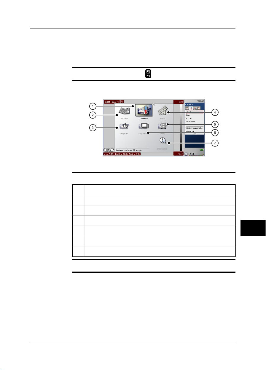
10 Screen elements
10.1 Mode selector
NOTE
Figure
Explanation
To go to the mode selector, push the button to the right of the joystick.
10732603;a3
This table gives an explanation to the figure above:
Camera mode: Analyze & save IR images.1
Archive mode: View saved images & video clip.2
Program mode: Save images automatically.3
Setup mode: Set up camera.4
Video mode: Record non-radiometric video clips.5
Sequence mode: Record radiometric IR sequences.6
10
Information mode: Camera information.7
Related topics
Publ. No. 1558550 Rev. a557 – ENGLISH (EN) – October 7, 2011 31
For locations of camera buttons, see section 9 – Camera parts on page 21.
Page 50

10 – Screen elements
10.2 Result table and measurement tools
10
NOTE
Figure
Explanation
To access the measurement tools, push the button.
10738803;a3
This table gives an explanation to the figure above:
Result table1
Line (measurement tool)2
Box (measurement tool)3
Circle (measurement tool)4
Status bar5
Temperature scale6
Isotherm (measurement tool)7
Spotmeter (measurement tool)8
32 Publ. No. 1558550 Rev. a557 – ENGLISH (EN) – October 7, 2011
Page 51

10.3 Toolbox, indicators and other objects
10 – Screen elements
Figure
Explanation
10738903;a2
This table gives an explanation to the figure above:
Mode indicator1
Image mode indicator2
Toolbox tabs3
Toolbox4
General information field5
SD Memory Card indicator (‘I’ or ‘II’). The indicator also shows the amount
6
of free space on the SD Memory Card.
As a warning, the indicator will turn yellow and then red as the amount of
free space decreases.
System time7
Power indicator (battery or mains supply)8
Battery capacity indicator9
System date10
Publ. No. 1558550 Rev. a557 – ENGLISH (EN) – October 7, 2011 33
10
Page 52

10 – Screen elements
10.4 Screen elements in infrared images
Explanation
This table explains the screen elements in infrared images (in Archive mode only):
Image description
Text annotation
Fusion
Voice annotation
Panorama
Image link (indicating associated panorama images)
10
34 Publ. No. 1558550 Rev. a557 – ENGLISH (EN) – October 7, 2011
Page 53

11 Connecting external devices
General
Related topics
You can connect the following external devices to the camera:
A power supply.
■
A video monitor.
■
A computer for recording infrared sequences at high speed.
■
A computer to move images and other files to and from the camera.
■
An external USB device, such as a USB keyboard, USB memory stick, USB-
■
Bluetooth microadapter (to connectto a headset),or a USB-WLAN micro adapter
(to connect the camera to a remote control (P/N T197230)).
A headset to record and listen to voice comments.
■
One or two SD Memory Cards.
■
WLAN card (Obsolete. A USB-WLAN micro adapter is the preferrred device to
■
use.)
Section 11.1 – Connecting devices to the rear connectors on page 36
■
Section 11.2 – Connecting devices to the front connector on page 38
■
Section 11.3 – Inserting SD Memory Cards on page 39
■
Publ. No. 1558550 Rev. a557 – ENGLISH (EN) – October 7, 2011 35
11
Page 54

11 – Connecting external devices
11.1 Connecting devices to the rear connectors
Figure
Explanation
10728503;a1
This table gives an explanation to the figure above:
To connect an external USB device to the camera, use a USB-A cable and
1
this connector. You can also plug in a USB memory stick in this connector,
or a USB-Bluetooth micro adapter. For WLAN connectivity to a remote
control (P/N T197230), use a USB-WLAN micro adapter.
To connect acomputer to the camera to move imagesand files to and from
11
Related topics
2
the camera, use a USB mini-B cable and this connector. This connector is
also used when pairing the camera to the remote control (P/N T197230).
To connect a computer for recording infrared sequences at high speed,
3
use a FireWire cable and this connector. You also move images and files
to and from the camera using a FireWire cable.
To connect a video monitor to the camera, use a CVBS cable (a composite
4
video cable) and this connector. When the lid to the connectors is closed,
you can get access to the connector by opening a rubber lid.
Section 25 – Finding the IP address for a camera connected using a FireWire cable
on page 159
36 Publ. No. 1558550 Rev. a557 – ENGLISH (EN) – October 7, 2011
Page 55

11 – Connecting external devices
Figure
Explanation
Related topics
10728603;a1
This table gives an explanation to the figure above:
To connect the power supply to the camera, use the power supply cable
1
and this connector. The power connector is protected by a rubber cover.
For informationabout pin configuration,see section 24– Technical data onpage 155.
Publ. No. 1558550 Rev. a557 – ENGLISH (EN) – October 7, 2011 37
11
Page 56

11 – Connecting external devices
11.2 Connecting devices to the front connector
Figure
Explanation
Related topics
10728703;a1
This table gives an explanation to the figure above:
To connect a headset to the camera, use the headset cable and this con-
1
nector.
For informationabout pin configuration,see section 24– Technical data onpage 155.
11
38 Publ. No. 1558550 Rev. a557 – ENGLISH (EN) – October 7, 2011
Page 57

11.3 Inserting SD Memory Cards
11 – Connecting external devices
Figure
Explanation
10728803;a1
This table gives an explanation to the figure above:
To insert an SD Memory Card (identified with Roman numeral ‘I’ in the
I
camera program), use this card slot.
To insert an SD Memory Card (identified with Roman numeral ‘II’ in the
II
camera program), use this card slot.
Formatting
memory cards
Publ. No. 1558550 Rev. a557 – ENGLISH (EN) – October 7, 2011 39
For best performance, memory cards should be formatted to the FAT (FAT16) file
system. Using FAT32-formatted memory cards may result in inferior performance.
To format a memory card to FAT (FAT16), follow this procedure:
Insert the SD Memory Card into a card reader that is connected to your
1
computer.
In Windows®Explorer, select My Computer and right-click the memory
2
card.
Select Format.3
Under File system, select FAT.4
11
Page 58

11 – Connecting external devices
Click Start.5
When you use one SD Memory Card only, always use the card slot marked “I”.
NOTE
■
This card slot has a higher file transfer rate than the card slot marked “II”.
SDHC Memory Cards that are 4 GB or larger can only be formatted to the FAT32
■
file system.
11
40 Publ. No. 1558550 Rev. a557 – ENGLISH (EN) – October 7, 2011
Page 59

12 Pairing Bluetooth devices
General
Procedure
Before youcan use a Bluetoothdevicewith the camera,youneed to pairthedevices.
Follow this procedure:
Insert a Bluetooth USB micro adapter into the USB connector.1
Turn on the camera.2
3
To go to the mode selector, push the button to the right of the joystick.
4
In the mode selector, select Setup and push the joystick.
In the toolbox, select Bluetooth.5
6
To search for a new device, select the icon.
Push the joystick.
7
At this stage, youneed to referto theuser documentation foryour Bluetooth
device.
Publ. No. 1558550 Rev. a557 – ENGLISH (EN) – October 7, 2011 41
12
Page 60

12 – Pairing Bluetooth devices
INTENTIONALLY LEFT BLANK
12
42 Publ. No. 1558550 Rev. a557 – ENGLISH (EN) – October 7, 2011
Page 61

13 Handling the camera
13.1 Charging the camera battery
13.1.1 Charging the battery using the power supply cable
You must charge the battery for four hours before starting the camera the first
NOTE
■
time. After that, youmust charge thebattery whenever awarning message for low
battery power is displayed on the screen.
The battery has a battery condition LED indicator. When the green LED glows
■
continuously, the battery is fully charged.
Procedure
Related topics
Follow this procedure to charge the battery using the power supply cable:
Connect the power supply cable plug to the connector on the battery.1
Connect the power supply wall plug to a mains supply.2
When the green LED of the battery condition indicator glows continuously,
3
disconnect the power supply cable.
For informationabout the batterycondition LED indicator, see section 9.4– Battery
■
condition LED indicator on page 27.
For information on how to install and remove the battery, see section 13.3.1 – In-
■
stalling the battery on page 48 and section 13.3.2 – Removing the battery on
page 49.
Publ. No. 1558550 Rev. a557 – ENGLISH (EN) – October 7, 2011 43
13
Page 62

13 – Handling the camera
13.1.2 Charging the battery using the stand-alone battery charger
You must charge the battery for four hours before starting the camera the first
NOTE
■
time. After that, youmust charge thebattery whenever awarning message for low
battery power is displayed on the screen.
The battery has a battery condition LED indicator. When the green LED glows
■
continuously, the battery is fully charged.
Procedure
Related topics
Follow this procedure to charge the battery using the stand-alone battery charger:
Put the battery in the stand-alone battery charger.1
Connect the power supply cable plug to the connector on the stand-alone
2
battery charger.
Connect the power supply wall plug to a mains supply.3
When the green LED of the battery condition indicator glows continuously,
4
disconnect the power supply cable.
For informationabout the batterycondition LED indicator, see section 9.4– Battery
■
condition LED indicator on page 27.
For information on how to install and remove the battery, see section 13.3.1 – In-
■
stalling the battery on page 48 and section 13.3.2 – Removing the battery on
page 49.
13
44 Publ. No. 1558550 Rev. a557 – ENGLISH (EN) – October 7, 2011
Page 63

13.2 Charging the remote control battery
13 – Handling the camera
NOTE
General
SEE
You must charge the battery for four hours before you start using the remote control
for the first time.
You must charge the battery when a low battery voltage warning is displayed on the
screen.
Follow one of these procedures to charge the battery:
Use the combined power supply and battery charger to charge the battery when
■
it is inside the remote control.
Use the combined power supply and battery charger to charge the battery when
■
it is outside the remote control.
For information on how to charge the battery, see the following sections:
Section 13.2.1 – Usingthe combined powersupply and battery charger tocharge
■
the battery when it is inside the remote control on page 46
Section 13.2.2 – Usingthe combined powersupply and battery charger tocharge
■
the battery when it is outside the remote control on page 47
Publ. No. 1558550 Rev. a557 – ENGLISH (EN) – October 7, 2011 45
13
Page 64

13 – Handling the camera
13.2.1 Using the combined power supply and battery charger to charge the battery when it is inside the remote control
NOTE
Procedure
For brevity, the ‘combined power supply and battery charger’ is called the ‘power
supply’ below.
Follow this procedure to use the power supply to charge the batterywhen it is inside
the remote control:
Open the battery compartment cover.1
Connect the power supply cable plug to the connector on the battery.2
Connect the power supply mains-electricity plug to a mains socket.3
Disconnect thepower supply cable plug whenthe green lightof the battery
4
condition indicator is continuous.
13
46 Publ. No. 1558550 Rev. a557 – ENGLISH (EN) – October 7, 2011
Page 65

13 – Handling the camera
13.2.2 Using the combined power supply and battery charger to charge the battery when it is outside the remote control
NOTE
Procedure
For brevity, the ‘combined power supply and battery charger’ is called the ‘power
supply’ below.
Follow thisprocedure to usethe powersupply to chargethe battery when it isoutside
the remote control:
Put the battery on a flat surface.1
Connect the power supply cable plug to the connector on the battery.2
Connect the power supply mains-electricity plug to a mains socket.3
Disconnect thepower supply cable plug whenthe green lightof the battery
4
condition indicator is continuous.
Publ. No. 1558550 Rev. a557 – ENGLISH (EN) – October 7, 2011 47
13
Page 66

13 – Handling the camera
13.3 Installing and removing the camera battery
13.3.1 Installing the battery
NOTE
Procedure
Use a clean and dry cloth to removeany water or moisture on the battery before you
install it.
Follow this procedure to install the battery:
Align the battery with the battery slot.
1
10728903;a2
Push the battery intoposition until the battery lockingmechanism engages.
2
10729003;a2
13
48 Publ. No. 1558550 Rev. a557 – ENGLISH (EN) – October 7, 2011
Page 67

13.3.2 Removing the battery
13 – Handling the camera
Procedure
Follow this procedure to remove the battery:
Turn the camera grip counter-clockwise to access the release button for
1
the battery locking mechanism.
10729303;a1
Push the release button for the battery locking mechanism up.
2
10729103;a1
Pull out the battery from the battery holder.
3
10729203;a2
Publ. No. 1558550 Rev. a557 – ENGLISH (EN) – October 7, 2011 49
13
Page 68

13 – Handling the camera
13.4 Installing and removing the remote control battery
13.4.1 Installing the remote control battery
NOTE
Procedure
Use a clean, drycloth to removeany water ormoisture on the battery beforeyou insert
it.
Follow this procedure to install the battery:
Push the release button on the battery compartment cover to unlock it.
1
10759603;a1
Open the cover to the battery compartment.
2
10759703;a1
Push the battery into the battery compartment until the battery locking
3
mechanism engages.
10759803;a1
13
50 Publ. No. 1558550 Rev. a557 – ENGLISH (EN) – October 7, 2011
Page 69

Close the cover to the battery compartment.
4
10759903;a1
13 – Handling the camera
Publ. No. 1558550 Rev. a557 – ENGLISH (EN) – October 7, 2011 51
13
Page 70

13 – Handling the camera
13.4.2 Removing the remote control battery
Procedure
Follow this procedure to remove the battery:
Push the release button on the battery compartment cover to unlock it.
1
10759603;a1
Open the cover to the battery compartment.
2
10763903;a1
Push the red release button in the direction of the arrow to unlock the bat-
3
tery.
10760003;a2
13
52 Publ. No. 1558550 Rev. a557 – ENGLISH (EN) – October 7, 2011
Page 71

Pull out the battery from the battery compartment.
4
10760103;a1
13 – Handling the camera
Publ. No. 1558550 Rev. a557 – ENGLISH (EN) – October 7, 2011 53
13
Page 72

13 – Handling the camera
13.5 Turning on the camera
Procedure
Related topics
To turn on the camera, push and release the button.
For locations of camera buttons, see section 9 – Camera parts on page 21.
13.6 Turning off the camera
Procedure
Related topics
To turn off thecamera, push and holdthe button formore than two seconds.
■
To display adialog box whereyou can chooseto put thecamera in standby mode,
■
briefly push the button. This dialog box will disappear in 10 seconds.
For locations of camera buttons, see section 9 – Camera parts on page 21.
13.7 Setting power save mode
Procedure
NOTE
Related topics
When the camera ison, push and release theOn/Off button toset power save mode.
If you do not use the camera, the camera will enter power save mode after a time
period that you can set in the menu system. After several hours in power save mode
the camera power turns off.
For locations of camera buttons, see section 9 – Camera parts on page 21.
■
For information about setting power save mode, see section 22.3.7 – Changing
■
settings for power management on page 142.
13
54 Publ. No. 1558550 Rev. a557 – ENGLISH (EN) – October 7, 2011
Page 73

13.8 Adjusting the viewfinder eyepiece
13 – Handling the camera
General
Procedure
You can adjust the viewfinder eyepiece for your left or right eye.
Follow this procedure to adjust the viewfinder eyepiece:
Pull the rubber eyepiece.
1
10739203;a1
Rotate the rubber eyepiece 180°.
2
10739303;a1
Push the rubber eyepiece back into position.
3
10739403;a1
Publ. No. 1558550 Rev. a557 – ENGLISH (EN) – October 7, 2011 55
13
Page 74

13 – Handling the camera
13.9 Adjusting the viewing angle of the viewfinder
General
Figure
Procedure
To make your working position as comfortable as possible, you can adjust the
viewing angle of the viewfinder.
10729403;a1
To adjust the viewfinder, tilt the viewfinder up or down.
13
56 Publ. No. 1558550 Rev. a557 – ENGLISH (EN) – October 7, 2011
Page 75

13 – Handling the camera
13.10 Adjusting the viewfinder’s dioptric correction
General
Figure
Procedure
NOTE
The viewfinder’s dioptric correction can be adjusted for your eyesight.
10729503;a1
To adjust the viewfinder’s dioptric correction, look at the displayed text or graphics
on the screen and rotate the adjustment knob clockwise or counter-clockwise for
best sharpness.
Maximum dioptric correction: +2
■
Minimum dioptric correction: –2
■
Publ. No. 1558550 Rev. a557 – ENGLISH (EN) – October 7, 2011 57
13
Page 76

13 – Handling the camera
13.11 Adjusting the camera grip
General
Figure
Procedure
To make your working position as comfortable as possible, you can adjust the angle
of the camera grip.
10729603;a1
To adjust the camera grip, rotate the camera grip clockwise or counter-clockwise.
13
58 Publ. No. 1558550 Rev. a557 – ENGLISH (EN) – October 7, 2011
Page 77

13.12 Opening the display
13 – Handling the camera
Procedure
Follow this procedure to open the display:
Push the display release button up.
1
10729703;a1
Open the display.
2
10729803;a2
NOTE
The viewfinder will automaticallyturn off when you open the display. You can change
this behavior by modifying the display settings.
Related topics
Publ. No. 1558550 Rev. a557 – ENGLISH (EN) – October 7, 2011 59
Section 22.3.8 – Changing settings for the LCD display on page 143
13
Page 78

13 – Handling the camera
13.13 Adjusting the viewing angle of the display
General
Figure
To make your working position as comfortable as possible, you can adjust the
viewing angle of the display.
10729903;a1
Procedure
To adjust the viewing angle of the display, rotate the display clockwise or counterclockwise.
13
60 Publ. No. 1558550 Rev. a557 – ENGLISH (EN) – October 7, 2011
Page 79

13.14 Installing an infrared lens
Do not touch the lens surface when you install an infrared lens. If this happens,
NOTE
■
clean the lens according to the instructions in section 23.2 – Infrared lens on
page 152.
13 – Handling the camera
Procedure
Follow this procedure to install an infrared lens:
Align the index mark on the lens with the index mark on the bayonet ring.
1
10730403;a1
Carefully push the infrared lens into the bayonet ring.
2
10730503;a1
Rotate the infrared lens 30° clockwise (looking at the front of the lens).
3
10730603;a1
Publ. No. 1558550 Rev. a557 – ENGLISH (EN) – October 7, 2011 61
13
Page 80

13 – Handling the camera
13.15 Removing an infrared lens
Do not touch the lens surface when you remove an infrared lens. If this happens,
NOTE
■
clean the lens according to the instructions in section 23.2 – Infrared lens on
page 152.
When you have removed the lens, put the lens caps on the lens to protect it from
■
dust and fingerprints.
Procedure
Follow this procedure to remove an infrared lens:
Push the release button for the infrared lens forward.
1
10739103;a1
Rotate the infrared lens counter-clockwise 30° (looking at the front of the
2
lens).
10730703;a1
Carefully pull out the infrared lens from the bayonet ring.
3
10730803;a1
13
62 Publ. No. 1558550 Rev. a557 – ENGLISH (EN) – October 7, 2011
Page 81

13 – Handling the camera
13.16 Adjusting the infrared camera focus manually
NOTE
Figure
Procedure
Do not touch the lens surface when you adjust the infrared camera focus manually.
If this happens, clean the lens according to the instructions in section 23.2 – Infrared
lens on page 152.
10730003;a1
Do one of the following:
For far focus, rotate the focus ring counter-clockwise (looking at the front of the
■
lens)
For near focus, rotate the focus ring clock-wise (looking at the front of the lens)
■
Publ. No. 1558550 Rev. a557 – ENGLISH (EN) – October 7, 2011 63
13
Page 82

13 – Handling the camera
13.17 Adjusting the infrared camera focus
Procedure
Related topics
Follow this procedure to adjust the infrared camera focus:
Make sure that the image is in live mode.1
2
To adjust the camera focus, push the button left/right.
For locations of camera buttons, see section 9 – Camera parts on page 21.
13
64 Publ. No. 1558550 Rev. a557 – ENGLISH (EN) – October 7, 2011
Page 83

13.18 Autofocusing the infrared camera
13 – Handling the camera
Procedure
Related topics
Follow this procedure to autofocus the infrared camera:
Make sure that the image is in live mode.1
2
To autofocus the camera, push the center of the button.
For locations of camera buttons, see section 9 – Camera parts on page 21.
■
For information on how to adjust the infrared camera focus, see section 13.16 –
■
Adjusting the infrared camera focus manually on page 63.
You can also continuously autofocus the infrared camera using the laser pointer.
■
For more information, see section 22.3.5 – Changing settings for the laser on
page 140.
Publ. No. 1558550 Rev. a557 – ENGLISH (EN) – October 7, 2011 65
13
Page 84

13 – Handling the camera
13.19 Autofocusing the digital camera
General
Procedure
Related topics
You automatically autofocusthe digital camerawhen you autofocusthe infrared image.
To autofocus the digital camera when you are in visual mode, push the center of the
button.
For locations of camera buttons, see section 9 – Camera parts on page 21.
13
66 Publ. No. 1558550 Rev. a557 – ENGLISH (EN) – October 7, 2011
Page 85

13.20 Operating the laser pointer
13 – Handling the camera
Figure
Procedure
NOTE
Related topics
10730303;a1
Follow this procedure to operate the laser pointer:
To turn on the laser pointer, push and hold the laser button.1
To turn off the laser pointer, release the laser button.2
The laser pointer may not be enabled in all markets.
■
An indicator on the screen shows the position of the laser dot.
■
Section 9.6 – Laser pointer on page 29
■
Section 22.3.5 – Changing settings for the laser on page 140
■
Publ. No. 1558550 Rev. a557 – ENGLISH (EN) – October 7, 2011 67
13
Page 86

13 – Handling the camera
INTENTIONALLY LEFT BLANK
13
68 Publ. No. 1558550 Rev. a557 – ENGLISH (EN) – October 7, 2011
Page 87

14 Working with views and images
14.1 Previewing an image
General
Procedure
NOTE
Related topics
You can preview an infrared image or digital photo before you save it to an SD
Memory Card. This enablesyou to seeif theimage or photocontains the information
you want before you save it.
In preview mode, you can also manipulate the image before you save it.
To preview an image, push and release the Preview/Save button.
You can also preview an infrared image and a digital photo at the same time. For
more information, see section 22.2.2 – Changing settings for image saving on
page 134.
For locations of camera buttons, see section 9 – Camera parts on page 21.
Publ. No. 1558550 Rev. a557 – ENGLISH (EN) – October 7, 2011 69
14
Page 88

14 – Working with views and images
14.2 Saving an image
General
Naming
convention
Image capacity
Procedure
NOTE
Related topics
You can save one image or many images to an SD Memory Card.
You can specify the naming convention you want to use for the image you save. For
more information, see section 22.2.2 – Changing settings for image saving on
page 134.
This table gives information on theapproximate number of images that can be saved
on SD Memory Cards:
No voice annotationCard size
To save an image fromlive or preview mode, push and hold the Preview/Savebutton
for more than one second.
You can specify the folder to use when saving an image by specifying a default work
folder. For more information, see section 14.14 – Specifying work folder on page 86.
For locations of camera buttons, see section 9 – Camera parts on page 21.
■
For information on how to change settings for image saving, see section 22.2.2
■
– Changing settings for image saving on page 134.
For information on how to specify default work folder, see section 14.14 – Speci-
■
fying work folder on page 86.
30 seconds voice annotation
250500256 MB
5001000512 MB
100020001 GB
14
70 Publ. No. 1558550 Rev. a557 – ENGLISH (EN) – October 7, 2011
Page 89

14.3 Opening an image
14 – Working with views and images
General
Procedure
Related topics
When you save an image, you store the image on an SD Memory Card. To display
the image again, you can open it from the SD Memory Card.
Follow this procedure to open an image:
1
To go to the mode selector, push the button to the right of the joystick.
2
In the Mode selector, select Archive and push the joystick.
Do one of the following:
3
To select a different image, move the joystick left/right.
■
To see an overview of all images, push the Focus button and do the
■
following:
1 To select the image you want to open, move the joystick left/right or
up/down.
2 To select Single image view, move the joystick up/down.
3 Push the joystick.
For locations of camera buttons, see section 9 – Camera parts on page 21.
Publ. No. 1558550 Rev. a557 – ENGLISH (EN) – October 7, 2011 71
14
Page 90

14 – Working with views and images
14.4 Using the zoom function
General
Procedure
NOTE
Related topics
You can zoom in on infrared images. This enables you to view details in an image.
Do one of the following:
If the image is in live mode, select Zoom/Pan in the toolbox and push the joystick
■
up/down to adjust zoom.
If the image is in preview mode, push the Focus button left/right. You can also
■
select Zoom/Pan in the toolbox and push the joystick up/down to adjust zoom.
When you save the image again, the zoom factor will be saved too. To save the
■
image, push the Preview/Save button.
You can zoom out on images that you have saved by using PC software from
■
FLIR Systems.
To cancel the zoom function, push the button.
■
For locations of camera buttons, see section 9 – Camera parts on page 21.
14
72 Publ. No. 1558550 Rev. a557 – ENGLISH (EN) – October 7, 2011
Page 91

14.5 Using the Panorama function
14 – Working with views and images
General
NOTE
Procedure
The camera has a Panorama function. Thismeans thatyou can create larger images
by stitching normal images together.
The images are storedin the camerausing a special mode. Theactual stitching takes
place in FLIR Systems PC software for post-processing, for example FLIR Reporter.
When you enter this mode, all graphics are removed from the screen.
■
In thumbnail view, the images that are createdusing this function display the icon
■
.
To create a Panorama image, follow this procedure:
1
To go to the mode selector, push the button to the right of the joystick.
2
In the mode selector, select Camera and push the joystick.
Go to the right-most tab (Application), using the joystick.3
Push the joystick. This will display the following screen:
4
T630356;a1
The screen is divided into nine areas using four guidelines. In the tools
pane, a red rectangle indicates which section of the screen you will save
when saving an image.
Note that the guidelines are only intended as an aid when you move the
camera to the next area for which you want to save an image. Thus, the
guidelines make it easy for you to align the images.
Publ. No. 1558550 Rev. a557 – ENGLISH (EN) – October 7, 2011 73
14
Page 92

14 – Working with views and images
To save an image, push the Preview/Save button.
5
The saved image will now be displayed in the corresponding area in the
tools pane. You can also see that the left-most area on the screen shows
the image you just saved (indicated here in red):
T630357;a1
Using the joystick, you can now decide in which area you want to save the
6
next image, and then save the image by pushing the Preview/Save button.
Continue with this procedure until you have created a complete image.
7
To finish and leave this mode, push the button.
14
Related topics
For locations of camera buttons, see section 9 – Camera parts on page 21.
74 Publ. No. 1558550 Rev. a557 – ENGLISH (EN) – October 7, 2011
Page 93

14.6 Using the pan function
14 – Working with views and images
General
Procedure
NOTE
Related topics
When you have zoomed into an image, you can pan over the image. This enables
you to specify the area of interest before you save the image again.
Follow this procedure to use the pan function:
When the image is in preview mode or archive mode, select Zoom/Pan in
1
the toolbox.
Push the joystick to go to pan mode.2
To pan over the image, push the joystick left/right or up/down.3
When you save the image again, the pan factor will be saved too.
For locations of camera buttons, see section 9 – Camera parts on page 21.
Publ. No. 1558550 Rev. a557 – ENGLISH (EN) – October 7, 2011 75
14
Page 94

14 – Working with views and images
14.7 Adjusting an image
General
Example 1
An image can be adjusted automatically or manually.
These two modes are indicated in the top right corner of the screen by the words
Auto and Manual. You use the Auto/Manual button to switch between these two
modes
This figure shows two infrared images of cable connection points. In the left image
a correct analysis of the left cable is difficult to do if you only auto-adjust the image.
You can analyze the left cable in more detail if you
change the temperature scale level;
■
change the temperature scale span.
■
In the image to the left, the image is auto-adjusted. In the right image the maximum
and minimum temperature levels have been changed to temperature levels near the
object. On the temperature scale to the right of each image you can see how the
temperature levels were changed.
10577503;a2
14
76 Publ. No. 1558550 Rev. a557 – ENGLISH (EN) – October 7, 2011
Page 95

14 – Working with views and images
Example 2
This figure shows two infrared images of an isolator in a power line.
In the image to the left the cold sky and the power line structure are recorded at a
minimum temperature of –26.0°C (–14.8°F). In the right image the maximum and
minimum temperature levels have been changed to temperature levels near the isolator. This makes it easier to analyze the temperature variations in the isolator.
10742503;a3
Publ. No. 1558550 Rev. a557 – ENGLISH (EN) – October 7, 2011 77
14
Page 96

14 – Working with views and images
Changing
temperature scale
level
Changing
temperature scale
span
Related topics
Follow this procedure to change the temperature scale level:
1
To go to the mode selector, push the button to the right of the joystick.
2
In the mode selector, select Camera and push the joystick.
Do one of the following:
3
In the toolbox, select Level/Span
■
Push A/M to go to manual mode
■
To change the temperature scale level, move the joystick up/down.4
Follow this procedure to change the temperature scale span:
1
To go to the mode selector, push the button to the right of the joystick.
2
In the mode selector, select Camera and push the joystick.
Do one of the following:
3
In the toolbox, select Level/Span
■
Push A/M to go to manual mode
■
To change the temperature scale span, move the joystick left/right.4
For locations of camera buttons, see section 9 – Camera parts on page 21.
14
78 Publ. No. 1558550 Rev. a557 – ENGLISH (EN) – October 7, 2011
Page 97

14 – Working with views and images
14.8 Changing maximum and minimum scale values
General
Typical examples
Procedure
You can change the maximum and minimum scale values on the temperature scale.
A typical application when you want to change the maximum scale value:
You are inspecting an object that is located in front of a background that has a a
considerably higher temperature—e.g. an object in a very hot furnace. In this case
you want to use as many colors as possible for your object and as few as possible
for the background. To do this, specify a temperature slightly above the temperature
you can expect for your object.
A typical application when you want to change the minimum scale value:
You are inspecting an object that is located in front of a background that has a considerably lower temperature—e.g. power lines in front of a clearsky. In this case you
want to use as many colors as possible for your object and as few as possible for
the background. To do this, specify a temperature slightly below the temperature
you can expect for your object.
Follow this procedure to set the maximum and minimum scale values:
1
To go to the mode selector, push the button to the right of the joystick.
2
In the mode selector, select Camera and push the joystick.
In the toolbox, select Max./Min. and push the joystick.3
Do one of the following and push the joystick to confirm each choice:
4
To change the maximum scale value, move the joystick up/down.
■
To change the minimum scale value, move the joystick left/right.
■
To auto-adjust the image one time, push the joystick.
■
5
To confirm and leave the dialog box, push the button.
Related topics
Publ. No. 1558550 Rev. a557 – ENGLISH (EN) – October 7, 2011 79
For locations of camera buttons, see section 9 – Camera parts on page 21.
14
Page 98

14 – Working with views and images
14.9 Hiding overlay graphics
General
Procedure
NOTE
Related topics
Overlay graphics provide information about an image. You can choose to hide all
overlay graphics.
1
To go to the mode selector, push the button to the right of the joystick.
2
In the mode selector, select Camera and push the joystick.
To hide overlay graphics, select Hide graphics in the toolbox.3
If you want to display or hide only some individual graphics, you can do so in Setup
mode.
For locations of camera buttons, see section 9 – Camera parts on page 21.
14
80 Publ. No. 1558550 Rev. a557 – ENGLISH (EN) – October 7, 2011
Page 99

14.10 Changing the palette
14 – Working with views and images
General
Procedure
Related topics
You can change the color palette that the camera uses to display different temperatures. A different palette can make it easier to analyze an image.
Follow this procedure to change the palette:
1
To go to the mode selector, push the button to the right of the joystick.
2
In the mode selector, select Camera and push the joystick.
In the toolbox, select Palette and push the joystick.3
Do one of the following and push the joystick to confirm each choice:
4
To select a new palette, movethe joystick up/down to select the palette.
■
To invert theinvert the palette, move thejoystick up/down to select Invert
■
palette.
To enable or disable saturation colors, select Saturation colors and
■
push the joystick, then move the joystick up/down. When saturations
colors are enabled, the areas that contain temperatures outside the
present level/span settings are colored with the saturation colors. The
saturation colors contain an ‘overflow’ color and an ‘underflow’ color.
5
To confirm and leave the dialog box, push the button.
For locations of camera buttons, see section 9 – Camera parts on page 21.
Publ. No. 1558550 Rev. a557 – ENGLISH (EN) – October 7, 2011 81
14
Page 100

14 – Working with views and images
14.11 Associating images
General
Why associate
images?
Procedure
Association of images is, under normal circumstances, automatic.
For example,if you setup thecamera to savea digital photo after yousave an infrared
image, the digital photo is automatically associated with the infrared image.
In some situations, you may want to manually associate one image with another im-
age.
Associating images simplifies post-processing and reporting in, for example, FLIR
Reporter.
Follow this procedure to associate one image with another image:
1
To go to the mode selector, push the button to the right of the joystick.
2
In the Mode selector, select Archive and push the joystick.
To see an overview of all images, push the Focus button.3
To go to the image you want to associate with another image, move the
4
joystick left/right or up/down.
To mark the image, push the Preview/Save button.5
To go to the other image, move the joystick left/right or up/down.6
To mark the image, push the Preview/Save button.7
To display a menu, push the joystick.8
To associate the images, select Associate images on the menu and push
9
the joystick.
Related topics
For locations of camera buttons, see section 9 – Camera parts on page 21.
14
82 Publ. No. 1558550 Rev. a557 – ENGLISH (EN) – October 7, 2011
 Loading...