

Page 1
flir.com/security/pro
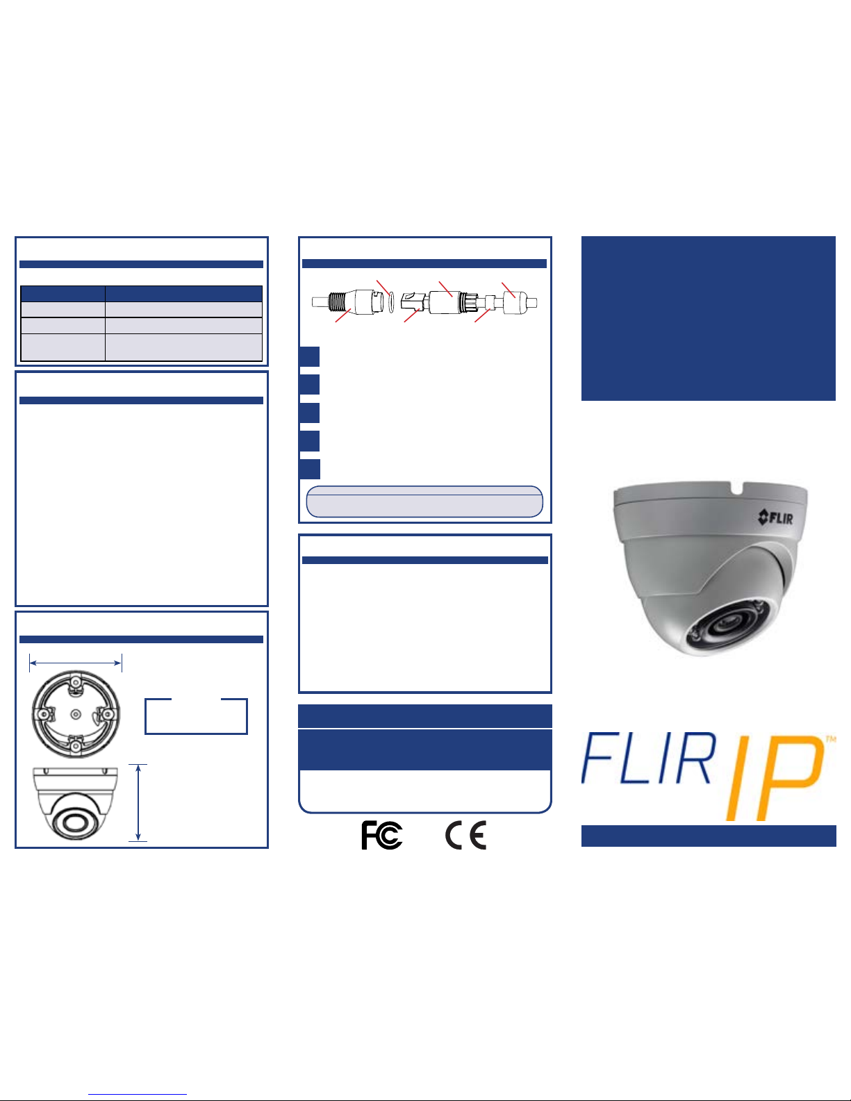
Cap housing
RJ45 plug
Outer seal
Inner
seal
Cap-sealing nut
Ethernet
connector
QUICK START GUIDE
English Version 1.0
FLIR Systems, Inc., Copyright © 2017
As our products are subject to continuous improvement, FLIR Systems
Inc. reserves the right to modify product design, specifications and
prices, without notice and without incurring any obligation. E&OE
flir.com/security/pro
VISIT
Compatible Accessories
IT’S ALL ON THE WEB!
FCC Notice
This equipment has been tested and found to comply with
the limits for a Class A digital device, pursuant to Part
15 of the FCC Rules. These limits are designed to provide
reasonable protection against harmful interference when
the equipment is operated in a commercial environment. This
equipment generates, uses, and can radiate radio frequency
energy and, if not installed and used in accordance with the
instruction manual, may cause harmful interference to radio
communications. Operation of this equipment in a residential
area is likely to cause harmful interference in which case the
user will be required to correct the interference at his own
expense.
P143E4_QSG_EN_R1
This security camera has several mounting options:
Safety Precautions
• Use an appropriate low-voltage power cable to
prevent fire or electrical shock.
• Make sure to install the camera in an area that can
support the camera weight.
• There are no user-serviceable parts inside the
camera. Please do not disassemble the camera.
• Do not clean the lens cover with an abrasive
cleaning materials. Please use a soft cloth to clean
the lens cover.
• Camera is rated for outdoor use (IP66), but is not
intended for submersion in water.
• Extend the Ethernet-cable run for your camera
up to 300ft. You can use an RJ45 coupler or
network switch to connect male ends of Ethernet
cable together. A maximum of 3 connections is
recommended.
Weights & Dimensions
3.7" / 93mm
3.2"
80mm
0.7lbs / 0.35kg
Weight
Accessories Model Numbers
Junction Boxes S1JF2G or S4JF1G
Wall Mount S1WA1G
Pole Mounts S4PA2G with S1WA1G, or
S4PA2G with S1JF2G
Using the RJ45 Cap (Optional)
ATTENTION:
The supplied RJ45 cap is weather-resistant. Seal the cap with
silicone if it will be exposed to precipitation regularly.
1
2
3
4
Fit the outer seal over your camera’s Ethernet connector
and insert the inner seal into the cap housing.
Run the stripped end of an Ethernet cable through the
parts of the RJ45 cap, as shown above.
Terminate the Ethernet cable with an RJ45 plug, and plug
the cable into your camera’s Ethernet connector.
5
Screw the cap housing onto the Ethernet connector.
Screw the cap-sealing nut tightly into the cap
housing.
4MP HD IP
Eyeball Dome Camera
MODEL:
P143E4 SERIES
Page 2
Package Contents
• 4MP HD IP Eyeball Dome Camera
• Mounting Kit
• Quick Start Guides
Rotate the camera base counter-clockwise to separate
it from the ball camera, adjustment ring, and dome cover.
Connecting the Camera
ATTENTION:
Test the camera(s) prior to selecting a permanent mounting location
by temporarily connecting the camera(s) and cables to an NVR or
PoE network switch.
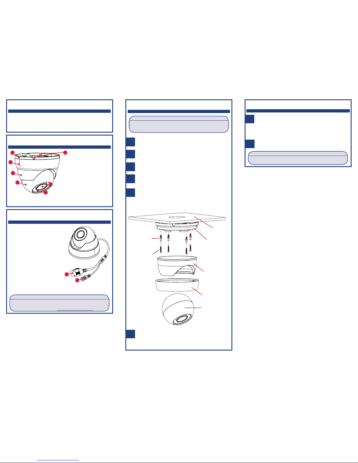
Installing the Camera
1
Use the included mounting template to mark and drill
holes for the included mounting screws.
2
3
4
5
6
Feed the camera cables through the camera base.
Connect the video and camera cable as shown in the
section “Connecting the Camera”.
Mount the camera base to the mounting surface using
the included mounting screws.
Place the adjustment ring over the dome cover, then
place both over the ball camera. Twist the adjustment
ring clockwise to secure the components in place. Do not
tighten all the way.
NOTE: Use the included drywall anchors if installing on a
drywall surface.
B. Power Input: If not using PoE,
connect the camera to a 12V DC power source. See power
requirement specification in datasheet.
A
B
A. Ethernet Port (PoE):
Connect the camera to an NVR
or a router or switch on your
network using Cat5e or better
Ethernet cable (not included).
PoE Class 3 supported.
NOTE: For instructions on
weatherproofing the Ethernet
connection, see “Using the
RJ45 Cap” on the back of this
guide.
Camera Overview
A. Camera Base
B. Adjustment Ring
C. Camera Cover
D. Ball Camera
E. Cable Notches (4×)
F. Camera Lens
G. Light Sensor and IR
LEDs
A
B
C
D
F
G
E
Installing the Camera (cont’d)
7
Move the ball camera to the desired position. While
holding the ball camera firmly in place, twist the
adjustment ring the rest of the way to secure it to
the camera base. Holding the camera prevents it from
moving while securing the adjustment ring.
ATTENTION:
Make sure IR LEDs are not blocked by the dome cover to prevent IR
reflection.
8
Remove the vinyl film from the camera lens once
installation is complete.
Mounting
surface
Camera base
Drywall
anchors (4×)
Mounting
screws (4×)
Camera cover
Ball camera
Adjustment
ring
ATTENTION:
You must connect the camera to a supporting H.265 NVR to take
advantage of H.265 compression. For more information, see your IP
camera’s instruction manual on www.flir.com/security/pro.
 Loading...