

FLIR Nexus Configuration Manual

Nexus IP Camera
Configuration Guide

© 2013 FLIR Systems, Inc. All rights reserved worldwide. No parts of this manual, in whole or in part, may be
copied, photocopied, translated, or transmitted to any electronic medium or machine readable form without the
prior written permission of FLIR Systems, Inc.
Names and marks appearing on the products herein are either registered trademarks or trademarks of FLIR
Systems, Inc. and/or its subsidiaries. All other trademarks, trade names, or company names referenced herein are
used for identification only and are the property of their respective owners.
This product is protected by patents, design patents, patents pending, or design patents pending.
The contents of this document are subject to change.
FLIR Systems, Inc.
70 Castilian Drive
Goleta, CA 93117
Phone: 888.747.FLIR (888.747.3547)
International: +1.805.964.9797
http://www.flir.com
Document History
Version Date Coment
100 Jan 2012 Initial Rele ase
110 Jun 2013 New web interface (3.0), WW 1.4 release
427-0030-00-28 Version 110 Jun 2013 -ii

Table of Contents
Ta b l e o f C on te nt s
Nexus IP Camera Configuration
1.1 Introduction ...............................................................................................................1-1
1.2 Nexus IP Camera ......................................................................................................1-2
1.3 Nexus Server Configuration ......................................................................................1-2
1.3.1 Serial and/or IP Communications ..................................................................... 1-2
1.3.2 Serial Communications .................................................................................... 1-3
1.4 System Information Displayed at Startup .................................................................. 1-4
1.5 FLIR Certified Systems Integrator (FCSI) Training .................................................... 1-4
Basic Operation and Configuration
2.1 Power and analog video ...........................................................................................2-1
2.2 Basic Test and Configuration Steps .......................................................................... 2-2
2.3 Camera Bench Test ..................................................................................................2-2
2.4 Web Browser Interface ............................................................................................. 2-3
2.4.1 Camera Control and Status ..............................................................................2-4
2.4.2 Web Control Panel ...........................................................................................2-5
2.4.3 Help .................................................................................................................2-8
2.4.4 Log Off ............................................................................................................. 2-8
2.5 Thermal Imaging Overview .......................................................................................2-9
2.6 Basic Camera Configuration ................................................................................... 2-10
2.7 Expert and Admin Logins ........................................................................................ 2-10
2.7.1 Maintenance Menu ........................................................................................2-11
2.8 Troubleshooting Tips ..............................................................................................2-17
2.8.1 Image freezes momentarily ............................................................................2-17
2.8.2 No video ........................................................................................................2-17
2.8.3 Performance varies with time of day ..............................................................2-17
2.8.4 Unable To Communicate Over Ethernet ........................................................ 2-18
2.8.5 Unable to control the camera .........................................................................2-19
2.8.6 General Errors ...............................................................................................2-20
2.8.7 Unable to View Video Stream ........................................................................2-20
2.8.8 Noisy image ................................................................................................... 2-21
2.8.9 Image too dark or too light ..............................................................................2-21
2.8.10 Eastern or Western Exposure ......................................................................2-22
2.9 Setting the IP address on a Windows PC ................................................................ 2-23
Advanced Configuration
3.1 Thermal Image Setup ...............................................................................................3-1
3.1.1 ROI .................................................................................................................. 3-2
3.1.2 AGC .................................................................................................................3-2
3.1.3 Scene Presets .................................................................................................3-2
3.1.4 Digital Detail Enhancement (DDE) ................................................................... 3-2
3.1.5 Flat Field Correction (FFC) ..............................................................................3-3
3.1.6 Save Settings ................................................................................................... 3-3
3.2 Surveillance (Auto Scan / Scan List) .........................................................................3-3
3.2.1 Auto Scan ........................................................................................................3-3
3.2.2 Scan List .......................................................................................................... 3-3
427-0030-00-28 Version 110 Jun 2013 iii

Table of Contents
3.3 Maintenance Mode ................................................................................................... 3-4
3.3.1 Configuration Changes That Require Restart ..................................................3-4
3.4 Restarting the Server ................................................................................................3-4
3.5 Serial Communications (Serial Remote) ...................................................................3-6
3.5.1 AutoPan Function ............................................................................................3-9
3.5.2 Serial Extensions ...........................................................................................3-10
3.5.3 Preset Map File ..............................................................................................3-10
3.6 Remote/VMS (ONVIF Interface) .............................................................................3-11
3.7 On Screen Display (OSD) .......................................................................................3-12
3.8 Video Stream Parameters ....................................................................................... 3-13
3.8.1 RTP Settings .................................................................................................. 3-14
3.8.2 Network Options (Unicast/Multicast) ..............................................................3-14
3.8.3 Settings .......................................................................................................... 3-15
3.8.4 MJPEG Codec Type ......................................................................................3-16
3.9 Configuration File ....................................................................................................3-17
3.10 Restoring the Factory Settings ..............................................................................3-18
427-0030-00-28 Version 110 Jun 2013 iv

1 Nexus IP Camera Configuration
FLIR IP cameras use a client/server communication architecture knows as Nexus. This manual provides
a brief guide to configuration of FLIR Nexus IP cameras. If you need help during the installation and
configuration process, contact your local FLIR representative or, call 877-773-3547 inside the US.
For specific information about how to mount and connect a FLIR thermal camera, refer to the installation
manual provided with the camera.
This document includes the following topics:
• Configuration overview
• Web Configuration Tool
• Bench testing the camera
• Troubleshooting Tips
• Basic configuration of the server
Refer to the FLIR Sensors Manager User Manual (FLIR Pub. No. T559777) for detailed information
about how to use the FLIR Sensors Manager (FSM) client to operate a camera, view video, and so on.
For cameras that do not have Nexus built-in, a JPC3G1 server or a Microsoft Windows-based PC server
can be used to provide Nexus capabilities. The JPC3G server acts as a video encoder and primary
interconnection junction box - it provides an IP connection for analog cameras and other devices.
Similarly, a PC running Windows can be used as a Nexus Server, and it can be used to integrate other
sensors and devices with the FLIR cameras. For configuration information regarding these Nexus
Servers, contact FLIR Technical Support.
1.1 Introduction
A FLIR IP Camera with Nexus2 can operate as both an analog camera and an IP camera. When used as
an IP camera, the camera can be configured with a web browser by accessing the Web Configuration
Tool, and this guide provides information about how to use that web tool. The latest release of the web
tool also allows the user to view video and to operate the camera (for example, to zoom in or out). In
addition, the camera can be operated using the FSM client, and this manual provides a brief introduction
to using FSM to perform a bench test of the camera.
The FLIR Nexus IP Cameras have microprocessors that run a software process called the Nexus Server.
The Nexus Server software controls the devices such as thermal and daylight cameras, pan/tilt platforms
and so on, and communicates across the TCP/IP network with command and control clients such as
FLIR Sensors Manager (FSM) or another Video Management System (VMS).
The configuration interface for various types of Nexus IP cameras is similar in many respects, regardless
of the camera model. In this manual, each Nexus IP camera may be referred to as a “Nexus Server”, or
simply as a “server”, and, in a more general sense, it may be referred to as a camera. In some cases it
may also be referred to as a “sensor”. Specific sections are included in the manual to point out when
there are configuration differences between the various IP camera models.
The video from the camera can be viewed over a traditional analog video network, and it can be viewed
by streaming it over an IP network. Analog video requires a connection to a video monitor or an analog
matrix/switch. For IP video streams, the cameras provide a choice of MPEG-4, M-JPEG or H.264 video
1. The JPC3G is the third generation of the Junction Protocol Converter (JPC) controller.
2. At the time of publication, this includes the following types of FLIR thermal cameras: DSeries, F-Series, FC-Series, PT-Series, and A310pt Series.
427-0030-00-28 Version 110 Jun 2013 1-1

1
Nexus IP Camera Configuration
encoding. The IP video will require a connection to an Ethernet network switch, and a computer with
the appropriate software (such as FSM or a web browser) for viewing the video.
Some Nexus Servers can be controlled through either serial or IP communications. For some
cameras that use serial communications, those settings may be configured using hardware DIP
switches rather than software settings. If available, the configuration of serial communications
parameters using hardware DIP switches is described in the installation manual for the camera, rather
than this document.
1.2 Nexus IP Camera
When a camera has Nexus capabilities, that means there is a microprocessor inside that runs the
Nexus Server software. The Nexus Server provides a number of services, including camera control,
video streaming, and geo-referencing capabilities. The Nexus communications protocol is an open,
standards-based protocol that allows the server to communicate with a video management client,
such as FLIR Sensors Manager or with a third-party ONVIF-compatible VMS client.
Custom VMS applications can be developed using the open Nexus Software Developers Kit (SDK)
components. Applications can also be developed using Extensible Markup Language (XML) or
Common Gateway Interface (CGI) tools.
There are two main components to the Nexus Server software. One is a web server known as the web
tool or web interface that listens on the network for web browser requests, and is used for the initial
(and perhaps ongoing or occasional) configuration changes to the server. The latest release of the
web tool also allows the user to view video and to operate the camera.
The other process, known as the Nexus Server, listens on the network for connections from clients
such as FSM or other VMS clients. These clients are used to control the camera and stream video
during day-to-day operations of the camera.
1.3 Nexus Server Configuration
In general, it may be necessary for the installer to make a limited number of configuration changes for
each server, such as setting the serial and/or IP communication parameters. For example, each
camera comes from the factory with the same default IP address, so adding more than one camera to
an IP network requires each camera to be configured with a different IP address, at a minimum. On
the other hand, many of the configuration parameters will remain unchanged from the factory default
settings. This document provides a brief guide to setting the configuration parameters which are most
commonly changed in order to get the camera to communicate and to operate normally.
In order to control the camera, it is necessary to communicate with it either over serial
communications (RS-232 or RS-422), or over Ethernet using Internet Protocol (IP). In either case, it is
likely there are some communication parameters that are specific to each installation.
1.3.1 Serial and/or IP Communications
For a camera that is installed in a legacy-type CCTV network using analog video, the camera may
commonly be controlled with serial communications. The serial cable from the camera will be
connected to a keyboard/joystick device, or to a video switch, encoder, or DVR that has a serial
communication port. In this case the installer may want to configure parameters such as the address
of the camera, the baud rate, and so on. On Nexus IP cameras that support serial communications,
these parameters can be set through software using a web browser, or, on some cameras, using
hardware DIP switches.
427-0030-00-28 Version 110 Jun 2013 1-2

1
Nexus IP Camera Configuration
For a camera installed in an IP network, the camera will commonly be controlled over Ethernet by a
PC or laptop running FLIR Sensors Manager (FSM) or a third-party Video Management System
(VMS) software. FSM is an integral part of the Nexus architecture—it is a client program that
communicates with the Nexus Server on the camera. It allows control of the camera and video
streaming and many other sophisticated functions.
In many cases, a camera will be installed with both serial and Ethernet communications. As such, the
camera can be controlled by means of a serial device or through software. When someone tries to
control the camera with a serial device at the same time as someone does through the software IP
interface, the serial device takes priority.
If serial control is used, the installer must first decide if the serial communications settings will be
configured via software or hardware (DIP switch settings, if available).
Note
On cameras with serial communication DIP switches, a single DIP switch (SW102-9, Software
Override) determines whether the serial communications configuration comes from the hardware
DIP switches or the software settings. By default the configuration comes from software settings.
If the camera does not have an Ethernet connection, the DIP switches must be used to set the serial
communication options. In the future, configuration changes may require accessing the camera on a
tower or pole, dismounting it, and removing the back and so on. Refer to the camera installation
manual for information about setting the switches.
For a camera installed in an IP network, configuration changes (including settings related to serial
communications) are made using a web browser. If the camera has an Ethernet connection, generally
it will be easier (and more convenient in the long run) to make configuration settings via software.
Then configuration changes can be made over the network without physically accessing the camera.
Also the settings can be saved to a file and backed up or restored as needed.
Refer to Chapter 3 “Web Configuration Tool” on page 3-1 for general information about the web
interface and about saving configuration changes. For specific configuration information, refer to
Chapter 4 “Nexus Camera Configuration” on page 4-1.
Not all parameter settings are described in these sections. If you need help during the configuration
process, contact your local FLIR representative or, call 877-773-3547 inside the US.
1.3.2 Serial Communications
Cameras that have a serial interface support a limited set of pan/tilt/zoom and focus commands over
RS-422 or RS-232 serial communications using common protocols (Pelco D or Bosch). By default,
the camera is configured for RS-422 standard, 9600 Baud, 8 bits, no parity, 1 stop bit, using the Pelco
D protocol, and address 1, and configuration changes are made with a web browser, rather than DIP
switches.
If a web browser is used to configure the serial communication settings for the camera, refer to section
4.6 “Serial Remote” on page 4-6 for information about those settings.
Note
On Nexus IP cameras with DIP switches, the switches are only used to control serial
communications parameters. Other settings, related to IP camera functions etc., must be modified
via software (using a web browser).
427-0030-00-28 Version 110 Jun 2013 1-3

1
Nexus IP Camera Configuration
1.4 System Information Displayed at Startup
When the camera is turned on, the video temporarily displays system information including the
camera serial number, the IP address, and, on a camera with a serial interface, the serial
communications parameters, such as the protocol (PelcoD or Bosch), the address, baud rate, and
setting of the serial control DIP switch: SW - software control (the default) or HW - hardware.
S/N: 1234567
IP Addr: 192.168.250.116
PelcoD (Addr:1): 9600 SW
1.5 FLIR Certified Systems Integrator (FCSI) Training
This configuration guide provides a brief description of the configuration parameters that are available
through the “basic” user login. For installers and integrators that are interested in a more advanced
level of configuration, the FLIR Certified Systems Integrator (FCSI) certification program offers handson training with a variety of FLIR cameras, and focuses on integration design and installation with
other third-party security sensors and equipment. For more information, contact your local FLIR
representative or visit one of the following web sites:
http://support.flir.com/
http://www.flir.com/training
427-0030-00-28 Version 110 Jun 2013 1-4

2 Basic Operation and Configuration
This chapter provides basic information on how to operate a new camera that has not yet been
configured. A bench test can be used to verify camera operation before the camera is configured for the
local network. This chapter also provides basic configuration information.
The camera has an Ethernet connection that allows streaming video over an IP network as well as
configuration and control of the camera
from the factory, without making any configuration changes. However in most cases the camera will have
at least some configuration changes to allow it to connect with other devices on the existing network.
Once the camera is connected to a network and powered on, the user can choose to use either a web
browser
manual is primarily focused on using the web browser interface. The FSM software is included with the
camera and can be run under Microsoft Windows. Refer to the FSM User Manual for details about using
the software; the manual is available from the Windows Start menu once the software is installed.
Getting the camera IP interface set up and working may require a level of familiarity with managing IP
networks that is new to many security professionals. Prior to configuring the IP interface and streaming
video parameters, make sure you know how to manage and configure the other equipment in the
network (for example, any PC or device that will connect to the camera, any router or firewall that will
carry the IP traffic, and so on). FLIR technical support can only provide limited support in this regard.
2
or the FLIR Sensors Manager (FSM) software to view the video and control the camera. This
1
. It is possible to stream video and control the camera as it is
2.1 Power and analog video
Install the camera cables as described in the installation manual. With the camera powered up, analog
video can be tested using the BNC connector (or, if available, the RCA connector). Connect the camera
to a video monitor and confirm the live video is displayed on the monitor.
After the camera is turned on and finishes the bootup process (after approximately 90 seconds), the
video temporarily displays system information. As shipped from the factory, the Nexus camera has an IP
address of 192.168.250.116 with a netmask of 255.255.255.0.
If the camera does not provide a video signal to the monitor, refer to the information in section 2.8
“Troubleshooting Tips” on page 2-17.
1. For this chapter, it is assumed the camera will be connected to a network via Ethernet. For
installations that use only analog video output, it is not possible to make configuration
changes unless an Ethernet connection is also used.
2. The web interface is supported on Microsoft Internet Explorer version 9, as well as the latest
versions of Google Chrome and Mozilla Firefox®
.
427-0030-00-28 Version 110 Jun 2013 2-1

2
Basic Operation and Configuration
2.2 Basic Test and Configuration Steps
Configuring the camera for IP communications generally involves the following steps:
Step 1 Connect the Ethernet port of the camera to an IP network that is isolated from the existing
camera network (for example, a standalone switch
Step 2 Connect a PC or laptop to the same network
Step 3 Temporarily set the IP address of the PC or laptop to be compatible with the factory network
address of the camera (for example, 192.168.250.1)
If you are unsure how to set the IP address on the PC or laptop, refer to section 2.9 “Setting the IP
address on a Windows PC” on page 2-23.
Step 4 Perform a bench test of the camera using a web browser or FSM, prior to making any
parameter changes (this step is optional but recommended)
Step 5 Configure the camera settings, such as IP address, camera date/time, security settings,
and video stream parameters, so the camera is compatible with the existing network
equipment
Step 6 Save the configuration changes and restart the server
Step 7 Connect the camera to the existing network and test the camera
Step 8 Make a backup of the new configuration
3
)
2.3 Camera Bench Test
Since the camera offers both analog video and IP video, and since some cameras can be powered by
Power over Ethernet (PoE) or by a conventional power supply, there are several ways to bench test the
camera. It is recommended the installer should test the camera using the same type of connections
as the final installation.
Even if only analog video and conventional power are used in the final installation, it is a good idea to
test the IP communications when performing the bench test. If any image adjustments are necessary,
they can be done using a web browser over the IP connection, and saved as power-on default
settings.
Once the camera and PC are connected to the same network and the camera is powered on, use a
web browser to access and test the camera as described below, and if necessary make configuration
changes prior to installation.
3. It may also be possible to connect the camera and PC back-to-back (without using a
switch) with an Ethernet crossover cable. In most cases, a straight Ethernet cable can also
be used, because many PCs have auto detect Ethernet interfaces.
427-0030-00-28 Version 110 Jun 2013 2-2
2
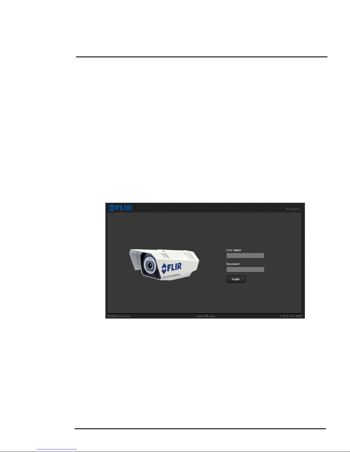
Figure 2-1: Camera Web Page Login Screen
Basic Operation and Configuration
2.4 Web Browser Interface
Use a web browser to connect to the camera as described below, and confirm it is streaming video.
Once the bench test is complete, use the web browser to make configuration changes as needed (for
example, set the IP address to an address that is compatible with the existing network). It is also a
good idea to run the FSM software and confirm it is working with the camera as expected.
It is possible to log into the camera using one of three User Names: user, expert, and admin.
By default all three accounts have the same password: fliradmin. The user login can be used to do
the initial bench test of the camera. The admin login must be used to make configuration changes
such as setting the IP address. The login passwords can (and should) be changed by the system
administrator to prevent unauthorized logins. For information on how to change the passwords, refer
to
section 2.6 “Basic Camera Configuration” on page 2-10.
Log into the Camera Web Page
Step 1 Open a web browser and enter: http:\\192.168.250.116. The login screen with a picture of
the camera will appear. The example below shows the FC-Series camera.
Step 2 Enter user for the User Name and fliradmin for the Password, and click Login.
427-0030-00-28 Version 110 Jun 2013 2-3

2
Figure 2-2: Camera Web Page Login Screen
Basic Operation and Configuration
The Live Video page will be displayed, with a live image from the camera on the left part of the
screen. Next to the FLIR logo along the top of the screen are some menu choices, including Live
Video (the red text indicates it is selected), Help and Log Off.
On the right side are some control buttons, and possibly an image of a joystick (if the camera has pan/
tilt capability).
If the live video is not displayed, refer to section 2.8 “Troubleshooting Tips” on page 2-17. In the lower
right of the web page there is a frame rate selector. This selector allows the user to change the rate at
which the frames are displayed in the browser. This rate controls the user’s own web browser only,
and does not affect the video streams to other users or to an NVR.
2.4.1 Camera Control and Status
In the lower left of the screen are two indicator “lights”: Control and Status.
Initially the Control light is off, as in the image above, indicating the user is not
able to control the camera immediately. When multiple users are connected to
a camera, only one user at a time can issue commands to the camera. If
another user has control of the camera, the Control light is yellow.
A user is able to request control of the camera by clicking on the yellow or
black “light”, or simply by sending a command to the camera. For example,
move the cursor over the video and select the “Zoom In” control (magnifying
glass with “+”) that appears in the lower left of the screen. The Status light may
turn off temporarily while waiting for the response from the camera. After a
short pause, the Control light should turn green. Observe what happens to the
image when the “Zoom In” control is clicked several times. Be patient, there
may be a slight delay between each command while the browser waits for a response from the
camera.
427-0030-00-28 Version 110 Jun 2013 2-4
2
Basic Operation and Configuration
If a command is sent to the camera when the user does not have control, the command will not be
executed, and it is necessary to send the command again once the light is green.
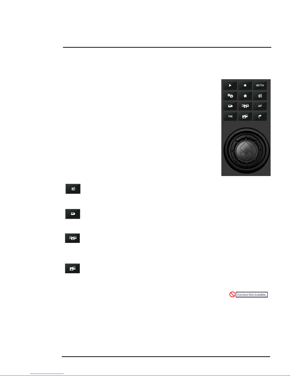
2.4.2 Web Control Panel
The control buttons on the right side of the page provide a way to control
the camera. When the mouse cursor is positioned over a button, a screen
tip is displayed which explains the function of the button.
This same web interface is used with various FLIR thermal cameras; some
are fixed mount cameras, such as the F-Series and FC-Series S cameras,
and some have pan/tilt capabilities, such as the PT-Series and D-Series.
As a result, some buttons appearing in the control panel may be disabled if
they do not apply to the camera in use.
When the web interface is used with a pan/tilt camera, an image of a
joystick appears below the control panel buttons. When the mouse is
positioned over the joystick, the camera can be moved (up-down and/or
left-right) by clicking and dragging the joystick in the appropriate direction.
For a fixed camera, the following buttons are enabled:
Save Snapshot
This button allows the user to save an image as a .jpg file. The destination folder for the
image is determined by the web browser that is used.
Perform IR NUC Calibration
This button causes the camera to perform a Non-Uniformity Correction operation (refer to
the
section 2.8.1 “Image freezes momentarily” on page 2-17).
Toggle Scene Preset
This button causes the camera to cycle through 5 different image settings. The Scene
Presets cause the image brightness and contrast to adjust. Depending on the time of day,
weather, and other conditions, one Scene Preset may be preferable to the others.
Toggle Polarity
This button changes the way various objects are displayed in the image, with hot objects
displayed as white and cold objects as black, or vice versa.
The other buttons on the control panel will be disabled for a fixed camera. In
the control panel, a disabled button is indicated with a grey color and when the
cursor is positioned over a disabled button, the screen tip indicates the
function is not available. The disabled buttons correspond to commands that are not used with a fixed
camera, but might be used to control a pan/tilt camera with multiple sensors.
427-0030-00-28 Version 110 Jun 2013 2-5
2
Basic Operation and Configuration
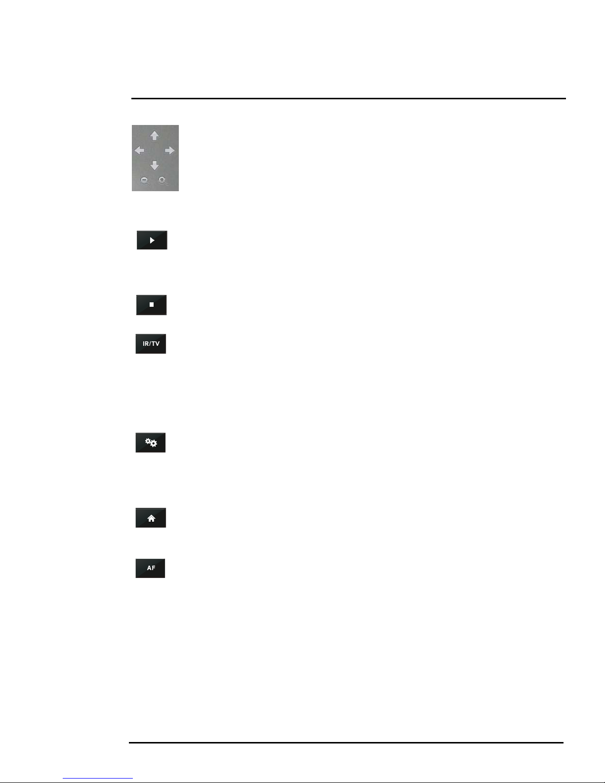
For a pan/tilt camera, when the mouse is positioned over the video window, some
controls appear in the lower left of the video image which allow the camera to be
panned left or right, or to be tilted up or down.
To move the camera, click on one of the
arrows.
As with a fixed camera, the zoom in and out controls also appear. To zoom in, click on
the Zoom In control (+); to zoom out, click the Zoom Out control (-).
The following control panel buttons are enabled for pan/tilt cameras:
Start Scan List
This button will cause the camera to start the current scan list, which is a set of preset
locations (each preset has a specific azimuth, elevation and zoom setting). The presets
are programmed on the camera using the web interface or the FSM software.
Sto p Scan List
This button causes the camera to stop (discontinue) the scan list.
Toggle Video Source
For a multi-sensor system with more than one video source (for example, a PT-Series
camera with a thermal IR camera and a daylight camera), this button causes the “active”
video source to be switched from one camera to the next. If the thermal IR camera is
active and the button is selected, it causes the daylight camera to become active, and vice
versa. This also causes the new active video source to be displayed in the Live Video
window.
Initialize Pan/Tilt
For a long-range multi-sensor system with a pan/tilt platform, this button causes the pan/tilt
to go through its startup initialization. For most pan/tilt security cameras, this button is not
needed since the pan/tilt will initialize automatically. For safety reasons, long-rage systems
with large camera lenses do not initialize automatically, so this button is used.
Pan/Tilt Home
This button causes the camera to go to the Home position. The Home position can be set
using the FSM software.
Autofocus
This button causes the active video source to perform an autofocus operation. If the active
source is a thermal camera with a fixed-focus lens, selecting this button causes an error
message to be displayed below the video window (“Function not available for this driver.”).
427-0030-00-28 Version 110 Jun 2013 2-6
2
Basic Operation and Configuration
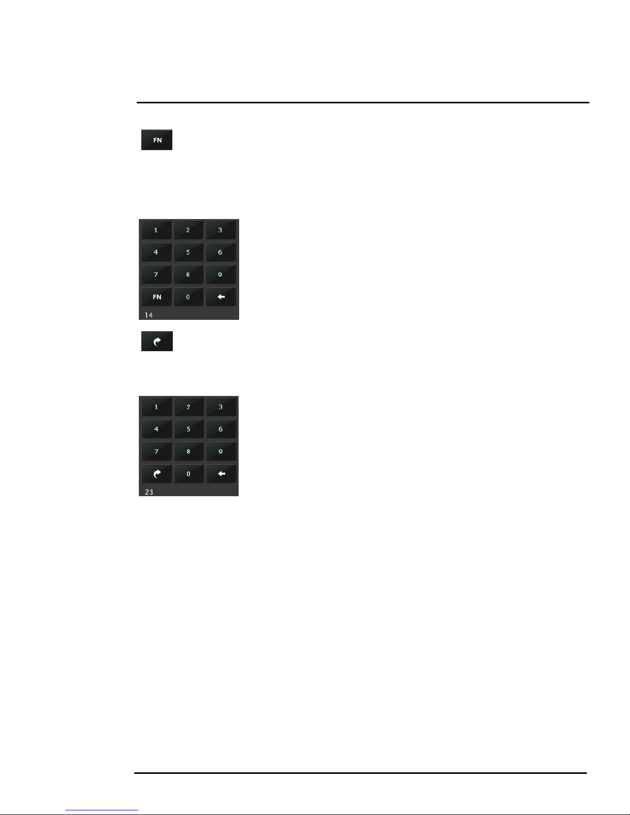
Function
Some cameras have additional features or functions which can be accessed using an
extra numeric function keypad. It is possible to create customized camera functions
through a “macro” interface which can be programmed through XML commands. For additional
information contact FLIR Technical Support for information about the Nexus XML-Based Control
Interfaces.
When the Function button is selected, the keypad changes to a numeric
keypad. As digits are selected, they are displayed below the keypad. To
execute the function, select the FN Function button again.
If an invalid function is entered, an error message appears below the video
window (“Function is not available in current mode.”). To return to the
Control Panel, select the Back button (left arrow).
Goto Preset
A camera can have a set of predetermined pan/tilt locations, each of which is known as a
“preset”. For example, a preset may be configured for each of the locations where security
surveillance is most needed, such as a gate, doorway, and other point of access.
When the Goto Preset button is selected, the keypad changes to a numeric
keypad. As digits are selected, they are displayed below the keypad. To
cause the camera to go to the entered preset, select the Goto Preset button
again.
To return to the Control Panel, select the Back button (left arrow).
427-0030-00-28 Version 110 Jun 2013 2-7
2
Basic Operation and Configuration
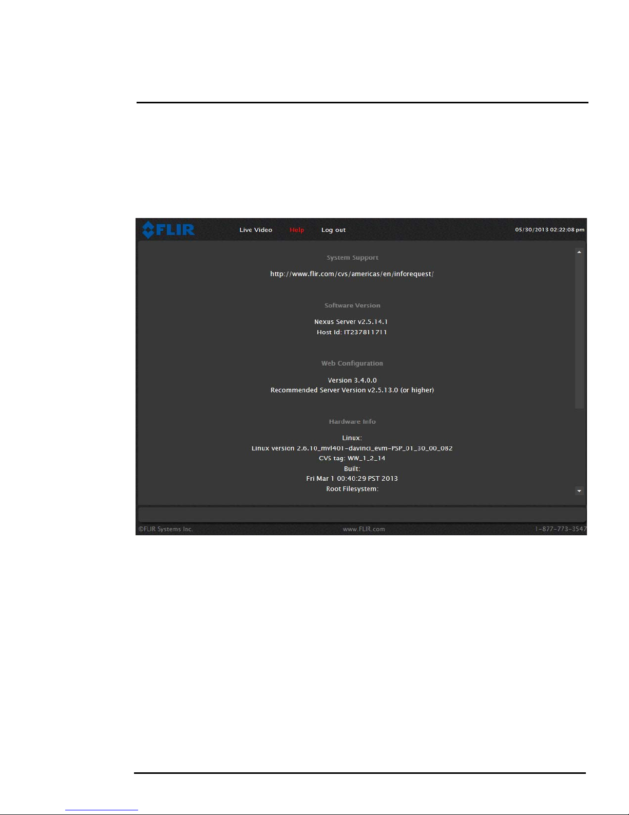
2.4.3 Help
At the top of the page, the Help menu displays software version information. This page has
information about the camera including hardware and software revision numbers, part numbers, and
serial numbers. If it is necessary to contact FLIR Technical Support for assistance, it will be helpful to
have the information from this page (such as Software Version) on hand.
2.4.4 Log Off
Use the Log Off menu entry to disconnect from the camera and stop the display of the video stream.
427-0030-00-28 Version 110 Jun 2013 2-8
 Loading...