

Page 1
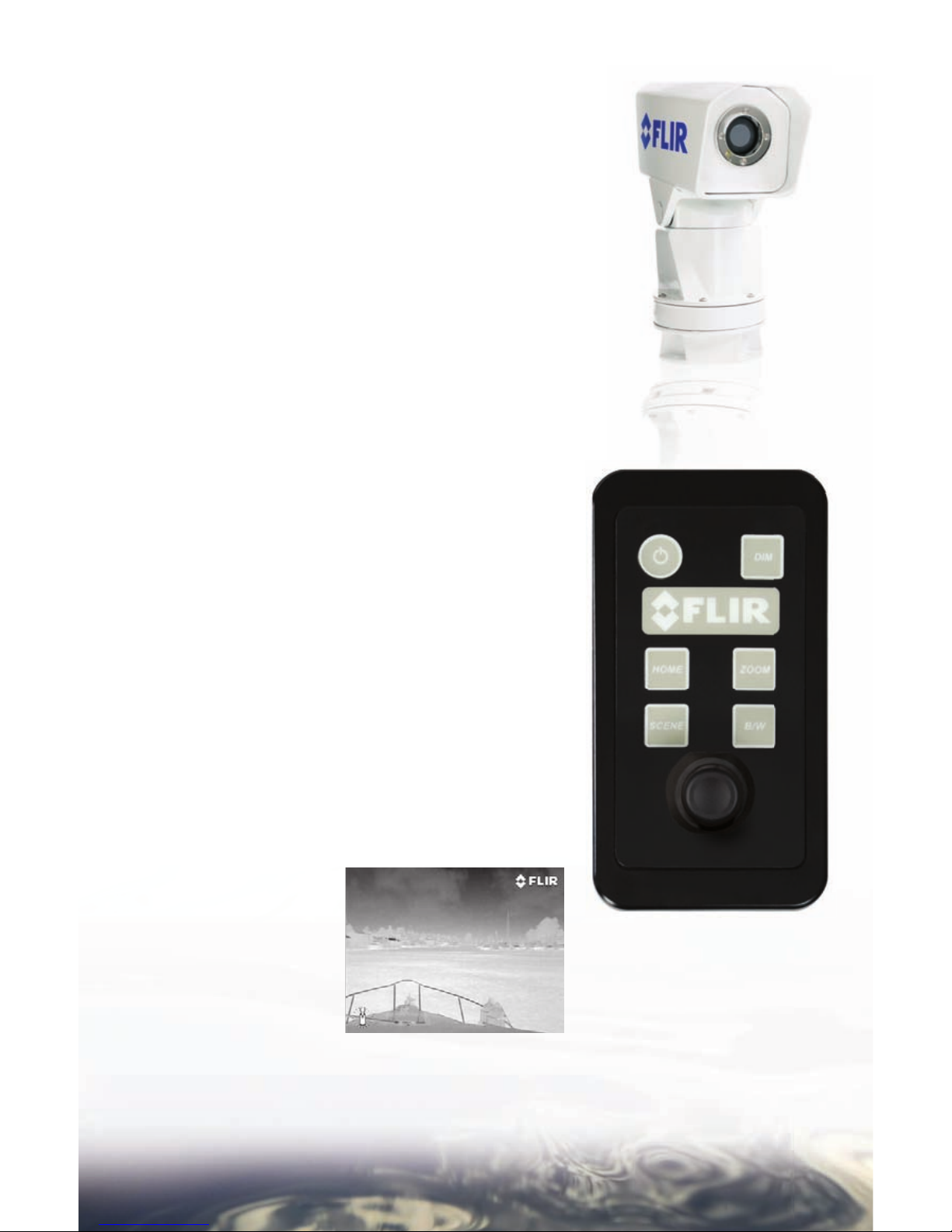
Navigator™ II
OPERATOR’S MANUAL
FOR STATIC AND PAN / TILT CONFIGUR ATI ON S
Page 2

Page 3
3
CONGRATULATIONS ON BUYING YOUR
N AV I G AT O R II …
Welcome to the pioneering world of maritime thermal imaging! e Navigator II is a stateof-the-art thermal imager that lets you see at night, through smoke and haze, without any
lighting at all. FLIR has been building thermal imagers for decades, and we are confi dent
that you will see why FLIR is the #1 name in infrared around the world.
ermal imaging technology has been a staple of military operations for years, but
FLIR has just recently made it available to the public, and only to a select few at that!
By purchasing a FLIR thermal imager, you have established yourself as a mariner on the
leading edge of technological advancement. Remember to register your Navigator II by
fi lling out the Registration card, and we will send you a nice “thank you” gift in return.
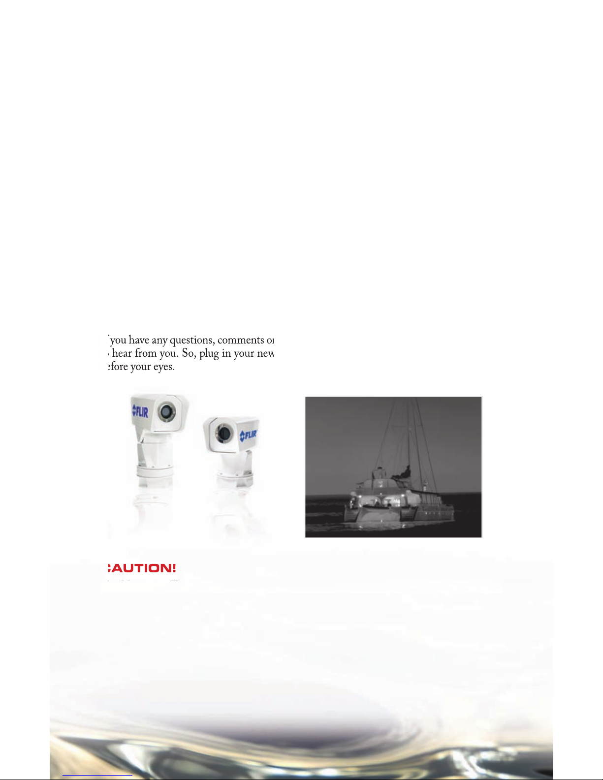
You will fi nd that the Navigator II is simple to use. ere are two versions of the Navigator
II: a Sta tic ver sion an d a Pan /T ilt ver sion . is ma nu al cov er s bot h pr oducts . Bo th v er sion s
use the same thermal imaging camera, but the fi xed version is simplifi ed in that it off ers
an “On” switch only, and an automatically optimized grayscale video output. e Pan/Tilt
version allows for 360° viewing, and has a number of added features like: color palettes, onscreen information, running modes and a programmable “home” position. We encourage
you to review the All About Infrared section that will help you to understand and interpret
the Navigator II’s thermal images.
If you have any questions, comments or concerns, give us a call at 877.747.3547 – we’d love
to hear from you. So, plug in your new Navigator II and watch the infrared world unfold
before your eyes.
CAUTION!
e Navigator II imaging system is not intended to be used as the primary navigation
system. It should be used in conjunction with other navigation aids and a primary manual
navigation system.
WARNING! e Navigator II imaging system is controlled by US export laws. ere
are special versions of this system that are approved for international distribution and
travel. Please contact FLIR Systems if you have any questions.
Page 4

4
TABLE OF CONTENTS
1 CAUTIONS 5
2 OPERATION 6
2.1 Navigator II Static Version 7
2.2 Navigator II Pan/Tilt Version 8
3 CARING FOR YOUR NAVIGATOR 10
3.1 Care and Maintenance 11
3.2 Replacing the fuses 11
3.3 Cleaning 11
4 FUNDAMENTALS OF INFRARED 12
4.1 All About Infrared Technology 13
4.2 Even More About Infrared 14
5 APPENDIX 18
5.1 Parts 19
5.2 Accessories 20
5.3 Specifi cations 21
Page 5

5
CAUTIONS
In the Navigator II Operator’s Manual, CAUTION notices indicate a potential hazard,
which, if not avoided, may harm you, someone else, or the Navigator II. For greater safety,
and to achieve the highest levels of performance from your Navigator II, always follow these
Cautions when handling and operating your Navigator II camera system.
CAUTION!
Do not use the Navigator II imaging system as your primary navigation system. Use it •
in conjunction with other navigation aids and a primary manual navigation system.
Do not open the Navigator II camera body for any reason. Disassembly of the camera •
(including removal of the cover) can cause permanent damage and will void the
warranty.
When cleaning your Navigator II, be very careful not to leave fi ngerprints on the •
Navigator II’s infrared camera optics. ey are treated with a special coating that can be
permanently damaged by the oils in your skin. Refer to the Caring For Your Navigator
II section for instructions.
e Navigator II runs off of 12 VDC. Plugging it in to any other power level will •
damage the system.
Do not use the thermal imager to look at high-intensity radiation sources like lasers, arc •
welders, the sun, etc., as this can damage the imager.
Navigator II is designed to withstand the shocks and vibrations commonly encountered •
in the normal maritime environment. Don’t expose the camera to excessive impacts.
Only a qualifi ed marine electronics technician should install your Navigator II. FLIR •
assumes no responsibilty for improper installation.
CAUTION!
Failure to follow the caution may result in damage to the Navigator II.
Page 6
6
OPERATION
Page 7
7
Operating Your Navigator II
(STAT I C ve r sion )
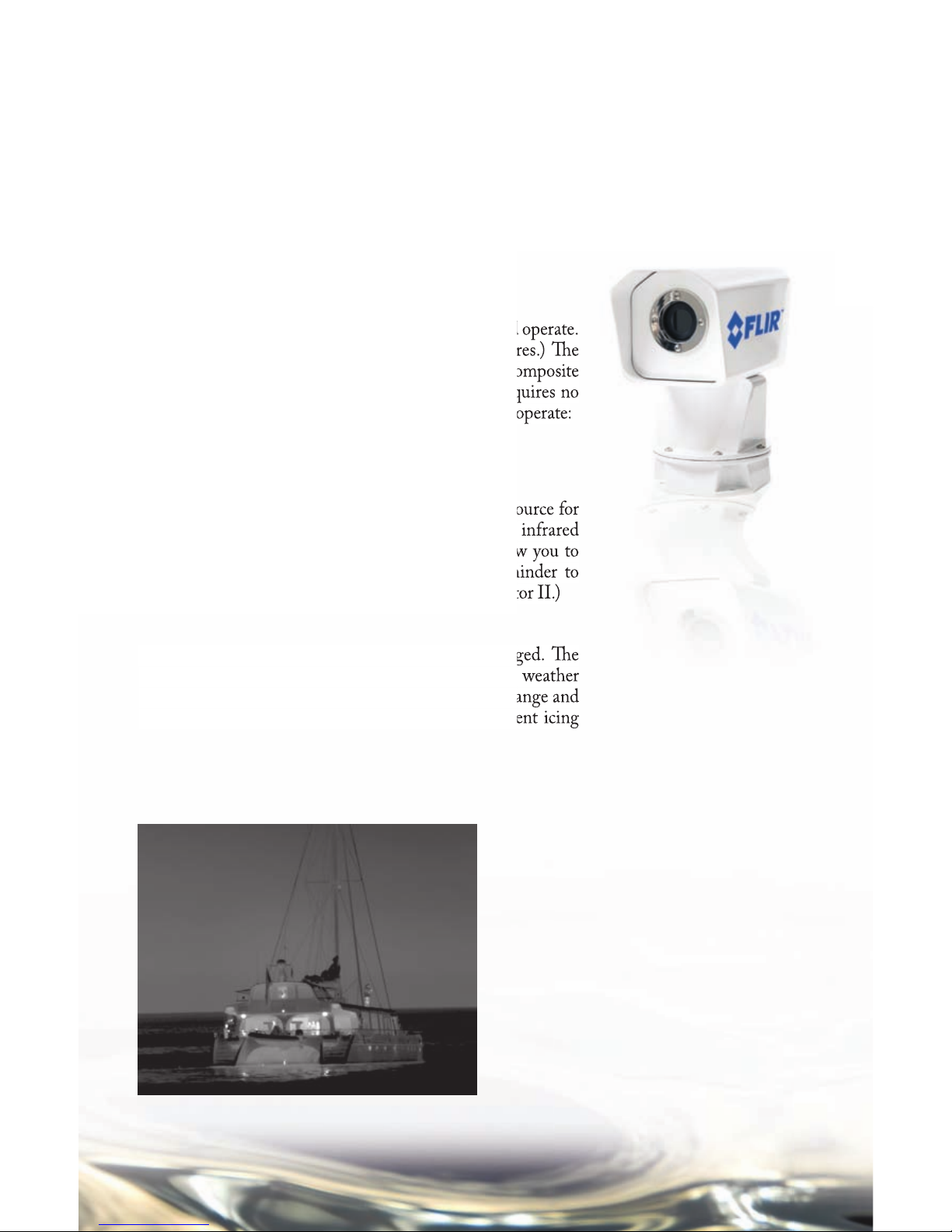
e static Navigator II is simplicity itself to install and operate.
(See the Installation Guide for installation procedures.) e
system operates on 12 volts DC, outputs standard composite
video (NTSC or PAL formats are available), and requires no
camera adjustments. Follow this simple procedure to operate:
Turn on the camera using the On/Off switch. •
Turn on your FLIR display.•
Make sure you’ve selected the Navigator II as the source for •
your display, and start looking at your Navigator II’s infrared
video. (Most multi-function displays (MFDs) allow you to
select from various available inputs. is is a reminder to
select the proper input when operating your Navigator II.)
e Navigator II is completely sealed and very rugged. e
camera is qualifi ed for operation in all types of weather
conditions over the specifi ed operating temperature range and
includes an automatic window heater that will prevent icing
under most conditions.
NAVIGATOR II OPERATION
FLIR makes two versions of the Navigator II: the Static version, which stays pointed in one
direction relative to the vessel (usually straight ahead), and the Pan/Tilt version that can
look up and down (+/- 45° relative to the horizon), and 360° around. is manual contains
operations instructions for both versions. Make sure you use the instructions that apply to your
confi guration of Navigator II.
Page 8
8
Opera ting Your Nav iga tor II
(PAN/ TILT version)
e Pan/Tilt version of the Navigator II is a little more
complicated to use than the Static version, but not much. e
qualifi ed technician who installed your Navigator II isolated
your Navigator II from vessel power with a customer-supplied
switch or circuit breaker tied-on to your vessel’s power bus.
Make sure that this switch or circuit breaker is turned on,
then turn on your display and select the Navigator II as the
video source for your display. From there, use the controls on
the Joystick Control Unit (JCU) to operate and confi gure
your Navigator II. If you choose to operate your Navigator
II with engines off , be aware that this may drain power from
your batteries, unless connected to shore power and equipped
with a suitable battery tender.
On/Off – turns the Navigator II on and off . When the
On/Off switch is turned to the On position, 2 FLIR
splash screens will display for 5 seconds each. After this,
the infrared image will display, and the system is ready for
operation. Note that the Navigator II will still draw a small
amount of power when off .
Joystick – allows the operator the control where the
Navigator II is looking. Move the Joystick to the left or right
to rotate the camera in the corresponding direction; tilt it
forward and back to tilt the camera up and down.
DIM – controls the brightness of the JCU panel; this
control is active any time power is on. Dimming the control
helps to protect the operator’s night vision. Simply press the
button to cycle through the four pre-set brightness levels.
HOME – e Home position is a user-programmable set of
pointing angles, usually 0°-0° (straight ahead and level with
the horizon), that operators can use as a reference, and as a rest
position when navigating for long periods. To set the Home
position, use the Joystick
to point the camera’s line
of sight to the position you
want to set as “Home,” press
and hold for the HOME
button for 4 seconds, and
the Navigator II save this
position as Home. (When
the Home symbol fl ashes,
the new Home position has been saved in memory.) When
you want to drive the camera to this Home position, press and
release the HOME button.
NAVIGATOR II OPERATION
Page 9

9
ZOOM – toggles the 2X
zoom setting on and off . e
Navigator II Pan/Tilt has a
2X electronic zoom. Press
the Zoom button to select
and de-select this option. A
“2X” icon will appear when
this control is active.
SCENE – cycles through
Night Running, Day
Running, Man Overboard,
or Night Docking gain
settings to change the
brightness and contrast
of the image. Varying
environmental conditions
may make one setting
more appropriate than
the others for a given
operation. Experiment with
the diff erent settings and
choose the one that gives
you the best image for your
conditions.
Night Running
Man Overboard
Day Running
Night Docking
White Hot
Fusion
Red Hot
Black Hot
Rainbow
B/ W – toggles between the
available image presentation
modes: white hot, black hot,
red hot, rainbow and fusion.
Hot objects appear black,
white, or red respectively
depending on the selected
mode. e choice of video
image mode is strictly a
personal preference and you
should experiment to fi nd
your preferred mode.
Page 10

10
CARE AND MAINTENANCE
Page 11

11
CARE AND MAINTENA NCE
Troubleshooting
e Navigator II is a simple, yet sophisticated device, built to provide years of trouble-free use.
If you do run into problems with your Navigator II, try these simple steps:
If the camera will not produce an image, check the fuse fi rst. e fuse is on the main power line
in a rubberized cover. Remove the f use and check to see if it is still intact (see instructions below).
If the fuse has blown, determine the cause of the blown fuse, fi x the problem, and replace with
a 5-Amp fuse.
Check the wiring at both the electrical panel and at the termination to the JCU. Ensure that
the contacts are clean dry and free from corrosion. Refer to the Navigator II Installation Guide
for proper wiring instructions. If maintenance on the wiring connection is required, have an
authorized service representative make the appropriate repairs.
If the camera still will not produce an image, check the video connection at the camera and
at your display. If the connectors appear to be properly engaged but the camera still does not
produce an image, have an authorized service representative make the appropriate repairs.
Replacing the fuses
Caution! Replace system fuses with the same value and type provided at the time of purchase.
Using fuse values other than the ones supplied by FLIR Systems may cause permanent damage
to the unit and may void the warranty.
To replace the fuse, ensure power is off , remove the fuse from the fuse holder, remove the fuse
and replace with one of the supplied 5-Amp fuses.
CAUTION!
Do not open the camera body for any reason. Disassembly of the camera (including
removal of the cover) can cause permanent damage and will void the warranty.
CAUTION!
Clean the camera window only with low-pressure fresh water and a soft cloth.
CAUTION!
Improper care of the camera window can cause damage to its anti-refl ective coating,
degrade the camera’s performance, and void the camera warranty.
e camera housing has a durable marine coating. Rinse the camera housing with very
low-pressure fresh water to keep it clean. If the front window of the camera gets water
spots, wipe it with a clean lens cloth folded in fourths and dampened with fresh water.
Cleaning
Page 12

12
ALL ABOUT INFRARED
Page 13

13
ALL ABOUT INFRARED
Intro
e Navigator II detects diff erences in heat and displays them
as black and white TV video. It may look like a black and
white version of what your eyes see, but it’s not. e Navigator
II sees heat, not light. e sooner you can understand and get
comfortable with that diff erence, the more you will enjoy this
incredible technology.
Why things look the way they do
e Navigator II’s thermal imager makes video images from
diff erences in heat, not from the light you see every day. It senses
the minute diff erences in heat between objects, and (in white hot
mode) displays the warmer objects as white (or lighter shades of
gray), and colder objects as black (or darker shades of gray).
Everything you encounter in your day-to-day existence gives off
heat – even ice! Chances are that the hotter something is, the
easier it will be to see.
While most things give off their own heat, some things actually
refl ect the heat given off by other things. Water and polished
metal, for example, aren’t as hot as they appear when they refl ect
sunlight, or the heat generated by other vessels.
What’s more, some things that are the same temperature (or
close to it) look diff erent because of their diff erent surface
textures.
IR energy doesn’t go through glass or water effi ciently, so
Navigator II won’t let you see through glass.
ermal imagers are passive – they only receive incoming
energy. ey don’t “see through” anything. While you might
think you are seeing through the hull of the vessel to see the
bulkheads and heat from the engine, you’re not. ese elements
are actually changing the temperature of the hull itself, allowing
you to see the bulkheads and the hot engine room.
As you experiment with your Navigator II, you will begin to
see a world of heat. Consider every object you view in terms of
how it will look “thermally” as opposed to how it looks in the
visible spectrum.
Weather
Environmental conditions, including time of day, humidity,
and precipitation, will aff ect image quality and contrast. Fog,
smog and rain will decrease the range at which you can detect
a given target. After sunset, objects warmed by the sun during
the day will radiate their stored heat for several hours. Early
in the morning, many of these objects will appear cooler than
their surroundings, so be sure to look for subtle temperature
diff erences in the scene, not just hot (white) targets.
Page 14

14
EVEN MORE ABOUT INFRARED
Page 15

15
EVEN MORE ABOUT INFRARED
At fi rst blush, new technologies can appear intimidating. Infrared cameras may seem imposing,
but they are not so diff erent from digital camcorders. In fact, you can get years of enjoyable,
productive use out of your Navigator II without knowing anything in this section. But, if you
would like to learn more about thermal imaging – how it was discovered and developed – read
on.
Infrared – the early years
e road to modern thermal imaging began way back in 1666,
when Sir Isaac Newton used a prism to split white light into
the colors of the rainbow. Today, we call this rainbow the
“Visible Light Spectrum.”
In addition to looking kind of cool, Newton’s experiment
proved that sunlight was not an indivisible whole, as once
thought, but was made of a range of subtly diff erent light
energies.
In 1800, Sir William Herschel took this discovery one step
further, when he found that the diff erent colors of the Visible
Light Spectrum have diff erent temperatures, which increase
from the violet band of the spectrum to the red.
He did this by splitting sunlight with a prism and placing the
darkened bulb of a thermometer in each color band. When he
moved a thermometer past the red color band, Herschel found
that the energy beyond visible red light was warmer than the
red light itself. His name for this energy was “Calorifi c Rays.”
Today we call it “infrared radiation” or “thermal energy,” and
use the two terms interchangeably.
High school physics revisited
Infrared radiation combines with Gamma rays, X-rays, Ultra Violet, Visible Light, Microwaves
and Radio Waves to form a range of energy called the Electromagnetic Spectrum.
ese are not exotically independent types of energy – in fact, the primary diff erence between
each of these types of radiation its wavelength: Radio Waves have the longest wavelength and
Gamma Rays have the shortest. Wavelengths are measured in micrometers, or “microns” (µ),
which are equal to one millionth of a meter.
Infrared radiation wavelengths are longer than those of visible light. Visible light wavelengths
range from 0.4µ to 0.75µ, while infrared is between 1µ and 15µ. ermal imagers make pictures
from either the 3-5µ range (called mid-wave IR [MWIR]), or the 8-12µ range [called long-wave
IR (LWIR)).
ermal images may look like black & white photographs, but the two types of images are
actually quite diff erent. Photographic cameras create images from refl ected light energy, while
infrared cameras create images from radiated thermal energy.
e amount of radiated thermal energy that reaches the Navigator II’s imager is a function
of the viewed object’s temperature and emissivity. is relationship between temperature and
emissivity can be a complex one, but we’ll sum it up with two basic rules:
1) e hotter an object gets, the more infrared energy it radiates. Even a small increase in
temperature can result in a dramatic increase in the amount of radiated thermal energy.
2) At a given temperature, the amount of thermal energy radiated by an object depends on its
Page 16

16
emissivity. Emissivity is the measure of an object’s effi ciency at radiating thermal energy. For
example, shiny metals are poor emitters. Instead of radiating their own thermal energy, they
tend to refl ect radiation from their surroundings.
Infrared, from theory to practical application
Infrared imagers operate by detecting the relative intensities of thermal energy radiated from the
surfaces of objects, and displaying these intensities in black and white video as shades of gray.
ey do not show a “heat picture.” Even if an object is very hot, it may not display well if there
is little or no temperature contrast between the object and its surroundings.
ermal imagers primarily detect thermal energy radiated from an object’s surface; thermal
imagers can’t “see through” much of anything.
As you look at the thermal images created with your Navigator II, you will see multiple sources
of thermal energy in addition to your main object of interest. When looking at a scene with
a large number of heat sources, it can get confusing trying to sort it all out. Kirchhoff ’s Law
is an easy way to account for the diff erent sources of thermal radiation you see in your images.
Kirchhoff says that all of the thermal radiation in an image has been Emitted (given off by the
object), Transmitted (passed through the object), or Refl ected (bounced off the object).
Most of the strong energy sources you will see in a given scene are from “emitted” energy. at
is, they are giving off heat energy. Examples of strong emitters of thermal energy include people
and boat engines.
ermal energy doesn’t pass through much, but it does “transmit” through some plastics. When
a material is not transparent to infrared radiation, it is said to be “opaque.” Most commonly
viewed materials are opaque to infrared radiation.
Materials that mirror the infrared signatures around them are “refl ective.” Everything is
refl ective to one degree or another, but the most highly refl ective objects are those made of
polished, unpainted metal. Painted metals, glass, and even wood can display greater or lesser
degrees of refl ectivity, but this becomes dependant upon myriad factors like their surface
coatings, textures, and the angles from which they are viewed. Refl ections can appear hotter
or colder than they really are, based on what they are refl ecting. Sun refl ecting off of polished
chrome looks quite bright, and a common mistake is to think that this section of chrome has
suddenly become very hot. It hasn’t, it is just refl ecting energy from the sun.
Another reason to care about the weather
e time of day and weather conditions in which you use your Navigator II can have a signifi cant
infl uence on how objects look on the screen. Remember that thermal imagers detect and display
diff erences in infrared radiation. If an object and its background do not display any appreciable
Page 17

17
temperature diff erence, that object will be very diffi cult to detect. erefore, the time of day
during which your Navigator II is used can have a direct impact on your ability to detect and
recognize objects.
When things are exposed to the sun, they absorb infrared radiation. As the duration of this
exposure increases throughout the day, thermal contrast between targets decreases.
When the sun begins to set, objects begin to cool. In doing so they radiate some of this stored
thermal energy back into the atmosphere, and a certain degree of thermal contrast is restored.
is increase in contrast continues until the sun comes up the following morning. is daily
sequence of heating and cooling is called the “Diurnal Cycle.”
Atmospheric conditions can limit the range and imaging performance of your Navigator II.
Under ideal conditions, most of the infrared energy radiated from an object gets through the
atmosphere and to the imager. Under typical conditions however, atmospheric moisture and
dust scatter and absorb some of the radiated energy before it reaches the imager. e eff ect of this
is to weaken the over-all thermal signal and shorten the range at which you can detect it.
e weather can impact more than just the range at which the Navigator II can detect a
specifi c object – it can also aff ect an entire scene’s thermal contrast and eff ect overall system
performance.
Cloud cover eff ects the diurnal cycle in two ways:
First, cloud cover decreases the amount of solar radiation allowed to strike the earth’s surface,
keeping days cooler and nights warmer.
Second, clouds form a layer of insulation over the earth that prevents heat from being radiated
back into space at night.
Like clouds, humidity tends to reduce contrast and wash out the eff ects of the diurnal cycle.
While humidity doesn’t block out solar radiation during the day, it does tend to keep nights
warmer.
Rain acts diff erently because water tends to cool the surfaces it touches. Remember that thermal
imagers only detect diff erences in thermal energy radiated from an object’s surface; therefore,
rain can markedly reduce a scene’s contrast. While rain reduces contrast between objects with no
heat source, it will allow objects with a heat source (like, people, animals, running vehicles, some
structures) to show up with even more contrast to their now-cooler surroundings.
Conclusion
Tired? Confused? No problem. If you see something through your Navigator II that looks
suspicious, don’t get too hung up on trying to fi gure out why it looks the way it does. Just
remember: if something is in your way, play it safe and steer clear!
Page 18

18
APPENDIX
Page 19

19
PAN/TILT NAVIGATOR II FLIR Part Number
Navigator II camera with attached 25’
cable and wired Joystick Control Unit
with fuse holder. e camera and
Joystick come with gaskets attached.
Navigator II slow video (9 Hz) camera
with attached 25’ cable and wired
Joystick Control Unit with fuse holder.
e camera and Joystick come with
gaskets attached.
APPENDIX
Parts List
e Navigator II includes the following thermal imaging components:
If the components you have are diff erent from those enumerated in this Parts List, please call us
immediately at 877.747.3547.
white color, NTSC 432-0001-09-00
white color, PAL 432-0001-11-00
white color, NTSC 432-0001-09-00S
white color, PAL 432-0001-11-00S
STATIC NAVIGATOR II FLIR Part Number
Navigator II camera with attached 25’
cable and wired On/Off switch with
fuse holder. e camera and switch
plate come with gaskets attached.
Navigator II slow video (9 Hz) camera
with attached 25’ cable and wired
On/Off switch with fuse holder. e
camera and switch plate come with
gaskets attached.
white color, NTSC 432-0001-01-00
white color, PAL 432-0001-03-00
white color, NTSC 432-0001-01-00S
white color, PAL 432-0001-03-00S
Two sets of mounting hardware for the camera, one set of mounting hardware for the On/Off switch,
5-amp fuses, 10 cable clips and wood screws, and a BNC to RCA adapter.
Navigator II Operator’s Manual 432-0001-00-11
Two sets of mounting hardware for the camera, one set of mounting hardware for the Joystick
Control Unit, 5-amp fuses, 10 cable clips and wood screws, and a BNC to RCA adapter.
Navigator II Operator’s Manual 432-0001-00-11
Page 20

20
For the STATIC Navigator II FLIR Part Num ber
25’ Extension Cable for Static Navigator II 308-0128-00
50’ Extension Cable for Static Navigator II 308-0130-00
Video Extension Kit, contains:
Video amplifi er, 25’ video cable, 50’ video cable,
and wiring instructions 432-0001-14-01
FLIR lens cleaning kit
For the PAN / TILT Navigator II FLIR Part Number
25’ Extension Cable for Pan & Pan Tilt Navigator II 308-0129-00
50’ Extension Cable for Pan & Pan Tilt Navigator II 308-0131-00
Video Extension Kit, contains:
Video amplifi er, 25’ video cable, 50’ video cable,
and wiring instructions 432-0001-14-01
Dual Station Accessory Kit, contains:
Joystick with 50’ cable and installation instructions 432-0001-14-03
“Deluxe” Dual Station Accessory Kit, contains:
Joystick with 50’ cable, a Video Extension Kit,
and installation instructions 432-0001-14-02
FLIR lens cleaning kit
Accessories
FLIR Systems makes a family of extension cables and remote video/control station kits for
Navigator II systems. e cables may be combined to a total length of 100 feet. e part numbers
are as follows:
Page 21

21
Static Pan/Tilt
System Overview
Size 7.3 ” x 4. 0 ”x 7. 4” 7.3”x4.0”x9.5”
Weight 6lb 7lb
Thermal Imaging Performance
Sensor type 320 x 240 Microbolometer 320 x 240 Microbolometer
FOV 36° x 27° 36° x 27°
E zoom N/A 2x
System Specifi cations
Pan/Tilt Coverage N/A 360° Az/ +/-45°
Video Output NTSC or PAL NTSC or PAL
Power Requirements 12V D C 12V D C
Environmental
Operating Temp -25°C to 55°C -25°C to 55°C
Joystick Control Unit (JCU)
Dimensions 3.25” x 6.13” 3.25” x 6.13”
Specifications
Page 22

22
Document Number: 432-0001-00-11
© FL IR Sy stems, Inc ., 20 07. Al l r ight s res er ve d worldw id e.
No parts of this manual, in whole or in part, may be copied,
photocopied, translated, or transmitted to any electronic
medium or machine readable form without the prior
written permission of FLIR Systems, Inc.
Names and marks appearing on the products herein
are either registered trademarks or trademarks of FLIR
Systems, Inc. and/or its subsidiaries. All other trademarks,
trade names, or company names referenced herein are
used for identifi cation only and are the property of their
respective owners.
is product is protected by patents, design patents, patents
pending, or design patents pending.
e Navigator II imaging system is controlled by US
export laws. ere are special versions of this system that
are approved for international distribution. Please contact
FLIR Systems if you have any questions.
FLIR Systems, Inc.
70 Castilian Drive
Goleta, CA 93117
Phone:
+1.888.747.FLIR (+1.888.747.3547)
www.fl ir.com
Page 23

Page 24

Equipment described herein may require US Government authorization for export purposes. Diversion contrary to US law is prohibited.
©2007 FLIR Systems, Inc. Specifi cations are subject to change without notice, check our website: w ww.fl ir.com.
Document Number: 432-0001-00-11
FLIR Systems, Inc.
CVS World Headquarters
FLIR Systems, Inc.
70 Castilian Dr.
Goleta, CA 93117
USA
PH: + 1 877 773 3547
PH: + 1 805 964 9797
FX: + 1 805 685 2711
sales@fl ir.com
EUROPE
CVS Eurasian Headquarters
FLIR Systems CVS BV
Charles Petitweg 21
4847 NW Teteringen Breda
Netherlands
PH: + 31 (0) 765 79 41 94
FX: + 31 (0) 765 79 41 99
fl ir@fl ir.com
FLIR Systems, Inc.
Corporate Headquarters
FLIR Systems, Inc.
27700A SW Parkway Ave.
Wilsonville, OR 97070
USA
PH: + 1 877 773 3547
FX: + 1 503 498 3904
sales@fl ir.com
 Loading...