

flir.com/security/pro
MODEL: N347BW4
SERIES
QUICK START GUIDE
English Version 2.0
FLIR Systems, Inc., Copyright © 2017
As our products are subject to continuous improvement, FLIR Systems
Inc. reserves the right to modify product design, specifications and
prices, without notice and without incurring any obligation. E&OE
4MP Motorized Varifocal
Network Bullet Camera
flir.com/security/pro
VISIT
Compatible Accessories
IT’S ALL ON THE WEB!
FCC Notice
This equipment has been tested and found to comply with
the limits for a Class A digital device, pursuant to Part
15 of the FCC Rules. These limits are designed to provide
reasonable protection against harmful interference when
the equipment is operated in a commercial environment. This
equipment generates, uses, and can radiate radio frequency
energy and, if not installed and used in accordance with the
instruction manual, may cause harmful interference to radio
communications. Operation of this equipment in a residential
area is likely to cause harmful interference in which case the
user will be required to correct the interference at his own
expense.
N347BW4_QSG_EN_R2
This security camera has several mounting options:
Safety Precautions
• Use an appropriate low-voltage power cable to prevent fire
or electrical shock.
• Make sure to install the camera in an area that can support
the camera weight.
• There are no user-serviceable parts inside the camera. Do
not disassemble the camera.
• Do not clean the lens cover with an abrasive cleaning
material. Use a soft cloth to clean the lens cover.
• Camera is rated for outdoor use (IP66), but is not intended
for submersion in water.
• Extend the Ethernet cable run for your camera up to 300ft.
You can use an RJ45 coupler or network switch to connect
male ends of Ethernet cable together. A maximum of 3
connections is recommended.
Weights & Dimensions
3.7”/
95mm
2.4lbs / 1.1kg
Weight
Accessories Model Numbers
Junction Box S1JF2G
Corner Mounts S1JF2G with S1RA2G
Pole Mounts S1JF2G with S4PA2G
10.7” / 273mm
Cap housing
RJ45 plug
Outer seal
Inner
seal
Cap-sealing nut
Ethernet
connector
Using the RJ45 Cap (Optional)
ATTENTION:
The supplied RJ45 cap is weather-resistant. Seal the cap with
silicone if it will be exposed to precipitation regularly.
1
2
3
4
Fit the outer seal over your camera’s Ethernet connector
and insert the inner seal into the cap housing.
Run the stripped end of an Ethernet cable through the
parts of the RJ45 cap, as shown above.
Terminate the Ethernet cable with an RJ45 plug, and plug
the cable into your camera’s Ethernet connector.
5
Screw the cap housing onto the Ethernet connector.
Screw the cap-sealing nut tightly into the cap
housing.
3.9” / 97.8mm
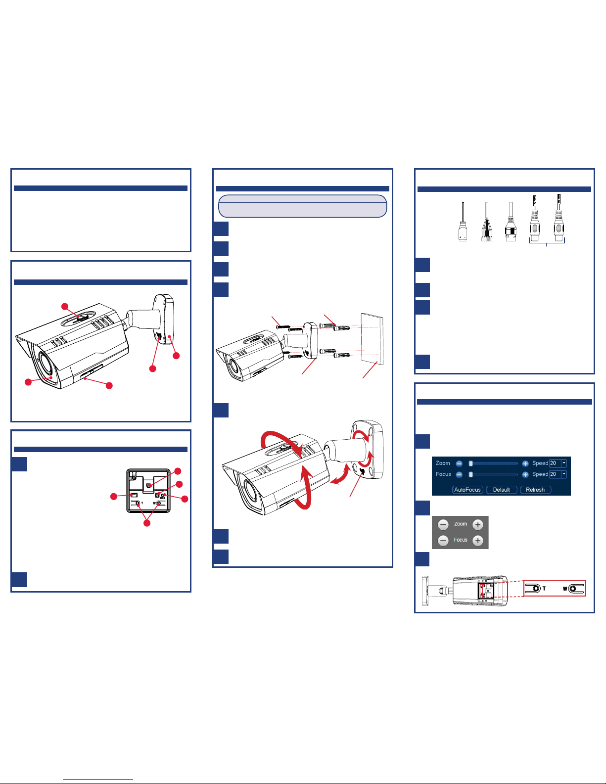
Adjusting Zoom and Focus
1
2
Adjust the camera’s zoom and focus using an NVR or the web
interface. For more information, see your NVR’s instruction
manual on www.flir.com/security/pro.
NVR: Right-click on the camera’s live view and then
click AutoFocus. Use the sliders to adjust the zoom and
focus.
Web Interface: Use the controls in the right-hand panel
to adjust the zoom and focus.
Package Contents
• 1× 4MP Network Bullet Camera
• 4× Mounting Screws & Drywall Anchors
• 1× Security Screwdriver
• 1× Mounting Template
• 1× RJ45 Cap
• 1× Video Test Cable
Connecting the Camera
A
D
Power Input: If not using PoE, connect the camera to a
24VAC power source. See the rating label on the camera
for minimum power requirements.
Ethernet Connector: Connect the camera to an NVR
or a router or switch on your network using CAT5e or
better Ethernet cable (not included). PoE supported
(802.3af).
NOTE: For instructions on weatherproofing the Ethernet
connection, see “Using the RJ45 Cap (Optional)” on the
back of this guide.
B
C
Alarm I/O (optional): Connect alarm/sensor devices (not
included).
Audio I/O (optional): Connect a self-powered microphone
(audio in) or speaker (audio out).
A B C D
3
Manual Zoom In/Out: Located in the camera’s service
compartment, press T to zoom in and W to zoom out.
Service Compartment Overview
A
B
Use the included mounting template to mark holes for
the mounting screws and camera cable.
ATTENTION:
Test the camera prior to selecting a permanent mounting location by
temporarily connecting the camera(s) and cables to the NVR.
Installing the Camera
1
Drill holes for the mounting screws and camera cable.
NOTE: Use the included drywall anchors if needed.
2
3
4
5
7
Connect cables as shown in the section “Connecting the
Camera”.
Attach the camera base to the mounting surface using
the included mounting screws (4×).
Use the included security screwdriver to loosen the
adjustment screw on the camera base. Make the
necessary camera angle adjustment.
Remove the vinyl film from the camera lens when your
installation is complete.
Camera Overview
N347BW4_QSG_EN_R2
B
A
D
C
A. Light Sensor and IR LEDs
B. Sun Shield Screw
C. Adjustment Screw
D. Camera Base
E. Service Compartment
Mounting
screws (4×)
Camera
base
Mounting
surface
Drywall
anchors (4×)
Adjustment
screw
E
Use the included security screwdriver to open the
compartment cover.
Close the compartment cover and secure the screws
when finished.
A
C
D
A. microSD Slot: Insert a microSD
card (not included) into the slot.
microSD card Class 10
supported.
B. Video Test Port: Connect
a test monitor using the
included video test cable.
C. Reset Button: Press and
hold the button for
5 seconds using a
thin object to reset the
camera to default settings.
B
Tighten the adjustment screw when finished.
6
E
D. Manual Zoom In/Out: See
“Adjusting Zoom and Focus”
section for details.
E. For Service Purposes only.
 Loading...