

Page 1
Ariel Gen III
User and
Installation
Guide
CM-3304/CM-3308
Ver. 5 March 10, 2019
i
Page 2

© 2019 FLIR Systems, Inc. All rights reserved worldwide. No parts of this manual, in whole or in part, may
be copied, photocopied, translated, or transmitted to any electronic medium or machine readable form
without the prior written permission of FLIR Systems, Inc.
Names and marks appearing on the products herein are either registered trademarks or trademarks of
FLIR Systems, Inc. and/or its subsidiaries. All other trademarks, trade names, or company names
referenced herein are used for identification only and are the property of their respective owners.
This product is protected by patents, design patents, patents pending, or design patents pending.
The contents of this document are subject to change.
FLIR Systems, Inc.
6769 Hollister Avenue
Goleta, California 93117
USA
Phone: 888.747.FLIR (888.747.3547)
International: +1.805.964.9797
For technical assistance, please call us at +1-800-254-0632 or visit the Service & Support page at
www.flir.com/security.
Important Instructions and Notices to the User:
Modification of this device without the express authorization of FLIR Commercial Systems, Inc. may void
the user’s authority under FCC rules to operate this device.
ii
CM-3304/CM-3308 User and Installation Guide
March 10, 2019
Page 3

Proper Disposal of Electrical and Electronic Equipment (EEE)
The European Union (EU) has enacted Waste Electrical and Electronic Equipment
Directive 2012/19/EU (WEEE), which aims to prevent EEE waste from arising; to
encourage reuse, recycling, and recovery of EEE waste; and to promote
environmental responsibility.
In accordance with these regulations, all EEE products labeled with the “crossed
out wheeled bin” either on the product itself or in the product literature must not be
disposed of in regular rubbish bins, mixed with regular household or other commercial waste, or by
other regular municipal waste collection means. Instead, and in order to prevent possible harm to the
environment or human health, all EEE products (including any cables that came with the product)
should be responsibly discarded or recycled.
To identify a responsible disposal method nearby, please contact the local waste collection or
recycling service, the original place of purchase or product supplier, or the responsible government
authority in the area. Business users should contact their supplier or refer to their purchase contract.
Document History
Version
Date
Comment
Ver 0.1
September 11, 2017
Initial FLIR Release
Ver 0.3
Dec 2018
Firmware upgrade (Analytics)
SD Card min/max
Ver 0.4
Feb 2019
Camera License for Basic Video Analytics,
Access Technical Specs from FLIR Website
Ver. 5
March 10, 2019
BVA License must be reloaded after full Factory Reset
March 10, 2019
CM-3304/CM-3308 User and Installation Guide
iii
Page 4

Table of Contents
Table of Contents
1. Document Scope and Purpose ..................................................................................... 1
1.1
Accessing General Camera Information .................................................................... 6
2. Introduction .................................................................................................................. 7
2.1
2.2
Features ............................................................................................................... 7
Package Contents ................................................................................................. 8
3. Hardware Description ................................................................................................... 9
3.1
Dimensions ........................................................................................................... 9
CM-3304 Camera Dimensions ............................................................................. 93.1.1
CM-3308 Varifocal Camera Dimensions .............................................................. 103.1.2
3.2
System Requirements .......................................................................................... 11
4. Installing and Connecting the Camera ....................................................................... 12
4.1
4.2
4.3
4.4
Pre-Installation Checklist ...................................................................................... 12
Outdoor Mounting Recommendations ..................................................................... 12
Mounting Instructions ........................................................................................... 13
Powering the Camera ........................................................................................... 16
Connecting the Camera to the Network .............................................................. 174.4.1
Configuring the Unit’s Initial IP Address .............................................................. 174.4.2
Inserting and Configuring the microSD Card ........................................................ 244.4.3
Resetting the Camera ....................................................................................... 254.4.4
5. Accessing the CM-330X via a Web Browser ................................................................ 26
5.1
5.2
CM-330X Web Interface ........................................................................................ 27
Live View ............................................................................................................. 28
Recording ........................................................................................................ 295.2.1
Capturing a Picture ........................................................................................... 295.2.2
Viewing Live Video from a Media Player ............................................................. 305.2.3
Basic Video Analytics ...................................................................................... 315.2.4
5.3
Settings .............................................................................................................. 33
System Tab ..................................................................................................... 335.3.1
5.3.1.1
5.3.1.2
5.3.1.2.1
5.3.1.2.2
5.3.1.2.3
5.3.1.2.4
5.3.1.2.5
Lens Control .......................................................................................................................... 34
Basic Configuration ............................................................................................................... 35
Date & Time .................................................................................................................... 35
Audio ................................................................................................................................ 36
Firmware ......................................................................................................................... 37
Basic Operations ........................................................................................................... 38
OSD .................................................................................................................................. 40
iv
CM-3304/CM-3308 User and Installation Guide
March 10, 2019
Page 5

Table of Contents
Table of Contents
5.3.1.3
5.3.1.4
5.3.1.4.1
5.3.1.4.2
5.3.1.4.3
5.3.1.4.4
5.3.1.4.5
5.3.1.4.6
5.3.1.4.7
5.3.1.4.8
5.3.1.4.9
5.3.1.5
5.3.1.5.1
5.3.1.5.2
5.3.1.5.3
5.3.1.5.4
5.3.1.5.5
User Accounts ........................................................................................................................ 41
Network .................................................................................................................................... 43
General ............................................................................................................................ 44
FTP Server ....................................................................................................................... 46
RTSP ................................................................................................................................ 47
SNMP ............................................................................................................................... 49
802.1X .............................................................................................................................. 50
IP Filter ............................................................................................................................. 52
DDNS ............................................................................................................................... 52
LDAP ................................................................................................................................ 53
SSL ................................................................................................................................... 54
Events Source ......................................................................................................................... 56
Defocus ........................................................................................................................... 56
Alarm ................................................................................................................................ 58
Audio ................................................................................................................................ 59
Motion ............................................................................................................................... 61
Network ............................................................................................................................ 62
5.3.1.5.6
5.3.1.5.7
5.3.1.6
5.3.1.6.1
5.3.1.6.2
5.3.1.6.3
5.3.1.6.4
5.3.1.6.5
5.3.1.6.6
5.3.1.6.6.1
5.3.1.6.6.2
5.3.1.6.6.3
5.3.1.6.6.4
5.3.1.6.6.5
5.3.1.6.6.6
5.3.1.6.6.7
5.3.1.6.6.8
Schedule ......................................................................................................................... 63
Tampering ....................................................................................................................... 64
Events Handler ....................................................................................................................... 64
Email ................................................................................................................................ 65
FTP ................................................................................................................................... 66
Recording Settings ........................................................................................................ 67
SD Card ........................................................................................................................... 68
Snapshot ......................................................................................................................... 68
Basic Video Analytics .................................................................................................... 68
Initial Settings .............................................................................................................. 70
Basic Video Analytics Camera License ................................................................. 71
Providing cameras with Basic Video Analytics Licenses ................................... 72
Camera Distribution ................................................................................................... 72
Camera Positioning ................................................................................................... 73
Detection Ranges ....................................................................................................... 73
Mounting and Lighting ............................................................................................... 74
Rule-based Settings .................................................................................................. 74
March 10, 2019
5.3.1.6.6.1
Counting ....................................................................................................................... 75
CM-3304/CM-3308 User and Installation Guide
v
Page 6

Table of Contents
Table of Contents
5.3.1.6.6.2
5.3.1.6.6.3
5.3.1.6.6.4
5.3.1.6.6.5
5.3.1.6.6.6
5.3.1.6.6.7
5.3.1.6.6.8
5.3.1.6.6.9
Streaming Tab ................................................................................................. 905.3.2
5.3.2.1
5.3.2.1.1
5.3.2.1.2
5.3.2.2
5.3.2.3
Camera Tab ................................................................................................... 1065.3.3
5.3.3.1
5.3.3.1.1
Border Line .................................................................................................................. 76
Loitering ........................................................................................................................ 80
Area Protection ............................................................................................................ 81
Object Removal ........................................................................................................... 82
Object Dropped ........................................................................................................... 83
Advanced Options ....................................................................................................... 85
Analytics Actions ......................................................................................................... 87
Analytics Troubleshooting ......................................................................................... 88
Video Settings ......................................................................................................................... 91
CM-3304 Video Resolutions ...................................................................................... 95
CM-3308 Video Resolutions ..................................................................................... 100
Privacy Zone .......................................................................................................................... 105
ROI .......................................................................................................................................... 105
Exposure Screen ................................................................................................................. 106
Auto Shutter Mode ....................................................................................................... 106
5.3.3.1.2
5.3.3.1.3
5.3.3.1.4
5.3.3.1.5
5.3.3.2
5.3.3.3
Flickerless Mode ......................................................................................................... 110
Auto Iris Mode ............................................................................................................... 112
Manual Mode ................................................................................................................ 114
Shutter WDR Mode ...................................................................................................... 116
Picture Adjustment .............................................................................................................. 117
White Balance ...................................................................................................................... 118
6. Appendix .................................................................................................................. 120
6.1
6.2
6.3
6.4
6.5
Technical Specifications ...................................................................................... 120
Network Settings ................................................................................................ 120
Troubleshooting .................................................................................................. 121
Acronyms and Abbreviations ............................................................................... 122
Accessories ....................................................................................................... 123
vi
CM-3304/CM-3308 User and Installation Guide
March 10, 2019
Page 7
Document Scope and Purpose
Note:
This document is intended for use by technical users who have a basic understanding of CCTV
camera/video equipment and LAN/WAN network connections.
Remarque:
Ce document est destiné aux utilisateurs techniciens qui possèdent des connaissances de base des
équipements vidéo/caméras de télésurveillance et des connexions aux réseaux LAN/WAN.
Warning:
Installation must follow safety, standards, and electrical codes as well as the laws that apply where the
units are being installed.
Avertissement:
L'installation doit respecter les consignes de sécurité, les normes et les codes électriques, ainsi que la
législation en vigueur sur le lieu d'implantation des unités.
1 Document Scope and Purpose
The purpose of this document is to provide instructions and installation procedures for physically
connecting the CM-330X unit. After completing the physical installation, additional setup and configurations
are required before video analysis and detection can commence.
CM-3304/CM-3308 User and Installation Guide
1March 10, 2019
Page 8
Document Scope and Purpose
Disclaimer
Users of FLIR products accept full responsibility for
ensuring the suitability and considering the role of
the product detection capabilities and their
limitation as they apply to their unique site
requirements.
FLIR Systems, Inc. and its agents make no
guarantees or warranties to the suitability for the
users’ intended use. FLIR Systems, Inc. accepts
no responsibility for improper use or incomplete
security and safety measures.
Failure in part or in whole of the installer, owner, or
user in any way to follow the prescribed
procedures or to heed WARNINGS and CAUTIONS
shall absolve FLIR and its agents from any
resulting liability.
Specifications and information in this guide are
subject to change without notice.
Avis de non-responsabilité
Il incombe aux utilisateurs des produits FLIR de
vérifier que ces produits sont adaptés et d'étudier
le rôle des capacités et limites de détection du
produit appliqués aux exigences uniques de leur
site.
FLIR Systems, Inc. et ses agents ne garantissent
d'aucune façon que les produits sont adaptés à
l'usage auquel l'utilisateur les destine. FLIR
Systems, Inc. ne pourra être tenu pour
responsable en cas de mauvaise utilisation ou de
mise en place de mesures de sécurité
insuffisantes.
Le non respect de tout ou partie des procédures
recommandées ou des messages
d'AVERTISSEMENT ou d'ATTENTION de la part
de l'installateur, du propriétaire ou de l'utilisateur
dégagera FLIR Systems, Inc. et ses agents de
toute responsabilité en résultant.
Les spécifications et informations contenues dans
ce guide sont sujettes à modification sans préavis.
A Warning is a precautionary message that indicates a procedure or condition where there are
potential hazards of personal injury or death.
Avertissement est un message préventif indiquant qu'une procédure ou condition présente un risque
potentiel de blessure ou de mort.
A Caution is a precautionary message that indicates a procedure or condition where there are potential
hazards of permanent damage to the equipment and or loss of data.
Attention est un message préventif indiquant qu'une procédure ou condition présente un risque
potentiel de dommages permanents pour l'équipement et/ou de perte de données.
CM-3304/CM-3308 User and Installation Guide
March 10, 20192
Page 9
Document Scope and Purpose
A Note is useful information to prevent problems, help with successful installation, or to provide
additional understanding of the products and installation.
Une Remarque est une information utile permettant d'éviter certains problèmes, d'effectuer une
installation correcte ou de mieux comprendre les produits et l'installation.
A Tip is information and best practices that are useful or provide some benefit for installation and use of
FLIR products.
Un Conseil correspond à une information et aux bonnes pratiques utiles ou apportant un avantage
supplémentaire pour l'installation et l'utilisation des produits FLIR.
General Cautions and Warnings
This section contains information that
indicates a procedure or condition where
there are potential hazards.
SAVE ALL SAFETY AND OPERATING
INSTRUCTIONS FOR FUTURE USE.
Although the unit is designed and
manufactured in compliance with all
applicable safety standards, certain hazards
are present during the installation of this
equipment.
To help ensure safety and to help reduce risk
of injury or damage, observe the following:
Précautions et avertissements d'ordre
général
Cette section contient des informations indiquant
qu'une procédure ou condition présente des risques
potentiels.
CONSERVEZ TOUTES LES INSTRUCTIONS DE
SÉCURITÉ ET D'UTILISATION POUR POUVOIR
VOUS Y RÉFÉRER ULTÉRIEUREMENT.
Bien que l'unité soit conçue et fabriquée conformément
à toutes les normes de sécurité en vigueur, l'installation
de cet équipement présente certains risques.
Afin de garantir la sécurité et de réduire les risques de
blessure ou de dommages, veuillez respecter les
consignes suivantes:
CM-3304/CM-3308 User and Installation Guide
3March 10, 2019
Page 10
Document Scope and Purpose
Warning:
·
The unit’s cover is an essential part of the product. Do not open or remove it.
·
Never operate the unit without the cover in place. Operating the unit without the cover poses a
risk of fire and shock hazards.
·
Do not disassemble the unit or remove screws. There are no user serviceable parts inside the
unit.
·
Only qualified trained personnel should service and repair this equipment.
·
Observe local codes and laws and ensure that installation and operation are in accordance with
fire, security and safety standards.
Avertissement:
·
Le cache de l'unité est une partie essentielle du produit. Ne les ouvrez et ne les retirez pas.
·
N'utilisez jamais l'unité sans que le cache soit en place. L'utilisation de l'unité sans cache
présente un risque d'incendie et de choc électrique.
·
Ne démontez pas l'unité et ne retirez pas ses vis. Aucune pièce se trouvant à l'intérieur de
l'unité ne nécessite un entretien par l'utilisateur.
·
Seul un technicien formé et qualifié est autorisé à entretenir et à réparer cet équipement.
·
Respectez les codes et réglementations locaux, et assurez-vous que l'installation et
l'utilisation sont conformes aux normes contre l'incendie et de sécurité.
Warning:
·
Do not drop the camera or subject it to physical shock.
·
Do not touch sensor modules with fingers. If cleaning is necessary, use a clean cloth with a
bit of ethanol and wipe it gently. If the camera will not be used for an extended period of time,
put on the lens cap to protect the sensor from dirt.
·
Do not aim the camera lens at strong light, such as the sun or an incandescent lamp, which
can seriously damage the camera.
·
Make sure that the surface of the sensor is not exposed to a laser beam, which could burn out
the sensor.
·
If the camera will be fixed to a ceiling, verify that the ceiling can support more than 50 newtons
(50-N) of gravity, or over three times the camera’s weight.
·
The camera should be packed in its original packing if it is reshipped.
CM-3304/CM-3308 User and Installation Guide
March 10, 20194
Page 11
Document Scope and Purpose
Caution:
To avoid damage from overheating or unit failure, assure that there is sufficient temperature regulation
to support the unit’s requirements (cooling/heating). Operating temperature should be kept in the range
-40° to 50°C (-40° to 122°F), with no more than 90% non-condensing humidity.
Attention:
Afin d'éviter tout dommage dû à une surchauffe ou toute panne de l'unité, assurez-vous que la
régulation de température est suffisante pour répondre aux exigences de l'unité
(refroidissement/chauffage). La température de fonctionnement doit être maintenue dans la plage (-40°
à 50°C/-40° à 122°F), sans condensation d'humidité supérieur à 90%.
Site Preparation
There are several requirements that should be properly addressed prior to installation at the site.
The following specifications are requirements for proper installation and operation of the unit:
·
Ambient Environment Conditions: Avoid positioning the unit near heaters or heating system
outputs. Avoid exposure to direct sunlight. Use proper maintenance to ensure that the unit is free
from dust, dirt, smoke, particles, chemicals, smoke, water or water condensation, and exposure to
EMI.
·
Accessibility: The location used should allow easy access to unit connections and cables.
·
Safety: Cables and electrical cords should be routed in a manner that prevents safety hazards,
such as from tripping, wire fraying, overheating, etc. Ensure that nothing rests on the unit’s cables
or power cords.
·
Ample Air Circulation: Leave enough space around the unit to allow free air circulation.
·
Cabling Considerations: Units should be placed in locations that are optimal for the type of video
cabling used between the unit and the cameras and external devices. Using a cable longer than
the manufacturer’s specifications for optimal video signal may result in degradation of color and
video parameters.
·
Physical Security: The unit provides threat detection for physical security systems. In order to
ensure that the unit cannot be disabled or tampered with, the system should be installed with
security measures regarding physical access by trusted and un-trusted parties.
·
Network Security: The unit transmits over IP to security personnel for video surveillance. Proper
network security measures should be in place to assure networks remain operating and free from
malicious interference. Install the unit on the backbone of a trusted network.
·
Electrostatic Safeguards: The unit and other equipment connected to it (relay outputs, alarm
inputs, racks, carpeting, etc.) shall be properly grounded to prevent electrostatic discharge.
goal is to physically place the unit, connect it to other devices in the system, and to establish network
connectivity. When finished with the physical installation, complete the second phase of installation, which
is the setup and configuration of the unit.
The physical installation of the unit is the first phase of making the unit operational in a security plan. The
CM-3304/CM-3308 User and Installation Guide
5March 10, 2019
Page 12
Document Scope and Purpose
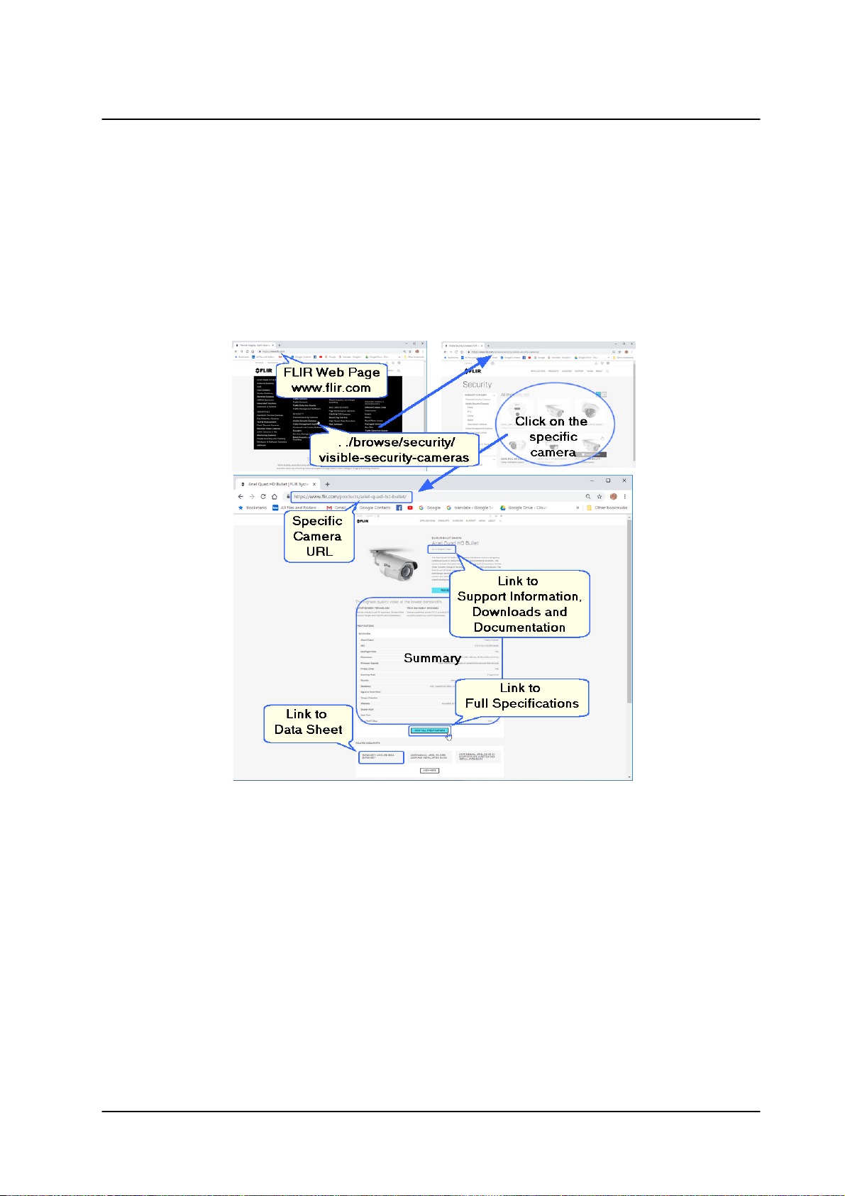
1.1 Accessing General Camera Information
Detailed Camera information is available on the FLIR website, accessible by navigating
to /Products, /Security, /Visible Security Cameras, and selecting the required camera.
CM-3304/CM-3308 User and Installation Guide
March 10, 20196
Page 13
Introduction
·
Progressive scan 4MP or
8MP sensor
·
Three streams
·
Audio line in and alarm in
·
H.265, H.264 and MJPEG
compression
·
64-20,480 kbps bit rate
·
Built-in web server
·
Two regions of interest
·
8 privacy zones
·
Tampering detection and
notifications
·
Record snapshots and video
on 128GB microSD card
(not included)
·
Send snapshots on alarm
to FTP or 10 email
addresses
·
Motion detection event-driven
alarms
·
Two encoder streams
·
Remote viewing via RTSP
on media players
·
Basic Video Analytics
·
SNMP v1/v2c/v3 and SNMP
traps
·
802.1X and SSL/TLS
security protocols
·
Powered by 802.3af PoE
·
Backlight and highlight
compensation
·
Gamma correction
·
UPnP support
·
Electronic day/night (ICR)
·
Digital WDR
·
White balance
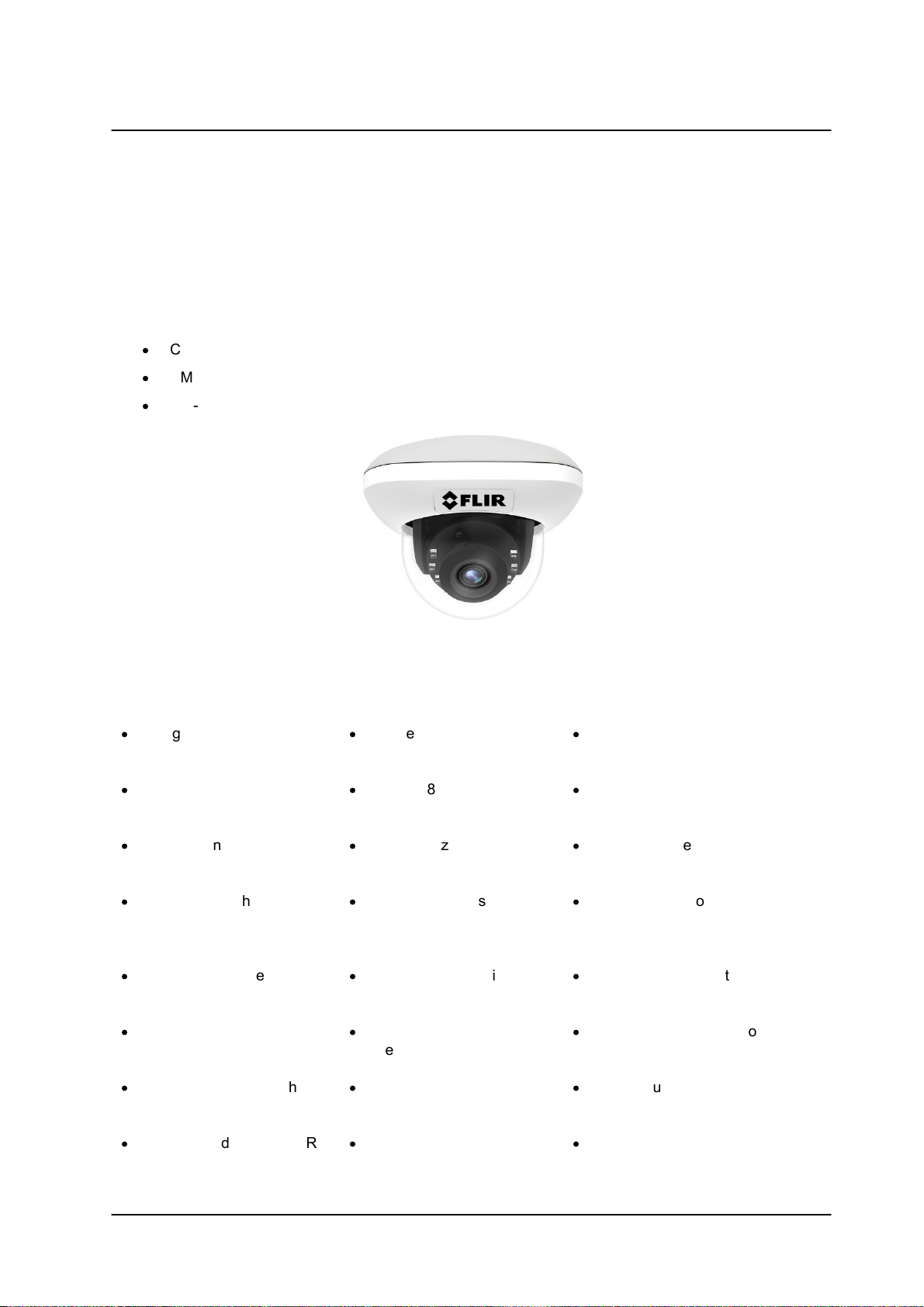
2 Introduction
This User and Installation Guide is intended to help you physically install, configure settings for and
operate the CM-330X indoor/outdoor mini-dome IP camera. The unit is a day/night camera with a 4MP (CM-
3304) or 8MP (CM-3308) sensor and includes an IR cut filte, audio line in and alarm in. It supports four
streams: 4MP or 8MP, Full HD 1080p, HD 720p, and D1 with H.265, H.264 or MJPEG compression. The
camera is powered by an 802.3af Power over Ethernet (PoE) connection. Three models are available:
·
CM-3304-11-I includes a 1/2.9” BSI CMOS Vari-focal 2.8~8.5mm, 100° HFOV, F1.2, D/N lens
·
CM-3304-21-I includes a 1/2.9” BSI CMOS Vari-focal 9~22mm, F1.5, D/N lens
·
CM-3308-11-1 includes a 1/2.5” BSI CMOS, Vari-focal 3.4~9mm, 100° HFOV, F1.5, D/N lens
2.1 Features
Figure 1: CM-330X Mini-Dome Camera
CM-3304/CM-3308 User and Installation Guide
7March 10, 2019
Page 14

Introduction
·
ONVIF support
·
Infrared LED illuminator
·
3DNR image noise reduction
·
IP67 enclosure with IK10
vandal-proof protection
·
Built-in heater
·
Low-lux mode without IR
·
Up to 9 users
Item
CM-3304
CM-3308
CM-330x Minidome Camera
1pc
1pc
Tapping Screws (TP4 25mm)
2pcs
2pcs
Tapping Screws (TP4 32mm)
2pcs
2pcs
M4 Screw (25mm)
2pcs
2pcs
Plastic anchors
2pcs
2pcs
T20 Torx wrench
1pc
1pc
Drill template
1pc
1pc
Water proof cap
1pc
1pc
Desiccants
1pc
1pc
Desiccants QIG
1pc
1pc
X type bracket
1pc
1pc
Quick Installation Guide
1pc
1pc
2.2 Package Contents
The unit package contains the following items:
Note: For all current documentation, see Accessing Camera Information from the Web
Related Information:
·
CM-330X Quick Installation Guide
·
CM-CAPX-31 Pendant Mount
·
CM-BKBX-31 Mini-Dome Conduit Back Box Kit
·
CM-4S-31 Adapter Plate Junction Box
·
CM-330X Desiccant Instructions
·
DNA 2.2 User Manual
CM-3304/CM-3308 User and Installation Guide
March 10, 20198
Page 15
3 Hardware Description
3.1 Dimensions
·
CM-3304 Camera Dimensions
·
CM-3308 Varifocal Camera Dimensions
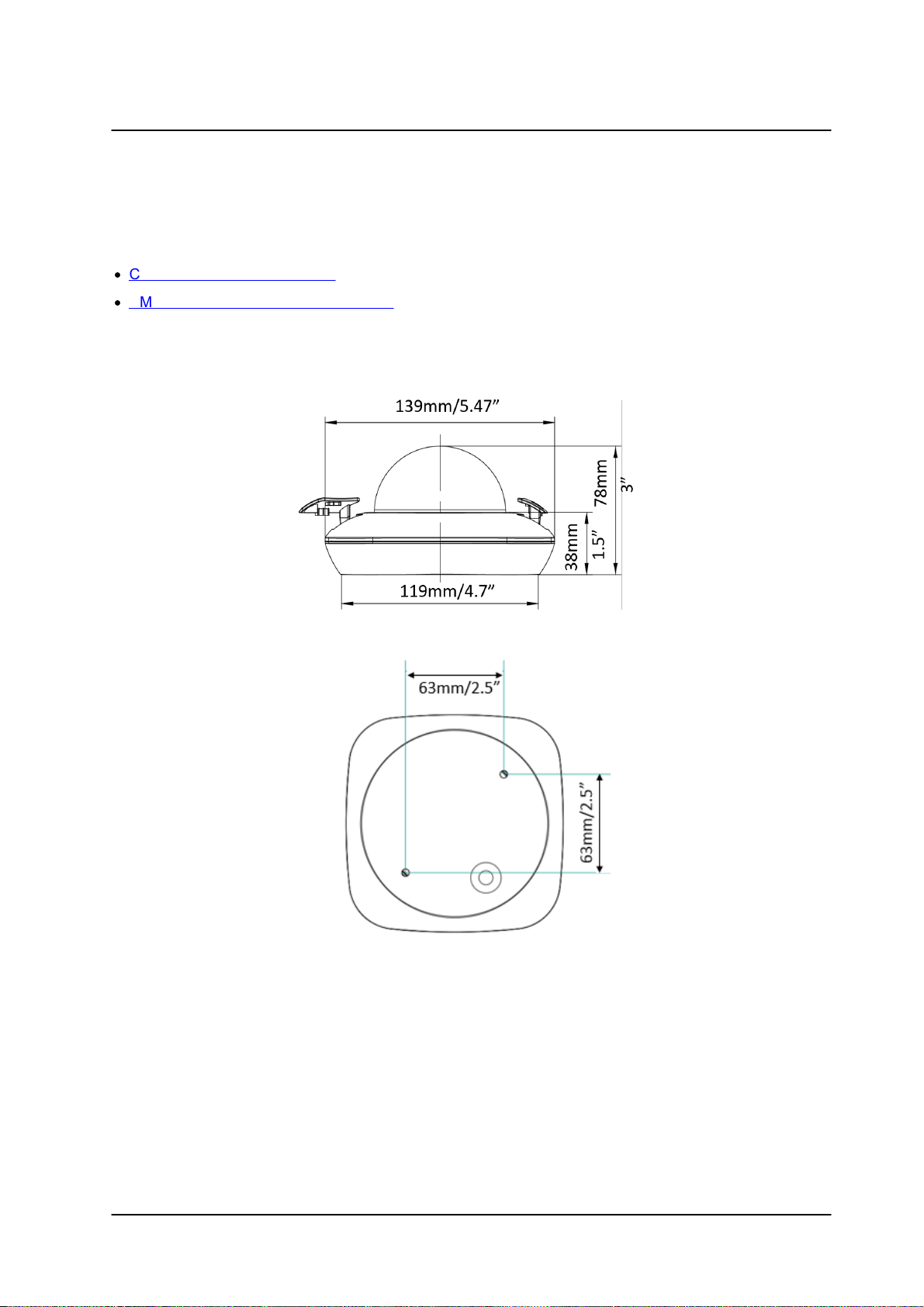
3.1.1 CM-3304 Camera Dimensions
Following are the CM-3304 camera dimensions:
Hardware Description
Figure 2: Fixed Focal Side Dimensions
Figure 3: Base Dimensions
The CM-3304 camera includes a network cable with an RJ45 Ethernet jack. The cable includes an LED
that flashes green to indicate power on and network activity. The link is not illuminated if there is no
network activity.
CM-3304/CM-3308 User and Installation Guide
9March 10, 2019
Page 16
Hardware Description
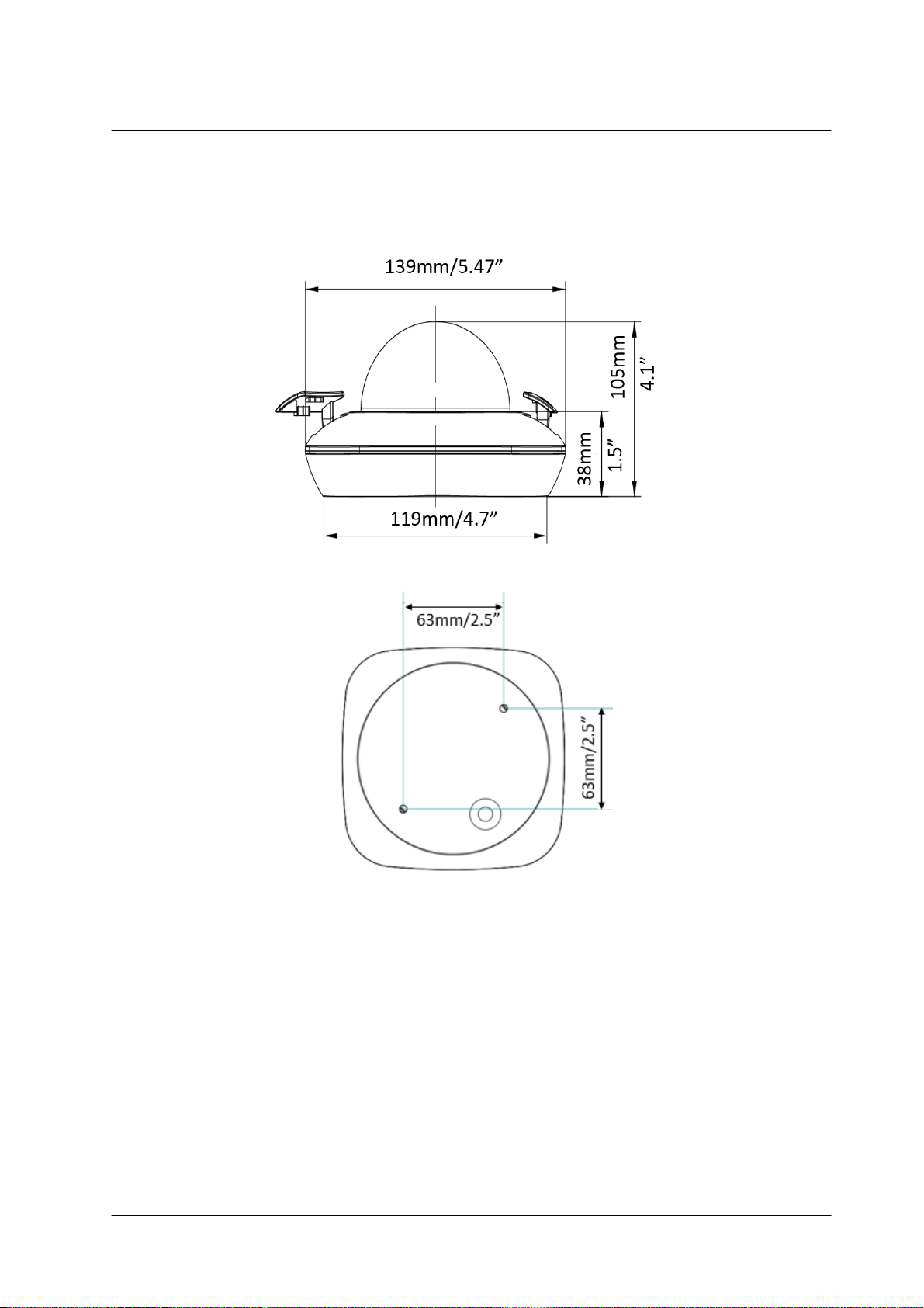
3.1.2 CM-3308 Varifocal Camera Dimensions
Following are the CM-3308 motorized varifocal camera’s dimensions.
Figure 4: Side Dimensions
Figure 5: Varifocal Base Dimensions
CM-3304/CM-3308 User and Installation Guide
March 10, 201910
Page 17
Hardware Description
Item
Minimum System Requirement
Personal Computer
Intel® Pentium® IV, 2.4GHz or higher with >1GB RAM
Monitor display with minimum 1024 x 768 resolution
(NVIDIA GeForce 6 Series or ATI Mobility Radeon 9500)
Operating System
Microsoft Windows XP SP1 and above; Windows 7, 8, and 8.1
Windows Server 2003, Windows Server 2008 (32-bit)
Web Browser
Microsoft Internet Explorer 10 and above (32-bit version)
Network Card
10Base-T (10 Mbps) or 100Base-TX (100 Mbps) operation
Viewer
ActiveX control plug-in for Microsoft Internet Explorer
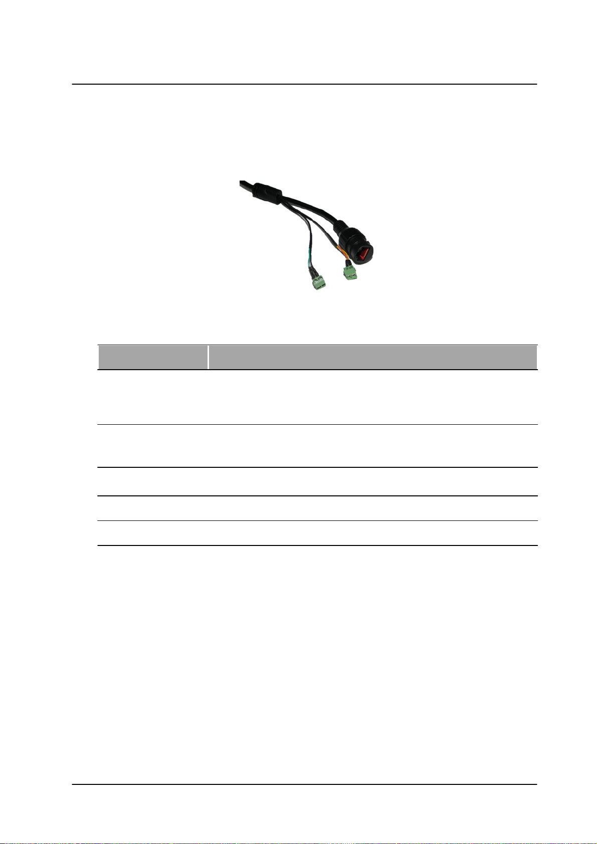
The CM-3308 camera includes a built-in system cable that includes an RJ-45 Ethernet jack and two (2)
two-wire leads that provide an audio-in connection and an alarm-in connection. The cable includes an LED
that flashes green to indicate power on and network activity. The link is not illuminated if there is no
network activity.
Figure 6: CM-330X System Cable
3.2 System Requirements
CM-3304/CM-3308 User and Installation Guide
11March 10, 2019
Page 18
Installing and Connecting the Camera
Caution:
To avoid damage from overheating or unit failure, assure that there is sufficient
temperature regulation to support the unit’s requirements (cooling/heating). Operating
temperature should be kept in the range -40° to 50°C (-40° to 122°F), with no more than
90% non-condensing humidity.
Attention:
Afin d'éviter tout dommage dû à une surchauffe ou toute panne de l'unité, assurez-vous
que la régulation de température est suffisante pour répondre aux exigences de l'unité
(refroidissement/chauffage). La température de fonctionnement doit être maintenue
dans la plage (-40° à 50°C/-40° à 122°F), sans condensation d'humidité supérieur à
90%.
4 Installing and Connecting the Camera
This section describes how to install and connect the unit. It includes the following topics:
·
Pre-Installation Checklist
·
Outdoor Mounting Recommendations
·
Mounting Instructions
·
Powering the Camera
·
Connecting the Camera to the Network
·
Resetting the Camera
4.1 Pre-Installation Checklist
Before installing the unit, make sure that:
·
Instructions in the Document Scope and Purpose section are followed.
·
All related equipment is powered off during the installation.
·
Use best security practices to design and maintain secured camera access, communications
infrastructure, tamper-proof outdoor boxes, etc.
·
All electrical work must be performed in accordance with local regulatory requirements.
4.2 Outdoor Mounting Recommendations
Following are additional considerations for outdoor installation:
·
For outside wiring installation, always use weatherproof equipment, such as boxes, receptacles,
connectors, etc.
·
For electrical wiring, use the properly rated sheathed cables for conditions to which the cable will
be exposed (for example, moisture, heat, UV, physical requirements, etc.).
CM-3304/CM-3308 User and Installation Guide
March 10, 201912
Page 19
Installing and Connecting the Camera
·
Plan ahead to determine where to install infrastructure weatherproof equipment. Whenever
possible, ground components to an outdoor ground.
4.3 Mounting Instructions
Follow the instructions in Installation Guides listed in the Related Information section of the Package
Contents section.
To mount the camera in the ceiling
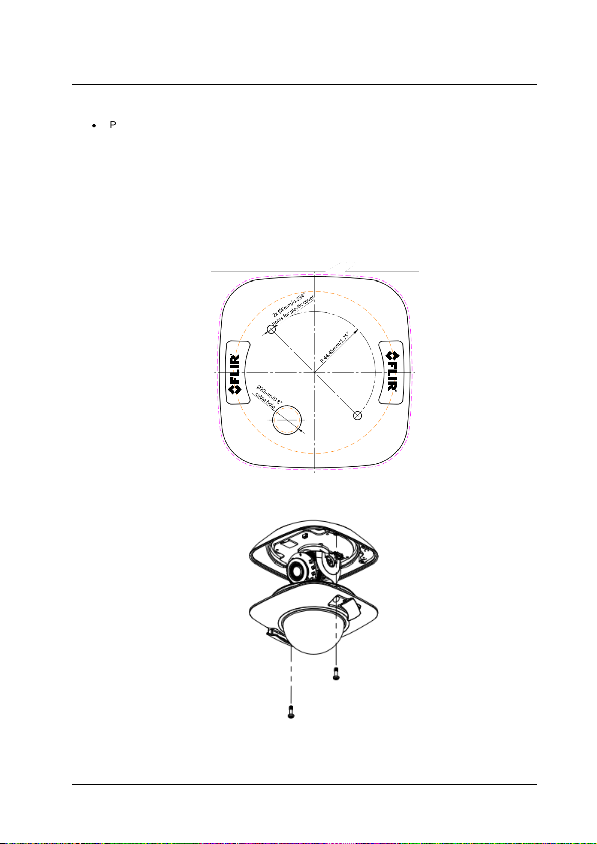
1. Drill the screw holes on the surface with the supplied drilling template. If you need to route the
cables from the bottom of the camera, cut a cable hole in the surface.
Figure 7: Drill Template
2. Remove the lower dome by loosening the set screws with the supplied Torx wrench
Figure 8: Open the Dome Cover
CM-3304/CM-3308 User and Installation Guide
13March 10, 2019
Page 20
Installing and Connecting the Camera
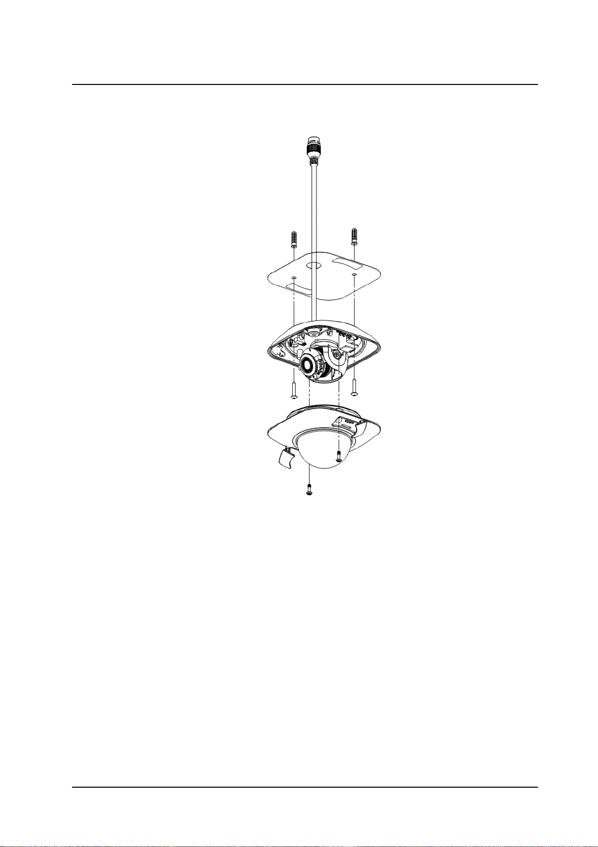
3. Fix the mounting base on the surface with screws.
Figure 9: Dome Ceiling Installation
CM-3304/CM-3308 User and Installation Guide
March 10, 201914
Page 21
Installing and Connecting the Camera
Note: CM-330X units require the spacer when using the CM-RCSD-G2 recessed
mount. Use the mechanical screws included with the spacer for proper mounting.
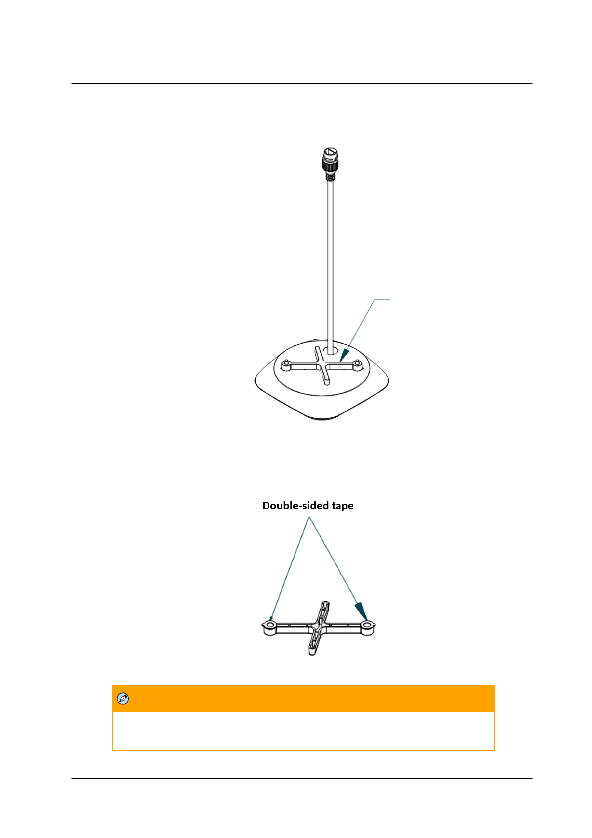
4. If you are mounting the camera on a solid surface, attach the included spacer to the base of the
camera.
Figure 10: Spacer Attached to Camera Base
5. Align the holes of the spacer with the holes in the base of the camera. Use the appropriate
mounting hardware for your surface.
Figure 11: Align Spacer
CM-3304/CM-3308 User and Installation Guide
15March 10, 2019
Page 22
Installing and Connecting the Camera
Tip: Adjust the panning position and tilting position to get the desired surveillance angle.
Caution:
1. This product must be connected only to a PoE network.
2. The PoE supply’s rated output is 48VDC, 0.2A.
3. If the camera is installed for outdoor use, the PoE supply must be installed with proper
weatherproofing.
4. As a Listed Power Unit, the PoE should be marked as “LPS” or “Limited Power Source”.
5. This product shall be installed by a qualified service person. Installation shall conform to all local
codes.
Attention:
6. Ce produit doit être connecté uniquement à un réseau PoE.
7. La puissance nominale de l'alimentation PoE est 48VDC, 0.2A.
8. Si la caméra est installée pour une utilisation extérieure, l'alimentation PoE doit être installé
avec l'étanchéisation appropriée.
9. Comme une unité d'alimentation «Listed», le PoE doit être marqué comme «LPS» ou «Limited
Power Source".
6. Loosen the tilt lock screws, adjust the tilting position in a range of 65 degrees, and tighten the tilt
lock screws. Rotate the black liner to adjust the panning position in a range of 360 degrees until
getting the desired surveillance angle.
7. Reinstall the lower dome and tighten the screws.
4.4 Powering the Camera
The camera is powered by an 802.3af PoE (Class 3) connection over the unit’s network cable.
Figure 12: Power Connection
CM-3304/CM-3308 User and Installation Guide
March 10, 201916
Page 23
Installing and Connecting the Camera
10. Ce produit doit être installé par un technicien qualifié. L'installation doit se conformer à tous les
codes locaux.
Note:
1. It is possible to set the IP address without changing the subnet.
2. The unit and the PC must be physically connected on the same network
segment.
3. The PC browser version must be 32-bit Internet Explorer (IE 10 and above).
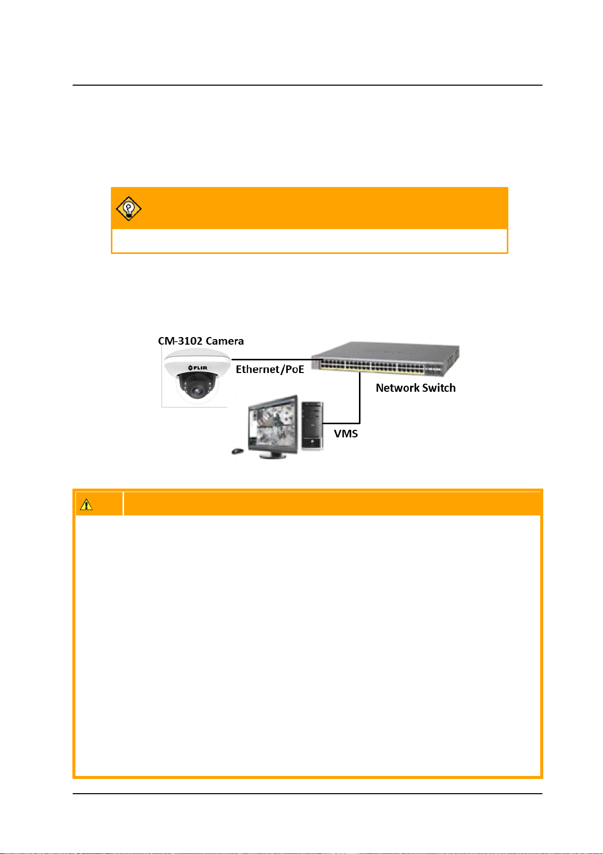
4.4.1 Connecting the Camera to the Network
To view and configure the camera via a LAN, you must attach the camera via the network switch or router
to the same subnet (network segment or VLAN) as the computer that manages the unit. It is
recommended to use FLIR’s DNA utility to search for and change the camera’s initial IP address.
4.4.2 Configuring the Unit’s Initial IP Address
Use the FLIR DNA utility to discover the unit on the network and to set the unit’s initial IP address.
·
If the camera is managed by FLIR’s Horizon or Meridian VMS and is configured as a DHCP server,
Horizon or Meridian automatically assigns the camera an IP address. Configure the camera with
DHCP-enabled.
·
If the camera is managed by FLIR’s Latitude VMS, manually enter its IP address in the DNA
utility.
To manage the camera using Horizon, Meridian, or on a DHCP-enabled network
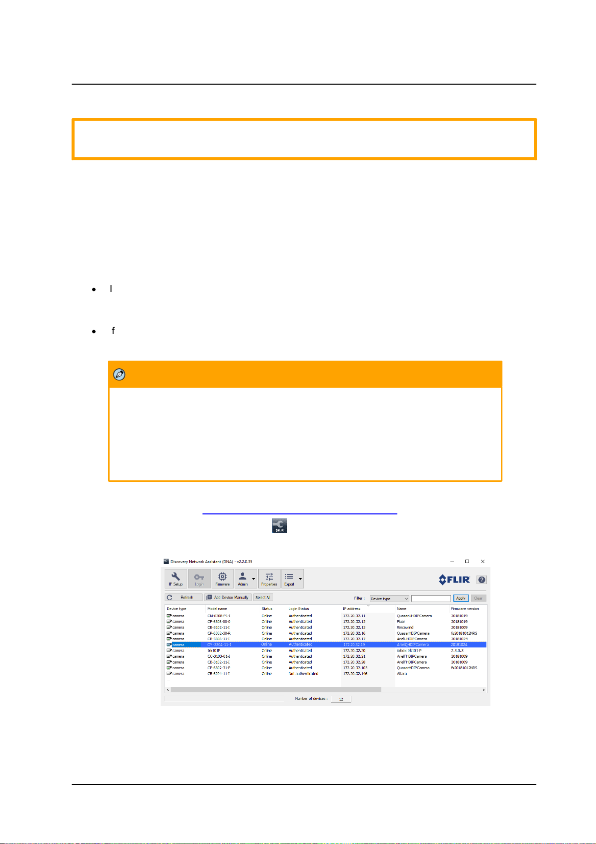
1. Download DNA. (see Accessing Camera Information from the Web).
2. Run the dna.exe file by clicking the icon. The DNA application opens and the device is
displayed in the window.
Figure 13: DNA Discovery Window
CM-3304/CM-3308 User and Installation Guide
17March 10, 2019
Page 24
Installing and Connecting the Camera
Note:
The user name and password are case-sensitive.
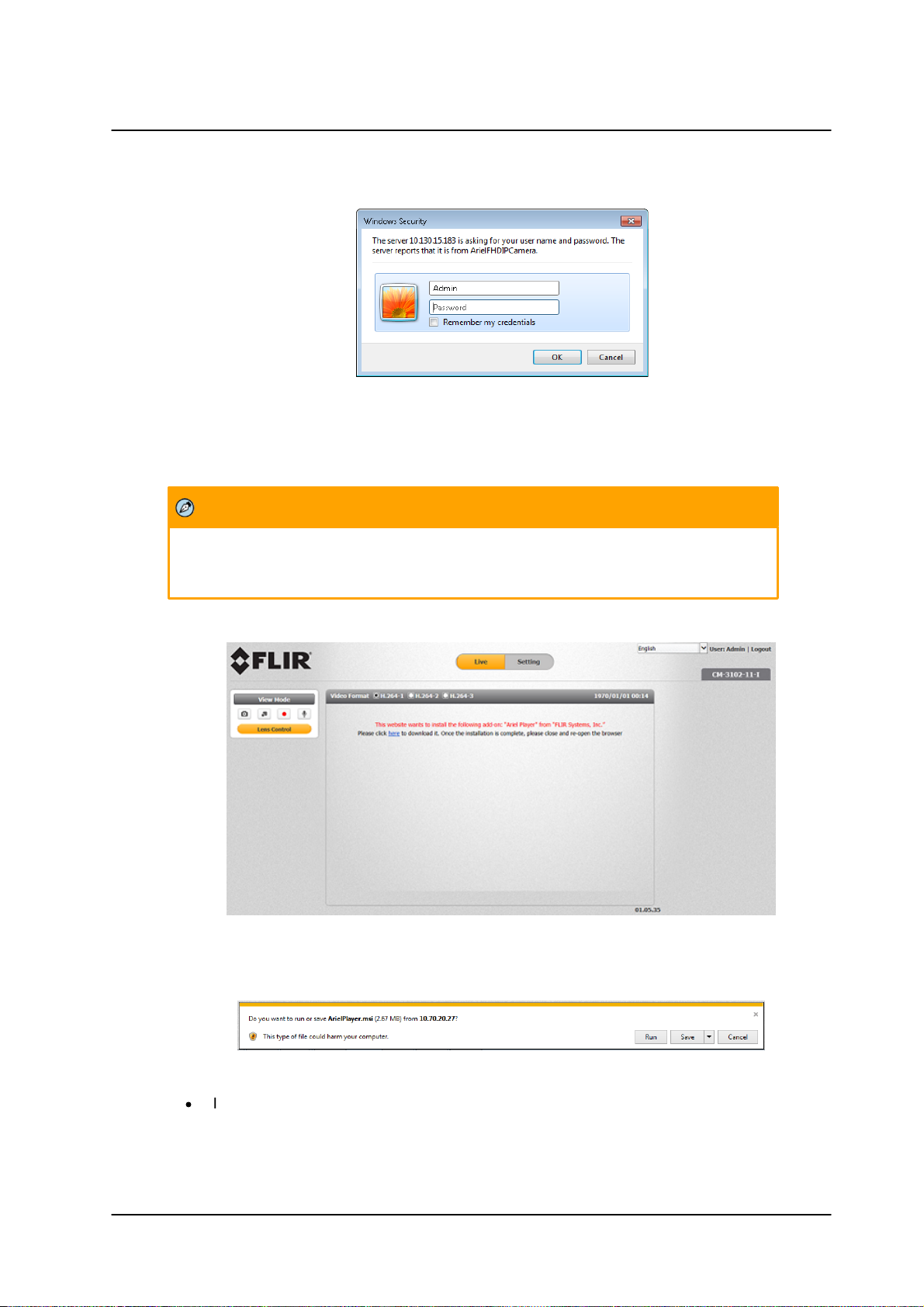
3. Click on the unit in DNA’s Discover List. The CM-330X Login window opens.
Figure 14: Login Window
4. If the camera cannot connect to a DHCP server, enter the unit’s default IP address
(192.168.0.250).
5. Enter the default User Name (Admin) and Password (1234).
6. Click Login. The camera’s web interface opens.
Figure 15: Web Interface
7. Click “here” on the screen to download the Ariel Player plug-in. The Ariel Player plug-in information
bar opens.
Figure 16: Download Ariel Player Plug-in Information Bar
·
In some cases in closed networks, Internet Explorer will not install the Ariel Player on the
client PC because it cannot verify the Ariel Player’s digital signature (because the local
certificate is out of date, invalid or missing). The following message is displayed:
CM-3304/CM-3308 User and Installation Guide
March 10, 201918
Page 25
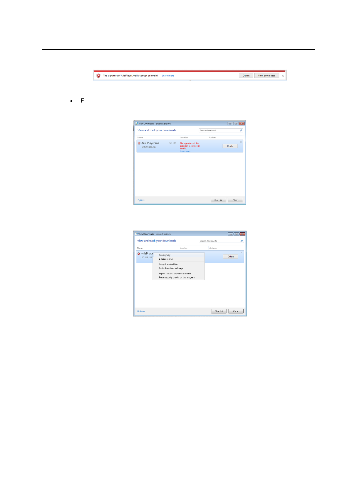
Figure 17: Corrupt/Invalid Signature
·
Follow these steps in order to install the Player:
a. Click View downloads. The View Downloads screen opens.
Installing and Connecting the Camera
Figure 18: View Downloads Screen
b. Right-click on the ArielPlayer.msi file.
Figure 19: Run Anyway Option
CM-3304/CM-3308 User and Installation Guide
19March 10, 2019
Page 26
Installing and Connecting the Camera
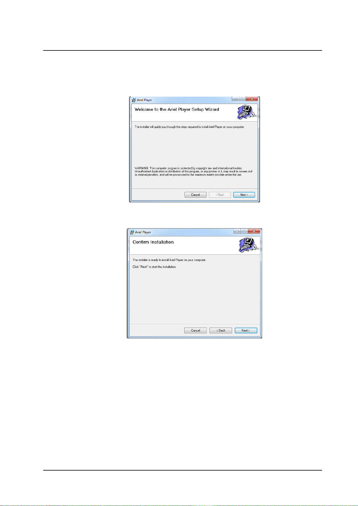
c. Select “Run anyway”. The normal installation process starts.
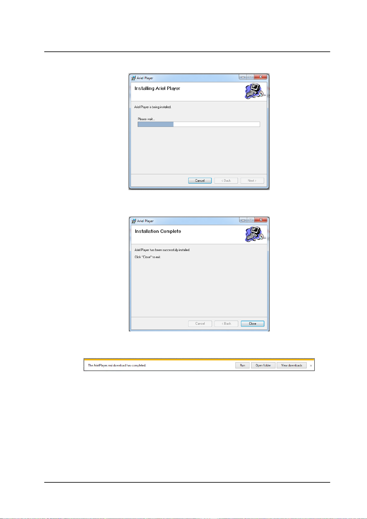
8. Click Run on the information bar to install the Ariel Player plug-in. The Windows Installer opens
and the Ariel Player Wizard dialog box is displayed.
Figure 20: Ariel Player Setup Wizard Screen 1
9. Click Next to install the Ariel Player plug-in on your PC.
Figure 21: Ariel Player Setup Wizard Screen 2
CM-3304/CM-3308 User and Installation Guide
March 10, 201920
Page 27
Installing and Connecting the Camera
Figure 22: Ariel Player Setup Wizard Screen 3
10. Click Close when the Installation Complete dialog box is displayed.
Figure 23: Ariel Player Setup Wizard Screen 4
11. After the download has completed, a second information bar opens.
Figure 24: Run Ariel Player Plug-in Information Bar
CM-3304/CM-3308 User and Installation Guide
21March 10, 2019
Page 28
Installing and Connecting the Camera
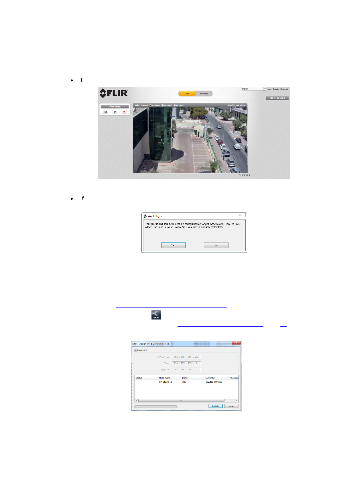
12. Click Run.
·
If you promptly close your browser, the Live View screen is displayed.
·
If you do not promptly close your browser, a dialog box opens, prompting you
to restart your computer, in order to save changes.
Figure 25: Live View Screen
Figure 26: Ariel Player Restart System Dialog Box
d. Click Yes. The computer reboots and the Rebooting Completed message
appears.
e. Click OK. The Live View screen is displayed.
To manage the camera using Latitude or on a network with static IP configuration
1. Download DNA. (see Accessing Camera Information from the Web)..
2. Run the dna.exe file by clicking the icon. The DNA application opens and the device is
displayed in the DNA Discovery window. See Figure 13: DNA Discovery Window (page 20).
3. Select the unit by right-clicking it. The DNA - Assign IP window is displayed.
Figure 27: DNA Assign IP - Use DHCP Screen
4. Uncheck Use DHCP.
CM-3304/CM-3308 User and Installation Guide
March 10, 201922
Page 29

Installing and Connecting the Camera
Note:
The user name and password are case-sensitive.
5. Enter the unit’s default IP address (192.168.0.250), Subnet mask, and Gateway IP address in the
respective field.
6. Click Update. The unit reboots with the new settings.
7. Click on the unit in DNA’s Discover List. The camera’s Login window opens.
See Figure 14: Login Window (page 21).
8. Enter the default User Name (Admin) and Password (1234).
9. Click Login. The camera’s web interface opens. See Figure 15: Web Interface (page 21).
10. Click the on-screen message to install the Ariel Player plug-in. The Ariel Player Plug-in message
is displayed. See Figure 16: Download Ariel Player Plug-in Information Bar (page 21).
CM-3304/CM-3308 User and Installation Guide
23March 10, 2019
Page 30
Installing and Connecting the Camera
4.4.3 Inserting and Configuring the microSD Card
A microSD card (not supplied) (Min recommended 4GB, up to 128GB, Class 10) must be inserted in the
camera in order to locally store a snapshot or recording triggered by an event. The microSD card slot is
located on a printed circuit board inside the camera housing.
To install a microSD card:
1. After removing the camera's cover, insert a microSDXC card in the card slot.
2. Be sure that a new desiccant is inserted inside the enclosure.
3. Replace the cover and screw the enclosure shut.
4. Verify that the card status is displayed as Mounted in the System > Events Handler > SD Card
screen.
5. Configure the camera to store snapshots and recordings from the System > Events Source
screens.
CM-3304/CM-3308 User and Installation Guide
March 10, 201924
Page 31

Installing and Connecting the Camera
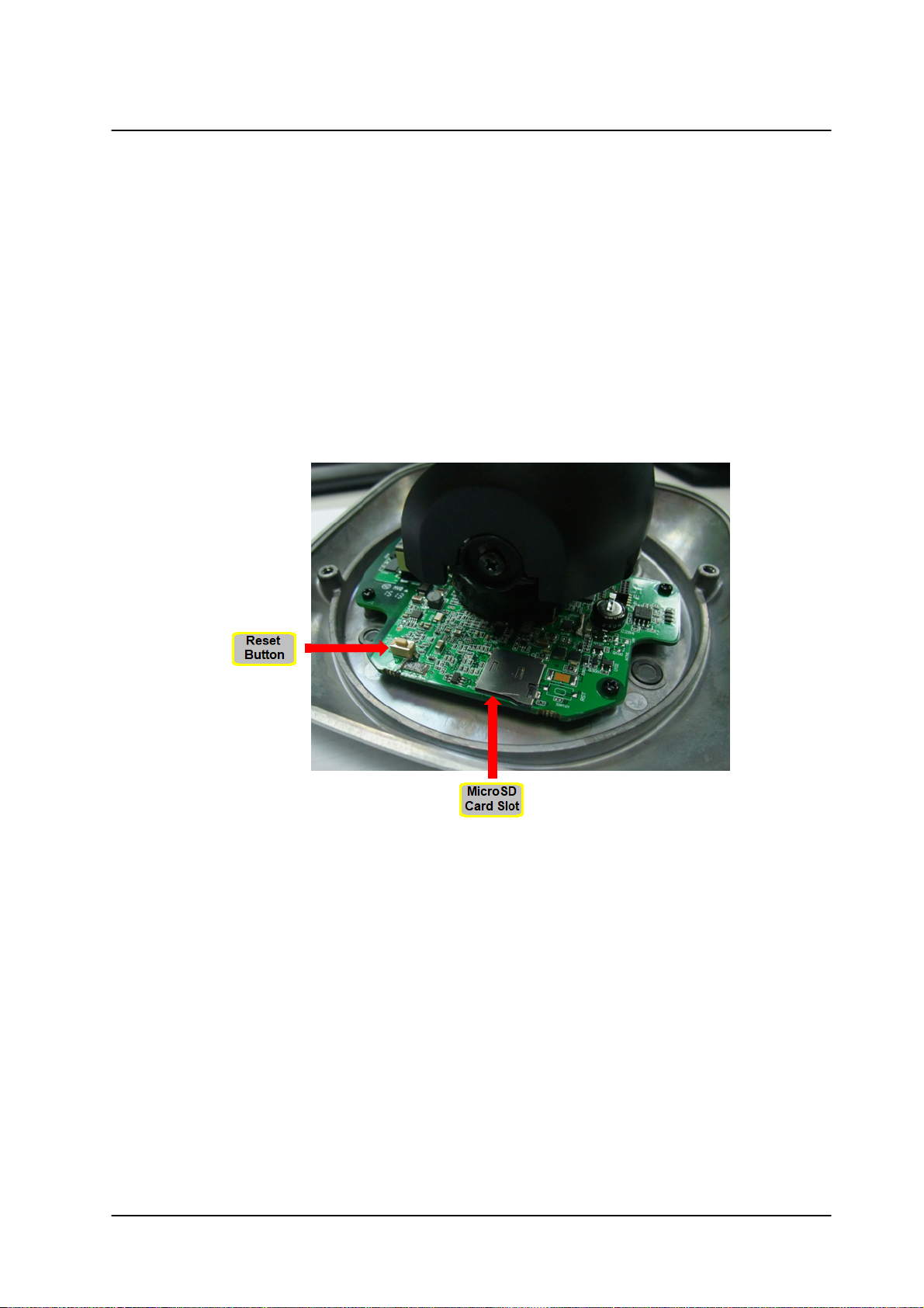
4.4.4 Resetting the Camera
The camera includes a reset button, which is located on the camera’s printed circuit board (PCB), along
with the camera’s microSD card slot.
Figure 28: Camera Reset Button/MicroSD Slot
To reboot the camera (Partial Reset)
Press the Default button for approximately five seconds. The unit reboots.
Configured settings are saved.
To restore factory defaults (Full Reset)
Press the Default button continuously for 30 seconds.
The unit restores factory defaults, including the original network settings.
If a Basic Video Analytics license was in use, it will need to be re-loaded.
.
CM-3304/CM-3308 User and Installation Guide
25March 10, 2019
Page 32

Accessing the CM-330X via a Web Browser
Note:
1. When the HTTPS feature is enabled, by default the system uses HTTPS login
mode (e.g., https://192.168.0.250) when you enter the IP address.
2. If you want to use HTTP mode to log into the device, enter http://IP address
(e.g., http:// 192.168.0.250).
Note:
The user name and password are case-sensitive.
5 Accessing the CM-330X via a Web
Browser
The CM-330X includes a web interface that enables it to be configured and operated from a web browser
(32-bit version of Internet Explorer 10 and above).
To access the unit via the web browser
1. Open Internet Explorer.
2. Enter the unit’s IP address in the browser’s address bar.
3. Press the ENTER key on your PC keyboard. The unit’s Login window is displayed.
See Figure 14: Login Window (page 21).
4. Enter the user name (default: Admin) and password (default: 1234) to log into the system. The
unit’s web interface opens. See Figure 15: Web Interface (page 21).
5. If you are using the system for the first time or you have uploaded a new firmware version, click the
message displayed on the screen to download to allow the MediaPlayer Control
Module.exe plug-in.
6. Click Allow. The Windows Installer opens and the Ariel Player Wizard dialog box is displayed.
Follow instructions in section ?5.4.2, Configuring the Unit’s Initial IP Address.
CM-3304/CM-3308 User and Installation Guide
March 10, 201926
Page 33

5.1 CM-330X Web Interface
Item
Description
Snapshot button
Click the button to take a snapshot.
Full screen button
Click the button to display the live view in full-screen mode.
To switch back to Live View mode, right-click on the screen and
click Normal Display, or press the ESC key on your keyboard.
Manual recording
button
The button indicates the recording status: red when recording is
On or gray when recording is Off .
Accessing the CM-330X via a Web Browser
Figure 30: CM-330X-11-I Live View Screen with Callouts
The following information is displayed in the upper right corner of the GUI:
·
Language Bar – Select the language for the web interface: English, Arabic, Czech, Simplified
Chinese, Traditional Chinese, French, German, Hungarian, Italian, Japanese, Polish, Portuguese,
Russian, or Spanish
·
User Name – Displays the user name. By default, Admin is displayed.
·
Logout Link– Click Logout to exit the web interface.
·
Model Number – Displays the model number.
Above the Live View window, the selected video format, date and time are displayed. Below the Live
View window, the firmware version is displayed.
On the CM-330X-11-I, to the left of the Live View window, the following View Mode buttons are displayed:
CM-3304/CM-3308 User and Installation Guide
27March 10, 2019
Page 34

Accessing the CM-330X via a Web Browser
Item
Description
Mic button
Click the Mic button to enable the local site to talk to the
remote site. This function is available only to an Operator or
Administrator. Click the button to switch it on/off. The button
allows the user to listen to audio streaming over the web if (a)
audio is enabled and (b) if an audio event is enabled and
triggered by exceeding the threshold. See Audio (CM-330X-11-
I).
Lens Control button
Clicking the button opens the
System > Lens Control screen for controlling the lens’ zoom
and focus.
Analytics Rule Name
Displays the name of the currently configured Video Analytics
Rule
Show Analytics Rule
Overlay
Shows the configured line or area drawing configured for the
currently active Video Analytics Rule
Reset Scene
Resets the scene of a configured Video Analytics Rule. Used in
the case where the scene changed drastically such as a large
structure being removed or the camera angle changing.
From the Navigation Bar, select one of these tabs:
·
Live – Displays the Live View screen
·
Settings – Displays the Settings sidebar
5.2 Live View
To start Live View
1. From the Navigation Bar, click Live View. The Live View screen opens. See Figure 30: CM-
330X-11-I Live View Screen with Callouts.
2. Click one of the buttons listed above for the desired action from the Live View toolbar.
The following sections include the following topics:
·
Recording (page 32)
·
Capturing a Picture (page 33)
·
Viewing Live Video from a Media Player (page 34)
CM-3304/CM-3308 User and Installation Guide
March 10, 201928
Page 35

Accessing the CM-330X via a Web Browser
Note:
In order to save recordings on your PC, Internet Explorer should be run as Administrator.
Note:
In order to save snapshots on your PC, Internet Explorer should be run as Administrator.
5.2.1 Recording
Manual recordings (which are triggered from the Live View screen) are stored on the PC.
To start recording a Live View scene
1. Click the red Manual Recording icon on the toolbar. The camera starts recording. A red dot
is displayed in the upper right corner of the Live View window, under the date and time display.
2. Select the directory and folder to save the video, which is an .avi file.
3. Click the icon to stop recording. The icon turns gray .
To playback a Live View recording
4. Open the folder on the PC where the recording is stored.
5. Select the file.
Recordings that are triggered by events (such as motion detection) are stored on the camera’s microSD
card, which can store up to128GB of data. The card is not included.
To view a triggered event recording
6. In your browser, enter the camera’s FTP address (ftp://camera_ip/).
7. Enter the Admin user name and password.
8. Open the folder for the event according to the type of event (motion detection, tampering, etc.).
Files are displayed chronologically according to most recent date.
9. Select the file.
5.2.2 Capturing a Picture
It is possible to capture a picture as a snapshot in Live View mode and save it on your PC as a .jpeg or
.png file image.
To capture a snapshot in Live View mode
1. In Live View mode, click the Snapshot button on the toolbar to capture the live pictures.
To view a Live View snapshot
2. Open the folder on the PC where the snapshot is stored.
3. Select the file.
CM-3304/CM-3308 User and Installation Guide
29March 10, 2019
Page 36

Accessing the CM-330X via a Web Browser
Snapshots that are triggered by events (such as motion detection) are stored on the camera’s microSD
card, which can store up to 128GB of data. The card is not included.
To view a triggered event snapshot
4. In your browser, enter the camera’s FTP address (ftp://camera_ip/).
5. Enter the Admin user name and password.
6. Open the folder for the event according to the type of event (motion detection, tampering, etc.).
Files are displayed chronologically according to most recent date.
7. Select the file.
5.2.3 Viewing Live Video from a Media Player
The Live View main stream and sub-stream can be viewed with a media player, such as VLC (download
from http://www.videolan.org/vlc/index.html). Streams can be viewed for the three channels and two video
encoding formats (H.264 and MJPEG).
The camera supports sending unicast and multicast streams via the RTSP protocol. Unicast streams
include the suffix “stream” followed by the stream number without a space. Multicast streams include the
suffix “streamXm”, where “X” is the stream number (1, 2 or 3).
To view a media stream with VLC
1. Open VLC.
2. From the Media tab, select Open Network Stream. The Open Media screen is displayed.
Figure 31: VLC Open Media Screen
3. In the Network tab, enter the URL for the stream in the address bar:
·
The syntax for entering the URL in the media player for the main stream is:
rtsp://(camera IP address)/(Unicast stream 1) or (Multicast stream 1). For example,
rtsp://192.168.0.250/stream1 for a unicast stream.
·
The syntax for entering the URL in the media player for the second stream is: rtsp://(camera
IP address)/(Unicast stream 2) or (Multicast stream 2). For example, rtsp://
192.168.0.250/stream2 for a unicast stream.
CM-3304/CM-3308 User and Installation Guide
March 10, 201930
Page 37

Accessing the CM-330X via a Web Browser
Note:
1. It is also possible to change the syntax on the RTSP page,
although this is not recommended if the camera is attached to a
VMS.
2. Verify that the resolution entered in URL string agree with the
resolution set in the Streaming > Video Settings screen.
·
The syntax for entering the URL in the media player for the third stream is:
rtsp://(camera IP address)/(Unicast stream 3) or (Multicast stream 3). For example, rtsp://
192.168.0.250/stream3m for a multicast stream.
4. Click Play. The video stream is displayed in the media player. If available, audio will also be
streamed.
Figure 32: Media Player Screen
5.2.4 Basic Video Analytics
Notes:
1. When Motion Detection is configured, Basic Video Analytics is disabled.
2. Basic Video Analytics is only enabled when the appropriate Camera License has been uploaded to the
camera.
When Basic Basic Video Analytics is enabled, the configured rule will display on the left side of the Live
View page. This section will show the current active rule, and provides the ability to see the configured
overlay drawing and to reset the scene.
CM-3304/CM-3308 User and Installation Guide
31March 10, 2019
Page 38

Accessing the CM-330X via a Web Browser
Counting
Border Line
Loitering
Area Protection
Object Removal
Object Dropped
Under the "Video Analytics" heading is the name of the current active analytic rule. The rule options are:
When "Draw Analytics Overlay" is checked, it will show the configured drawing for that rule.
The rule cannot be edited from the Live page. In order to edit the configuration, the user must navigate to
Settings > System > Video Analytics and choose the desired rule.
Reset Scene
CM-3304/CM-3308 User and Installation Guide
March 10, 201932
Page 39

Accessing the CM-330X via a Web Browser
Figure 34: System Menu
(Default - No Camera Analytics License installed)
Figure 35: System Menu - (Camera Analytics License installed)
Lens Control
Basic
Configuration
User
Accounts
Network
Events
Source
Events
Handler
Video
Analytics
Clicking Reset Scene will relearn the scene and the background in case the scene has changed or the
camera has been moved.
5.3 Settings
Device and client PC parameters are set from the Settings tab in the navigation bar. Upon clicking
Settings, the Settings menu is displayed in the sidebar. Three sections are displayed: System,
Streaming, and Camera.
Figure 33: Unexpanded Sidebar
5.3.1 System Tab
The System tab is used for configuring essential system settings. Click the System tab to expand the
menu.
Click the link to open the tabs for the various functions:
CM-3304/CM-3308 User and Installation Guide
33March 10, 2019
Page 40

Accessing the CM-330X via a Web Browser
Note:
If the Auto Focus function does not produce a clear picture, do the following:
1. Click Reset in the Reset Lens section.
2. Click Start in the Focus Control section. The image refocuses.
3. Continue with the lens setup procedure.
5.3.1.1 Lens Control
The Lens Control screen enables control of the lens zoom and focus functions.
Figure 36: CM-330X-11-I Lens Control Screen
To set the zoom control
1. In the Zoom Control section, move the slider to the desired zoom between Wide (1.00) to Tele
(3.00).
To set Auto Focus
2. In the Focus Control section, click Start. Auto Focus is adjusted.
CM-3304/CM-3308 User and Installation Guide
March 10, 201934
Page 41

Accessing the CM-330X via a Web Browser
Note:
After clicking the Restore Position Start button, it is necessary to click the One-Push
AF Start button in the Focus Control section to refocus the lens.
Date & Time
Audio
Firmware
Basic Operations
OSD
To manually set the focus
3. In the Focus Control section, move the slider to the desired focus between Far (1) to Near (100).
4. From the Step drop-down list, select the number of steps to set the focus: 1, 2, 4, 8, 16, 32, 64, or
128.
To set the Zoom Trigger Control
5. In the Zoom Trigger Control section, from the Zoom Trigger drop-down list, select ON or OFF. This
setting determines if the camera will automatically focus itself after the zoom has been changed.
To revert to the previous settings
6. In the Restore Position section, click Start. The previous settings are restored.
5.3.1.2 Basic Configuration
The Basic Configuration tab includes the following screens:
5.3.1.2.1 Date & Time
The current time is displayed in the Current Camera Time text box. To set the date and time, select Basic
Configuration > Date & Time. The Date & Time screen is displayed.
Figure 37: Date & Time Screen
CM-3304/CM-3308 User and Installation Guide
35March 10, 2019
Page 42
Accessing the CM-330X via a Web Browser
To change the date and time
1. Select one of the following options
·
Manual Settings – Enter the date and time in the respective field.
·
Synchronize with PC – Enter the date and time in the respective field.
·
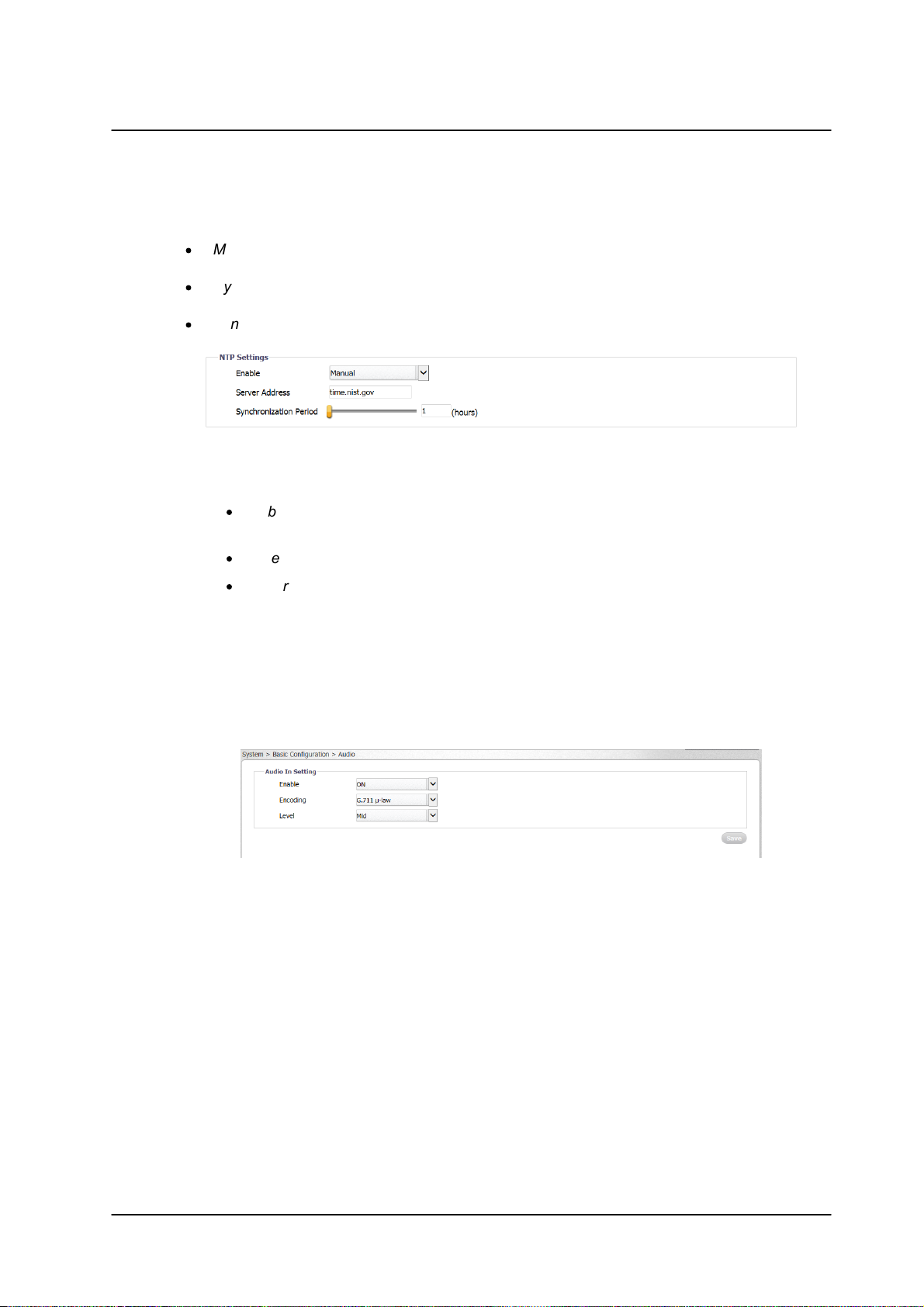
Synchronize with NTP Server – Selecting this option opens the NTP Settings section:
a. Enter the following details in the NTP Setting section:
·
Enable – From the drop-down list, select Manual to set the NTP server manually,
or From DHCP Server to set the time according to the network DHCP server.
Figure 38: NTP Setting Section
·
Server Address – Enter the IP address for the NTP server.
·
Synchronization Period – Select a number between 1-24 for the frequency (in
number of hours) that the camera will synchronize with the NTP time server (i.e.,
every one hour, every two hours, etc.).
2. In the Time Zone Setting section, from the Area drop-down list, select your local time zone.
3. Click Save. The new time is displayed in the Current Camera Time text box.
5.3.1.2.2 Audio
The Audio screen is used for configuring Audio In settings.
Figure 39: Basic Configuration > Audio Screen
To enable audio settings
1. From the Enable drop-down list, select ON.
2. From the Encoding drop-down list, select G.711 a-law, G.711 µ -law, or AAC. The default is AAC.
3. From the Level drop-down list, select High, Mid, or Low.
CM-3304/CM-3308 User and Installation Guide
March 10, 201936
Page 43

Accessing the CM-330X via a Web Browser
Note:
If you are upgrading from the GA firmware version 01.05.32 or 01.05.32.5 to version
01,05.37.4 or higher, you must update the .bin file from DNA version 2.1.2.4 or higher.
5.3.1.2.3 Firmware
The Firmware screen displays and is used to update the system firmware, and to display the hardware version, product name (model number), product serial number, and product MAC address. To access the Firmware screen, select Basic Configuration > Firmware.
Figure 40: Firmware Screen
To update system firmware
1. Click Browse to locate the firmware file.
2. Select the file. The file name is displayed (for example, ArielFHD_20160308.tar).
3. Click Upgrade. The upgrade process takes about three minutes. After the firmware has upgraded
successfully, the camera reboots. The following dialog box is displayed:
Figure 41: Rebooting Complete Dialog Box
4. Click OK. The Live screen opens.
5. When the Internet Explorer dialog box asks you to close the window, click Yes. The window
closes.
6. Open a new window and enter the camera’s URL. The Login window opens. See Figure 14: Login
Window.
7. Enter your user credentials and log into the camera. The new firmware version is displayed in the
Firmware Version text box.
CM-3304/CM-3308 User and Installation Guide
37March 10, 2019
Page 44

Accessing the CM-330X via a Web Browser
Caution:
Selecting Full factory defaults causes the camera to lose all network settings.
Attention:
Sélection par Défaut Complet d'Usine entraîne la caméra de perdre tous les paramètres réseau.
5.3.1.2.4 Basic Operations
The Basic Operations screen is used for the following functions:
·
Setting the TV format
·
Importing settings from another unit
·
Exporting settings to another unit
·
Rebooting the camera
·
Restoring partial factory defaults
·
Restoring full factory defaults
Figure 42: Basic Operations Screen
Click Reboot to save configured settings.
Click Partial factory defaults to restore factory defaults, but retain network settings (IP address, netmask
address, and gateway address), TV format, and image rotation settings. If a Basic Video Analytics license
was in use, it is saved..
Click Full factory defaults to restore factory defaults, including original network settings.
To select the TV format
1. Select Basic Configuration > Basic Operations. The Basic Operations screen is displayed.
2. From the drop-down list, select NTSC or PAL. The default is NTSC.
To import a setting
3. Click Browse to select the file.
4. Click Import to upload the file.
To export a setting
5. Click Export. An information bar opens.
CM-3304/CM-3308 User and Installation Guide
March 10, 201938
Page 45

Accessing the CM-330X via a Web Browser
Note:
Since the unit’s IP address might change when restoring full factory defaults, it is
recommended to use DNA to discover the unit after rebooting.
Note:
Since the unit’s IP address might change when restoring full factory defaults, it is
recommended to use DNA to discover the unit after rebooting.
6. Click Save in the information bar to save the file.
To reboot the camera
7. Click Reboot. The camera reboots. After the reboot finishes, a popup window opens with the
message “Rebooting complete”.
8. Click OK. A dialog box opens, requesting you to close the tab in your browser.
9. Close the tab.
10. Open a new tab in your browser, and re-enter the camera’s IP address. The camera’s Login
window opens.
11. Enter your login credentials. The camera’s home page opens.
To restore partial factory defaults
12. Click Partial factory defaults. The camera reboots. After the reboot finishes, a popup window
opens with the message “Rebooting complete”.
13. Click OK. A dialog box opens, requesting you to close the tab in your browser.
14. Close the tab.
15. Open a new tab in your browser, and re-enter the camera’s IP address. The camera’s Login
window opens.
16. Enter your login credentials. The camera’s home page opens.
To restore full factory defaults
17. Click Full factory defaults. The camera reboots. After the reboot finishes, a popup window opens
with the message “Rebooting complete”.
18. Click OK. A dialog box opens, requesting you to close the tab in your browser.
19. Close the tab.
20. Open a new tab in your browser, and re-enter the camera’s IP address. The camera’s Login
window opens.
21. Enter your login credentials. The camera’s home page opens.
CM-3304/CM-3308 User and Installation Guide
39March 10, 2019
Page 46

Accessing the CM-330X via a Web Browser
5.3.1.2.5 OSD
The OSD (On-Screen Display) screen is used for setting the background color, text color, and location for
displaying the date or text in two configurable locations on the Live View window. It is also possible to set
the background color and text color to display upon the occurrence of an event.
Set the OSD location according to the following coordinates on the X and Y axes:
Figure 43: OSD Location Coordinates
To configure OSD settings
1. Select Basic Configuration > OSD. The OSD screen is displayed.
Figure 44: OSD Screen
CM-3304/CM-3308 User and Installation Guide
March 10, 201940
Page 47

Accessing the CM-330X via a Web Browser
Note:
1. User Name and Password can include up to 16 characters, including '0' to '9', 'a' to 'z', 'A' to 'Z', '.',
'-', '+', '_' and '@'.
2. The user name and password are case-sensitive.
2. In the Basic Settings section, configure the following settings for OSD-1 and OSD-2:
·
Enable – From the drop-down list, select one of the following:
·
Date – Enables you to enter the date to display.
·
Text – Enables you to enter the time to display.
·
OFF – Disables the OSD function. This is the default setting.
·
Background Color – From the drop-down list, select Black or Transparent (default setting).
·
Text Color – From the drop-down list, select Black or White (default setting).
·
Location X – Move the slider from 1 to 10 to set the location on the screen for the OSD. The
default setting is 1.
·
Location Y – Move the slider from 1 to 10 to set the location on the screen for the OSD. The
default setting is 1.
3. In the Event section, configure the following settings in case an event occurs:
·
Background Color – From the drop-down list, select Black or Transparent (default setting).
·
Text Color – From the drop-down list, select Black or White (default setting).
·
Location X – Move the slider from 1 to 10 to set the location on the screen for the OSD. The
default setting is 1.
·
Location Y – Move the slider from 1 to 10 to set the location on the screen for the OSD. The
default setting is 1.
4. Click Save when finished.
5.3.1.3 User Accounts
The User Accounts screen is used for creating, modifying, and deleting accounts; creating or modifying
credentials; and for assigning user access level (Administrator, Operator, and User). It is possible to create
up to 10 users, in addition to the default Administrator, which cannot be deleted. There can be multiple
users of all types.
Figure 45: User Accounts-Account Setting Screen
CM-3304/CM-3308 User and Installation Guide
41March 10, 2019
Page 48

Accessing the CM-330X via a Web Browser
The following privileges are assigned to each access level:
·
An Administrator has access to all screens. By default, the camera includes the Administrator
access level. There can be more than one Administrator. The default Administrator cannot be
deleted.
·
An Operator has access to the Live View screen. An Operator can change the playback stream,
take and store a snapshot, record live video and view it in full screen mode. There can be more
than one Operator.
·
A User can only view the Live View screen. A maximum of 9 Users is possible.
To modify default Administrator credentials
1. Click Modify. The Access Level dialog box opens.
Figure 46: Default Administrator Access Level Dialog Box
2. For security reasons, enter a new User Name and /or Password. The default User Name is
“Admin” and the default Password is “1234”. See the next section for conventions regarding the
User Name and Password.
3. Click Save.
To add a new operator or user
4. Click the empty row.
Figure 47: Add User Dialog Box
5. Click Add. The Access Level screen opens.
Figure 48: Empty Access Level Dialog Box
CM-3304/CM-3308 User and Installation Guide
March 10, 201942
Page 49

Accessing the CM-330X via a Web Browser
General
FTP Server
RTSP
SNMP
802.1X
IP Filter
DDNS
LDAP
SSL
6. Select Operator or User, and enter the User Name and Password.
Figure 49: Filled Access Level Dialog Box
7. Click Save. The new Operator or User name is displayed in the Account Setting list
Figure 50: Updated Account Setting List
To modify an operator or user
8. Click Modify.
9. Enter the new User Name or Password.
To delete an operator or user
10. Click Delete. The operator or user is deleted from the Account Setting list.
5.3.1.4 Network
The Network tab includes the following screens:
CM-3304/CM-3308 User and Installation Guide
43March 10, 2019
Page 50

Accessing the CM-330X via a Web Browser
5.3.1.4.1 General
The General screen is used for configuring most network settings.
Figure 51: Network > General Screen
To configure basic settings
1. In the Basic Settings section, do the following:
a. In the Device Name text box, enter a friendly name for the camera.
b. In the HTTP Port text box, enter the port number. The range is from 1025 to 65535. The
default port is 80.
c. From the Enable LDAP drop-down list, select ON or OFF. If you select ON, verify that the
information in Network > LDAP page is correct and that the LDAP server is online. The
default is OFF.
CM-3304/CM-3308 User and Installation Guide
March 10, 201944
Page 51

Accessing the CM-330X via a Web Browser
2. Click View to view current network settings. The Internet Explorer Basic Settings dialog box
opens, displaying network interface information, including Ethernet connection speed, Ethernet NIC
MAC address, unit IP address, multicast address, and subnet mask. In the case of an IPv6
connection, the IPv6 address and IPv6 DNS address also are displayed.
Figure 52: Basic Settings Dialog Box
To configure IP settings
3. In the IP Settings section, configure the following settings
d. Mode – From the drop-down list, select one of the following:
?
Manual – Used for connecting to the network via a static IP address.
?
PPPoE – The camera can access the network via a DSL modem using the
Point-to-Point Protocol over Ethernet (PPPoE). When connecting via a
PPPoE connection, the IP Address field is disabled. After selecting this
mode, enter the User Name and Password for the PPPoE account.
?
DHCP – Used for connecting to the network via a DHCP server. In DHCP
mode, the IPv4 Address, IPv4 Subnet Mask, and IPv4 Default Gateway
fields are disabled.
e. IPv4 Address – The IP address is necessary for network identification. Enter the IPv4
address if you are using IPv4 to connect to the network in Manual mode. In PPPoE and
DHCP modes, the IPv4 address is assigned automatically.
f. IPv4 Subnet Mask – Used to determine if the destination is in the same subnet. The
default value is 255.255.255.0. Enter the IPv4 subnet mask address if you are using IPv4
to connect to the network in Manual mode. In PPPoE and DHCP modes, the IPv4 subnet
mask address is assigned automatically.
g. IPv4 Default Gateway – Used to forward frames to destinations in a different subnet. An
invalid gateway setting causes transmission to destinations in other subnets to fail. Enter
the IPv4 default gateway address if you are using IPv4 to connect to the network in Manual
mode. In PPPoE and DHCP modes, the IPv4 default gateway address is assigned
automatically.
h. IPv6 Enable – If you are using IPv6, select the checkbox to enable IPv6.
i. Accept IPv6 Router Advertisement – If you are using IPv6, select ON. The default is OFF.
j. Enable DHCPv6 – If you are using IPv6, select ON. The default is OFF.
k. IPv6 Address – If you are using IPv6, enter the IPv6 address.
l. Subnet Prefix Length – If you are using IPv6, enter the subnet prefix length (1-128 digits).
m. IPv6 Default Router Address – If you are using IPv6, enter the IPv6 default router address.
CM-3304/CM-3308 User and Installation Guide
45March 10, 2019
Page 52

Accessing the CM-330X via a Web Browser
Note:
You must install or generate an SSL certificate before enabling SSL.
n. Subnet Prefix Length – If you are using IPv6, enter the subnet prefix length (1-128 digits)
for the IPv6 Default Router Address.
o. IPv6 DNS – If you are using IPv6, enter the IPv6 DNS address.
To configure the Wire Setting
4. In the Wire Setting section, from the Speed & Duplex drop-down list, select one of the following:
·
10 Mbps Half Duplex
·
10 Mbps Full Duplex
·
100 Mbps Half Duplex
·
100 Mbps Full Duplex
·
Auto (default setting)
To enable UPnP settings
5. In the UPnP section, from the Enable UPnP drop-down list, select ON. The default is ON. This
enables the camera to be detected by any unit on the LAN.
6. From the Mode drop-down list, select one of the following:
·
IP and Device Name – The camera connects to the UPnP server by using its
IP address and default device name. This is the default setting.
·
Device Name – The camera connects to the UPnP server by using the default
camera name.
·
User Input – The camera connects to the UPnP server by using a friendly
name. Enter the name in the Friendly Name text box that opens when this
option is selected:
Figure 53: UPnP User Input Screen
To enable SSL
7. In the SSL section, from the Enable SSL drop-down list, select ON. The default is OFF.
5.3.1.4.2 FTP Server
The camera includes a built-in FTP server which enables remote access to files of events that are captured in snapshots or recorded on clips and are stored on the camera’s microSD card. The FTP Server screen is used to enable remote access of the camera’s microSD card. No configuration of the camera’s internal FTP server is required by the user. The camera’s IP address is ftp://<camera IP address>.
CM-3304/CM-3308 User and Installation Guide
March 10, 201946
Page 53

To access the FTP server
Note:
Even when set to Off, recordings and snapshots will still be stored in the camera’s
microSD card. However, the user will not be able to remotely access them via FTP.
1. From the Enable drop-down list, select ON. The default is OFF.
Figure 54: Network > FTP Screen
2. Click Save.
5.3.1.4.3 RTSP
Accessing the CM-330X via a Web Browser
The RTSP screen is used for transmitting the encoded video stream. The RTSP protocol is used for establishing the connection and controlling the streaming data between the camera and a device over the web. Each stream can be sent by unicast to one device or broadcasted by multicast to multiple devices. Unicast requires larger network bandwidth and more server resources, but is more stable than multicast, which requires more settings.
Figure 55: Network > RTSP Screen
To configure basic settings
1. In the Login ID text box, enter your Login ID number.
CM-3304/CM-3308 User and Installation Guide
47March 10, 2019
Page 54

Accessing the CM-330X via a Web Browser
Note:
It is recommended, but not necessary, to enable authentication in order to use RTSP.
Note:
Switches, routers and devices must be configured to support multicast if this mode is
selected.
2. From the Authentication drop-down list, select ON to encrypt the transmission. The default is OFF.
3. In the Password text box, enter your password after selecting Authentication ON.
4. In the Port text box, enter the RTSP network port. The default is 554. The range is 1025 to 65535.
5. From the Auto Connect drop-down list, select ON or OFF. The default is OFF.
To configure the multicast address
6. In the Stream1 section, in the URL text box, enter the RTSP server’s URL. The default is stream1.
7. From the Metadata drop-down list, select ON or OFF. The default is OFF.
8. From the Address Type drop-down list, select Manual or Auto. The default is Auto.
9. In the Multicast URL text box, enter the multicast URL. The default is stream1m. Valid multicast
addresses are in the range 224.0.1.1 – 239.255.255.254.
10. In the Video Address text box, enter the IP address for the RTSP server.
11. In the Video Port text box, enter the network port number for communicating with the RTSP server.
12. In the Meta Address text box, enter the IP address to which the metadata is sent.
13. In the Meta Port text box, enter the network port number for transmitting the metadata.
14. If you are using the second or third stream, in the Stream2 or Stream3 section, repeat the above
steps.
15. Click Save.
CM-3304/CM-3308 User and Installation Guide
March 10, 201948
Page 55

Accessing the CM-330X via a Web Browser
5.3.1.4.4 SNMP
The SNMP screen enables the network management system to use the Simple Network Management Protocol (SNMP) to remotely monitor and manage the camera. Select one of the following SNMP versions: SNMP v1, SNMP v2c, or SNMP v3.
Figure 56: Network > SNMP Screen
To use SNMP v1
1. From the SNMP v1 section’s Enable drop-down list, select ON. The default is OFF.
2. Click Save.
To use SNMP v2c
3. From the SNMP v2c section’s Enable drop-down list, select ON. The default is OFF.
4. In the Read Community String text box, enter the community name that has read-only access to
all supported SNMP objects. The default value is public.
5. In the Write Community String text box, enter the community name that has read/write access to
all supported SNMP objects (except read-only objects). The default value is private.
6. In the Trap Community String text box, enter the community to use when sending a trap message
to the management system. The default value is public. Traps are used by the camera to send
messages to the management system for important events or status changes.
7. Click Save.
To use SNMP v3
8. From the SNMP v3 section’s Enable drop-down list, select ON. The default is OFF.
9. From the Authentication Mode drop-down list, select MD5, SHA, or NONE (default).
10. If you select MD5 or SHA, from the Privacy Mode drop-down list, select AES, DES, or NONE
(default).
11. Enter the User Name. The default is initial.
12. If you select MD5 or SHA, enter the Authentication Password in the Authentication Password text
box.
13. The Privacy Password text box is disabled.
14. Click Save.
CM-3304/CM-3308 User and Installation Guide
49March 10, 2019
Page 56

Accessing the CM-330X via a Web Browser
To use traps
15. In the Trap section, from the Mode drop-down list, select V1, V2C, V3, or OFF, according to the
SNMP version that you select above. The default is OFF.
16. From the Heartbeat drop-down list, select ON or OFF. The default is OFF. When selected, this
enables you to ping the VMS.
17. From the Event drop-down list, select ON to notify the VMS in case of an event. The default is
OFF.
18. In the Target IP text box, enter the IP address of the Trap Host.
19. In the Heartbeat Interval text box, enter the interval of time in seconds for the camera to ping the
VMS, for example, every 10 seconds. The range is 5-600. The default is 30.
20. Click Save.
To download the SNMP MIB
21. In the Download MIB section, click Download. The database used for managing the entities in the
communications network is downloaded.
5.3.1.4.5 802.1X
The 802.1X screen is used for enabling the camera to access a network protected by the 802.1X/EAPOL (Extensible Authentication Protocol over LAN) authentication protocol. Before using this function, you must register a user name and password for the 802.1X server and configure the authentication server. Contact the network administrator to obtain certificates, user IDs, and passwords.
To enable 802.1X
1. From the Protocol drop-down list, select one of the following: EAP-MD5, EAP-TTLS, MD5-PEAP,
or NONE. The default is NONE.
Figure 57: Network > 802.1X Screen
2. Click Save. The Basic Settings screen for the selected protocol opens.
To enable EAP-MD5
3. Select EAP-MD5. The Basic Settings screen opens.
Figure 58: EAP-MD5 Screen
4. Enter the User Name and Password in the respective text box.
5. Do one of the following:
·
Click Save. The status is displayed as “Not yet” until the configuration is
saved.
·
Click Test and Save to test and save the configuration.
CM-3304/CM-3308 User and Installation Guide
March 10, 201950
Page 57

Accessing the CM-330X via a Web Browser
To enable EAP-TTLS
6. Select EAP-TTLS. The Basic Settings screen opens.
Figure 59: EAP-TTLS Screen
7. From the Inner Authentication drop-down list, select one of the following protocols: CHAP,
EAP-MSCHAPV2, MD5, MSCHAP, MSCHAPV2, or PAP.
8. Enter the User Name and Password in the respective text box.
9. Enter the Anonymous ID in the Anonymous ID text box.
10. Click Browse to download the CA Certificate. The Status is displayed as “Not Installed” until the
CA certificate is downloaded.
11. Do one of the following:
·
Click Save. The status is displayed as “Not Installed” until the configuration is saved.
·
Click Test and Save to test and save the configuration.
To enable EAP-PEAP
12. Select EAP-PEAP. The Basic Settings screen opens. By default the Inner Authentication protocol
is MSCHAPV2.
Figure 60: EAP-PEAP Screen
13. Enter the User Name and Password in the respective text box.
14. Click Browse to download the CA Certificate.
15. Do one of the following:
·
Click Save. The status is displayed as “Not Installed” until the configuration is
saved.
·
Click Test and Save to test and save the configuration.
CM-3304/CM-3308 User and Installation Guide
51March 10, 2019
Page 58

Accessing the CM-330X via a Web Browser
5.3.1.4.6 IP Filter
The IP Filter screen is used for restricting access to the camera by allowing or denying specific IP addresses. It is possible to filter up to 10 IP addresses. The options are Allow, Deny, or NONE (default).
Figure 61: Network > IP Filter Screen
To allow an IP address
1. From the Filter drop-down list, select Allow.
2. Check the Enable checkbox for each IP address for which you want to allow access.
3. Enter the IP address in the Address text box.
4. Click Save.
To deny an IP address
5. From the Filter drop-down list, select Deny.
6. Check the Enable checkbox for each IP address for which you want to deny access.
7. Enter the IP address in the Address text box.
8. Click Save.
5.3.1.4.7 DDNS
The DDNS (Dynamic DNS) screen is used for network access if you select PPPoE as the default network
connection. Before configuring the system to use DDNS, you must first register with a DDNS service
provider.
Figure 62: Network > DDNS Screen
To use DDNS
1. From the Enable drop-down list, select ON. The default is OFF.
2. From the Type drop-down list, select the DDNS service provider:
·
DynDNS: custom@dyndns.org (default)
·
No-IP: default@no-ip.com
·
Two-DNS: default@two-dns.de
·
FreeDNS: default@freedns.afraid.org
3. Enter the Host Name, User Name, and Password in the respective text box.
CM-3304/CM-3308 User and Installation Guide
March 10, 201952
Page 59

Accessing the CM-330X via a Web Browser
4. If you are using FreeDNS, the Hash text box also is displayed. Enter the Hash value, which is a
hash of your user name and password. It is available from http://freedns.afraid.org.
5. Click Save.
5.3.1.4.8 LDAP
The LDAP screen is used for configuring use of the Lightweight Directory Access Protocol, an industrystandard protocol for accessing and maintaining distributed directory information services over an IP network.
Figure 63: Network > LDAP Screen
To configure LDAP basic settings
1. In the Server text box, enter the LDAP server address.
2. In the Port text box, enter the network port number of the LDAP server. The range is 1025 to
65535. The default is 389.
3. In the Base DN text box, enter or edit the default Distinguished Name (Domain Components) of the
parent entry. This is used for searching the directory tree in the LDAP server. The default setting is
dc=ipcamera,dc=com.
4. In the Bind DN Template text box, enter or edit the attributes used for authenticating the camera
on the LDAP server. The default setting is uid=%u,dc=users,dc=ipcamera,dc=com.
5. In the Search Template text box, enter or edit the attribute used for the Common Name. The
default is cn=%u.
To configure group mappings
6. In the Admins text box, enter or edit the attributes used for searching for an Administrator.
7. In the Operators text box, enter or edit the attributes used for searching for an Operator.
8. In the Users text box, enter or edit the attributes used for searching for a User.
To configure authentication settings
9. Enter the User Name and Password in the respective text boxes to access the LDAP server.
10. Click Save.
CM-3304/CM-3308 User and Installation Guide
53March 10, 2019
Page 60

Accessing the CM-330X via a Web Browser
Note:
SSL is enabled from the Network > General screen (page 46).
Note:
The self-signed certificate does not provide the same level of security as a CA-issued certificate.
5.3.1.4.9 SSL
The SSL screen is used for configuring the Secure Socket Layer (SSL) or Transport Layer Security (TLS)
protocol, which protects camera settings and username/password information. SSL/TLS is used, in turn,
by the HTTPS protocol for allowing secure IP connections between the camera and a web browser over
HTTP.
In order to use HTTPS on the camera, an HTTPS certificate must be installed. The HTTPS certificate can
be obtained either by creating and sending a certificate request to a Certificate Authority (CA) or by
creating a self-signed HTTPS certificate as described below.
To configure SSL settings
1. From the Method drop-down list, select one of the following: Self-Signed, Request, or Upload
Certificate. The default is NONE.
Figure 64: Network > SSL Screen
To obtain a self-signed certificate
2. From the Method drop-down list, select Self-Signed. The Self-Signed screen is displayed.
Figure 65: SSL Self-Signed Screen
CM-3304/CM-3308 User and Installation Guide
March 10, 201954
Page 61

Accessing the CM-330X via a Web Browser
3. Enter the following information in the appropriate field. A definition of each of the required fields
follows.
·
Country Code – Enter a two-letter combination code to indicate the specific country in which
the certificate will be used. For instance, type “US” to indicate United States.
·
Province Name – Enter the local administrative region.
·
City Name – Enter other geographical information.
·
Common Name – Indicate the name of the person or other entity that the certificate
identifies (often used to identify the website).
·
Organization Name – Enter the name of the organization to which the entity identified in
Common Name belongs.
·
Organization Unit Name – Enter the name of the organizational unit to which the entity
identified in the Common Name field belongs.
·
Email Address – Enter the email address of the person responsible for maintaining the
certificate.
4. Click Generate Certificate to save the certificate request after completion. The details are
displayed in the Certificate Information section that opens on the SSL screen.
Figure 66: SSL Certificate Information Section
5. To delete the certificate, click Delete Certificate. The certificate is deleted.
To request a certificate
6. From the Method drop-down list, select Request. The Request screen is displayed.
Figure 67: SSL Request Screen
7. Follow steps 2-4 above to obtain a self-signed certificate.
CM-3304/CM-3308 User and Installation Guide
55March 10, 2019
Page 62

Accessing the CM-330X via a Web Browser
Defocus
Alarm
Audio
Motion
Network
Schedule
Tampering
5.3.1.5 Events Source
The Events Source tab is used for configuring general settings related to event notification. It includes the
following screens:
5.3.1.5.1 Defocus
The Events Source > Defocus screen is used for defining the actions to be taken when triggered by a
defocus event: storing a snapshot; recording on the edge; defining email headers; defining text for the OSD;
and setting the arming schedule. To use these functions, select the Enable checkbox. By default, Enable
is not checked.
Figure 68: Events Source > Defocus Screen
To define the method to store a snapshot
1. In the Snapshot section, select the Store on Edge checkbox to store a snapshot on the camera’s
microSD card. By default, it is not checked.
2. In the Snapshot section, select the Store to FTP checkbox to store a snapshot on a remote FTP
site. By default, it is not checked.
To record an event on the camera
3. In the Recording section, select the Record on Edge checkbox to record a clip on the camera’s
microSD card. By default, it is not checked.
4. Click Save.
To enable sending an email notification
5. In the Email section, select the Enable checkbox. By default, Enable is not checked.
6. In the Subject text box, enter the email subject text.
7. In the Message text box, enter the email message text.
8. Click Save.
CM-3304/CM-3308 User and Installation Guide
March 10, 201956
Page 63

Accessing the CM-330X via a Web Browser
To define OSD text
9. In the OSD section, select the Enable checkbox. By default, Enable is not checked.
10. In the Text text box, enter the text to display in the on-screen display.
11. Click Save.
To set the arming schedule
12. In the Arming Schedule Setting area, click Edit. The Edit screen opens.
Figure 69: Arming Schedule Setting Edit Screen
13. In the Start Time column, enter the time(s) and day(s) you want to start recording.
14. In the End Time column, enter the time(s) and day(s) you want to stop recording.
15. Select the Action checkbox if you want an action to be taken upon recording.
16. Select the Select/Deselect All checkbox as required.
CM-3304/CM-3308 User and Installation Guide
57March 10, 2019
Page 64

Accessing the CM-330X via a Web Browser
Note:
1. You can record up to three clips per day.
2. You must separate the hours and minutes with a colon, i.e. 02:00
17. Click Apply. The times for the schedule are displayed in orange in the Arming Schedule Setting
section of the Defocus screen.
Figure 70: Updated Arming Schedule Setting Section
5.3.1.5.2 Alarm
The Events Source > Alarm screen is used for enabling an alarm when an event occurs and for defining
actions when an alarm occurs.
Figure 71: Events Source > Alarm Screen
To enable an alarm
1. Select the Enable checkbox.
To select the type of alarm
CM-3304/CM-3308 User and Installation Guide
March 10, 201958
Page 65

Accessing the CM-330X via a Web Browser
2. From the Type drop-down list, select Normally Open or Normally Closed.
To define the method to store a snapshot
3. See instructions in section ?6.3.1.5.1.
To record the event on the camera
4. See instructions in section ?6.3.1.5.1
To enable sending an email notification
5. See instructions in section ?6.3.1.5.1.
To define OSD text
6. See instructions in section ?6.3.1.5.1.
To set the arming schedule
7. See instructions in section ?6.3.1.5.1.
5.3.1.5.3 Audio
The Events Source > Audio screen is used for setting the audio threshold level, which creates an audio
event when the Sound Intensity Threshold is exceeded, and for storing events and sending alerts. In order
to use this function, audio must be enabled from the
System > Basic Configuration > Audio screen.
Figure 72: Events Source > Audio Screen
CM-3304/CM-3308 User and Installation Guide
59March 10, 2019
Page 66

Accessing the CM-330X via a Web Browser
A graph displays audio when is detected. Audio that is below the Sound Intensity Threshold is displayed in
green. When audio exceeds the defined threshold, it creates an audio event and is displayed in red.
Figure 73: Sound Intensity Threshold
A number of actions can be taken, including:
·
Storing a snapshot of the audio event in the camera’s microSD card
·
Sending a snapshot of the audio event to an FTP server
·
Storing a recording of the audio event in the camera’s microSD card
·
Creating an OSD (On-Screen Display) overlay on the recording or snapshot
·
Sending an email notification of the audio event
Setting a low threshold (for example, 25) means that the camera is more sensitive to noise, which results
in more alerts (displayed in red). The setting depends on the situation and environment. If the scene is
located in a quiet place, it is possible to use lower threshold. A noisy location requires a higher threshold.
When selecting Record to Edge, the recording includes the audio track. OSD must be enabled on the
Events Source > Audio screen, as well as from the System > Basic Configuration > OSD screen, in order
to insert on-screen displays on clips and snapshots.
To enable using audio
1. Select the Audio checkbox.
To set the audio level
2. Move the Sound Intensity Threshold slider to the desired level between 1-100.
To define the method to store a snapshot
3. See instructions in section ?6.3.1.5.1.
To record the event on the camera
4. See instructions in section ?6.3.1.5.1
To enable sending an email notification
5. See instructions in section ?6.3.1.5.1.
To define OSD text
6. See instructions in section ?6.3.1.5.1.
CM-3304/CM-3308 User and Installation Guide
March 10, 201960
Page 67

Accessing the CM-330X via a Web Browser
Notes:
1. If the camera is attached to Latitude, motion detection configuration should be done from Latitude
Admin Center, not from the web interface.
2. If Motion Detection is enabled, Basic Video Analytics is disabled.
To set the arming schedule
7. See instructions in section ?6.3.1.5.1.
5.3.1.5.4 Motion
The Events Source > Motion screen is used for defining the motion zone area settings; defining settings,
including the method for storing a snapshot, recording on the edge, email headers, and text for the OSD;
and for setting the arming schedule.
Figure 74: Events Source > Motion Screen
To enable motion settings
1. Click Enable. By default, Enable is not checked.
2. Click Save Area.
Note: The camera can only support either motion detection or analytics at a single time, but not both
at the same time.
To configure motion zone area settings
3. From the Sensitivity drop-down list, select High, Medium, or Low. The camera reacts to slight
changes in motion or brightness in the motion zone when set to High, while the camera reacts to
big changes in brightness or motion when set to Low.
To define the method to store a snapshot
CM-3304/CM-3308 User and Installation Guide
61March 10, 2019
Page 68

Accessing the CM-330X via a Web Browser
4. See instructions in section ?6.3.1.5.1.
To record the event on the camera
5. See instructions in section ?6.3.1.5.1
To enable sending an email notification
6. See instructions in section ?6.3.1.5.1.
To define OSD text
7. See instructions in section ?6.3.1.5.1.
To set the arming schedule
8. See instructions in section ?6.3.1.5.1.
5.3.1.5.5 Network
The Events Source > Network screen is used for enabling notification in case the network connection is
lost or if there is another device that is using the same IP on the network as the camera.
Figure 75: Events Source > Network Screen
To enable notification if the network connection is lost
1. In the Lost Network Connections section, select Enable. By default, Enable is not checked.
2. Click Save.
To start recording if the network connection is lost
3. In the Recording section, select the Record on Edge checkbox. By default, it is not checked.
4. Click Save.
To activate the on-screen display if the network connection is lost
5. In the OSD section, select Enable. By default, Enable is not checked.
6. In the Text text box, enter the text to display in the on-screen display.
7. Click Save.
To enable notification in case of a network conflict
8. In the Network Conflict section, select Enable. By default, Enable is not checked.
9. Click Save.
To start recording in case of a network conflict
10. In the Recording section, select the checkbox. By default, it is not checked.
11. Click Save.
CM-3304/CM-3308 User and Installation Guide
March 10, 201962
Page 69

Accessing the CM-330X via a Web Browser
To activate the on-screen display in case of a network conflict
12. In the OSD section, select Enable. By default, Enable is not checked.
13. In the Text text box, enter the text to display in the on-screen display.
14. Click Save.
5.3.1.5.6 Schedule
The Events Source > Schedule screen is used for setting a trigger interval for notifications, defining the
method for storing a snapshot, recording on the edge, enabling email headers, defining the OSD text, and
setting the alarm schedule.
Figure 76: Events Source > Schedule Screen
To set a trigger interval
1. Select Enable. By default, Enable is not checked.
2. Move the Trigger Interval slider from 1 to 3600 seconds. The default setting is 10 seconds.
To define the method to store a snapshot
3. See instructions in section ?6.3.1.5.1.
To record the event on the camera
4. See instructions in section ?6.3.1.5.1.
To enable sending an email notification
5. See instructions in section ?6.3.1.5.1.
To define OSD text
6. See instructions in section ?6.3.1.5.1.
To set the arming schedule
7. See instructions in section ?6.3.1.5.1.
CM-3304/CM-3308 User and Installation Guide
63March 10, 2019
Page 70

Accessing the CM-330X via a Web Browser
Email
FTP
Recording Settings
SD Card
Snapshot
Basic Video
Analytics
5.3.1.5.7 Tampering
The Events Source > Tampering screen is used for setting the sensitivity of the camera in case of
tampering.
Figure 77: Events Source > Tampering Screen
To enable tamper detection
1. Select Enable. By default, Enable is not checked.
2. From the Sensitivity drop-down list, select High, Medium, or Low.
To define the method to store a snapshot
3. See instructions in section ?6.3.1.5.1.
To record the event on the camera
4. See instructions in section ?6.3.1.5.1.
To enable sending an email notification
5. See instructions in section ?6.3.1.5.1.
To define OSD text
6. See instructions in section ?6.3.1.5.1.
To set the arming schedule
7. See instructions in section ?6.3.1.5.1.
5.3.1.6 Events Handler
The Events Handler tab is used for configuring settings for the various methods used for event notification.
The tab includes the following screens:
CM-3304/CM-3308 User and Installation Guide
March 10, 201964
Page 71

5.3.1.6.1 Email
Note:
Before configuring email settings, check that:
·
There is an SMTP mail server on the local area network (LAN).
·
The network is connected to either an intranet or the Internet.
·
TCP/IP settings, including DNS Server settings, are configured in the Network > General
screen.
It is possible to send notifications to up to 10 email addresses.
To configure email settings
1. Select the Email tab. The Email screen is displayed.
Accessing the CM-330X via a Web Browser
2. In the Basic Settings area, configure the following settings:
a. Authentication – From the drop-down list, select one of the following authentication
methods:
·
No_Auth – No email authentication method is used. This is the default setting.
·
SMTP Plain – PLAIN is the least secure of all the SASL (Simple Authentication
and Security Layer) authentication mechanisms because the password is sent
unencrypted across the network. The PLAIN authentication mechanism is
described in RFC 2595.
·
Login – The Login mechanism is supported by Microsoft's Outlook Express and by
some other clients.
·
TLS-TTLS – The Tunneled Transport Layer Security is used to tunnel an entire
network stack to create a VPN.
Figure 78: Events Handler > Email Screen
CM-3304/CM-3308 User and Installation Guide
65March 10, 2019
Page 72

Accessing the CM-330X via a Web Browser
b. Server Address – In the text box, enter the email server IP address.
c. Port – In the text box, enter the email server port number. The default port is 25.
d. User Name – In the text box, enter the email server user name.
e. Password – In the text box, enter the email server password.
3. In the Sender Settings area, configure the following settings:
f. Sender Email Address – In the text box, enter the sender’s email address.
g. Attach Image – From the drop-down list, select ON or OFF (default setting).
4. In the Email Address List section, do the following for each email address:
h. Select the checkbox in the Enable column. By default, Enable is not checked.
i. Enter the email address in the Email Address column.
j. Click Save.
5.3.1.6.2 FTP
The FTP screen is used for configuring the settings of an FTP server located remotely on the network. The
server is used for saving snapshots and recordings of events that are configured from the Events Source
section and transmitted from the camera via FTP to the remote FTP server.
Figure 79: Events Handler > FTP Screen
To configure FTP server settings
1. In the Server Address text box, enter the FTP server IP address.
2. In the Port text box, enter the email server port number.
3. In the User Name text box, enter the FTP server user name.
4. In the Password text box, enter the FTP server manager’s password.
5. From the Mode drop-down list, select Active or Passive (default setting).
In passive mode, FTP the client initiates both connections to the server, solving the problem of
firewalls filtering the incoming data port connection to the client from the server. In order to support
passive mode FTP on the server-side firewall, the following communication channels must be
opened:
·
FTP server's port 21 from anywhere (client initiates connection)
·
FTP server's port 21 to ports > 1023 (server responds to client's control port)
·
FTP server's ports > 1023 from anywhere (client initiates data connection to
random port specified by server)
·
FTP server's ports > 1023 to remote ports > 1023 (server sends ACKs and
data to client's data port)
6. Click Save.
CM-3304/CM-3308 User and Installation Guide
March 10, 201966
Page 73

Accessing the CM-330X via a Web Browser
Note:
In order to record, at least one stream must be set to H.264.
5.3.1.6.3 Recording Settings
The Recording Settings screen is used to configure recording settings.
Figure 80: Events Handler > Recording Settings Screen
To configure recording settings
1. From the Record Status drop-down list, select Video or Audio and Video.
2. From the Record Status drop-down list, select One Shot (default) or Continuous.
·
If you select One Shot, do the following:
a. In the Clip Duration text box, enter a value from 5 to 10 seconds.
b. In the Clip Size text box, enter a value from 10 to 20 MB.
·
If you select Continuous, In the Clip Size text box, enter a value from 10 to 20 MB.
3. Click Save.
Figure 81: Events Handler > Recording Settings > One Shot Screen
Figure 82: Events Handler > Recording Settings> Continuous Screen
CM-3304/CM-3308 User and Installation Guide
67March 10, 2019
Page 74

Accessing the CM-330X via a Web Browser
5.3.1.6.4 SD Card
If the user wishes to store video clips and/or snapshots locally, an microSD card (Min 4GB, max 128GB,
formatted as a single partition) must be provided. (Not supplied with the camera.)
The SD Card screen is used for configuring the microSD card. The card status is displayed in the Mount Status row. The status is displayed as mounted if the microSD card is installed and not_mounted if the card is not installed.
Figure 83: Events Handler > SD Card Screen
To configure the microSD card
1. Before use, the SD card must be formatted.
Click the Format button.
Note: It is required that the card is formatted as a single partition.
2. From the Overwrite drop-down list, select ON. The default is ON.
3. Click Save.
5.3.1.6.5 Snapshot
The Snapshot screen is used for configuring snapshot settings.
Figure 84: Events Handler > Snapshot Screen
To configure snapshot settings
1. In the Pre-Event Capture Count text box, enter the number of frames (1 to 10) to capture before
taking a snapshot of an event. The default is 3 frames.
2. In the Event Capture Interval text box, enter the time interval (1 to 10 seconds) to capture between
snapshots. The default is 1 frame.
3. In the Post-Event Capture Count text box, enter the number of frames (more than one) to capture
after taking a snapshot. The default is 3 frames.
4. Click Save.
5.3.1.6.6 Basic Video Analytics
The Basic Video Analytics tab is used for configuring settings related to this functionality.
The Enter value camera offers a wide variety of analytic rules that can be used in various ways. The
selected rule should be appropriate for the physical scene and the main objective in securing the area.
CM-3304/CM-3308 User and Installation Guide
March 10, 201968
Page 75

Accessing the CM-330X via a Web Browser
Rule
Purpose
Usage
Example
Counting
Count the number of
people crossing a line
Up to three separate
lines working in concert.
Note: The camera should
be mounted looking
down at the line (at 90
degrees)
Monitoring customers
entering a store
Border Line
Detect people or vehicles
crossing a line
Up to three separate
lines working in concert
Intrusion detection along
a fence
Loitering
Detect encroachment
and trespassing based
on the time spent in the
scene
A single defined area
Monitoring an ATM or
outside an apartment
building
Area Protection
Detect people or vehicles
coming into or going out
of the scene
A single defined area
Secure a courtyard from
trespassing or a no
parking area
Object Removed
Detect objects being
removed from the scene
Up to three defined
zones
Monitoring shoplifting
Object Dropped
Detect objects being
introduced to the scene
A single defined area
Securing public areas,
such as transportation
hubs, against suspicious
objects
·
General Guidelines
·
Basic Video Analytics
Camera License
·
Rule-based Settings
·
Advanced Options
·
Camera Distribution
·
Initial Settings
·
Counting
·
Analytics Actions
·
Camera Positioning
·
Border Line
·
Analytics
Troubleshooting
·
Detection Ranges
·
Loitering
·
Mounting and Lighting
·
Area Protection
·
Object Removal
·
Object Dropped
Note: Each camera being used with this feature must have its own Basic Video Analytics Camera
License downloaded to it.
The following topics are covered below:
CM-3304/CM-3308 User and Installation Guide
69March 10, 2019
Page 76

Accessing the CM-330X via a Web Browser
5.3.1.6.6.1 Initial Settings
If setting up Basic Video Analytics for the first time, see Basic Video Analytics Camera
License, Providing cameras with Basic Video Analytics Licenses
The setup for the Analytics Rules follow the same general setup sequence for all Rules. Each
Rule has specific configurations that are described in detail in each relevant section.
Notes:
1. It is important that the camera is properly positioned to allow an adequate Field of View.
2. All Rules are directional. A rule's direction is indicated in the Setup screen.
3. Only one rule may be active at a time.
General Setup
1. The first time a user starts configuring the Analytics pages, the Initial Settings page must be completed. This configures the minimum and maximum object sizes to be detected in a scene.
2. The user will then draw desired lines or zones depending on the specific rule.
3. Each rule's "basic" page will vary depending on the required settings.
4. The Advanced Options section is used to change Sensitivity, create exclusive Masks and set an
Arming Schedule.
5. The final step is to choose the Analytic Action to be trigger when a rule is activated.
Note: This section appears on every Analytic rules page and is linked between all rule. i.e. setting and
changing this setting for any rule, will update those settings to all rules.
The setup process includes two simple steps:
·
Setting the minimum object size to be detected in the scene
·
Setting the maximum object size to be detected.
It doesn’t matter where the markers are placed in the scene, but it is important that they reflect potential
objects in the scene and their correct proportions.
The first time a user enters a specific Rules screen, they will be asked to define the size that an object or
person on the screen might be.
The first screen is Min. Object Size where the user defines the minimum size of an object that they would
like to be detected (yellow box).
The second screen is Max Object Size where the user defines the maximum size of an object that they
would like to be detected (blue box).
The section can be changed at anytime by clicking the Reset Object Size button from the main screen for
that rule.
CM-3304/CM-3308 User and Installation Guide
March 10, 201970
Page 77

Accessing the CM-330X via a Web Browser
Settings View (with Basic Operations selected)
No Camera License installed
Camera License installed
Note: It's important to keep the shapes consistent between the min and max size for best results.
Note: In general, the camera should be installed at a height of 2.5m - 4 m., and inclined at an appropriate
angle. (For example, a camera used for detecting intrusion would be pointed obliquely at the field to be
viewed, whereas a camera being used for counting people would be mounted vertically.)
If the scene changes significantly, (e.g. a building being demolished), or a new rule is being activated, it’s
recommended to use the Reset Scene button. This will re-initialize the analytics processes running in the
background of the scene and adapt it to the new or changed scene.
5.3.1.6.6.2 Basic Video Analytics Camera License
Each camera being used with the Basic Video Analytics (BVA) feature must have its own Camera
License downloaded to it.
Checking the Web page to see if a camera has a BVA license:
CM-3304/CM-3308 User and Installation Guide
71March 10, 2019
Page 78

Accessing the CM-330X via a Web Browser
Live View
No Camera License installed
Camera License installed
If a License is required, see Providing cameras with Basic Video Analytics Licenses below.
Note:
If a Partial Reset is performed on the camera, the BVA license is unaffected.
If a Full Factory Reset is performed, the license must be reloaded.
5.3.1.6.6.3 Providing cameras with Basic Video Analytics Licenses
Camera Licenses are provided by FLIR Operations.
For assistance in obtaining the licenses, please contact your Integrator or your FLIR representative.
1. For Cameras that the User already owns:
a. User sends a Purchase Order for license activation to FLIR Operations with a spreadsheet listing
Serial Number and MAC address of all units.
b. FLIR operations creates the individual licenses and sends them back in a .zip file.
c. Loading the License: User unzips the file and selects specific unit licenses for activation via the
camera web page.
(In an upcoming release of DNA a tool will be provided to automate this process).
2. For new cameras that the user is ordering:
a. User includes the license as an item in the Purchase Order covering the camera/s.
b. FLIR operations creates the licenses .zip file as above.
c. When the cameras are delivered, the User follows the Loading the License step above.
5.3.1.6.6.4 Camera Distribution
When selecting where and how many cameras are to be deployed, it is important that the area to be
covered by a particular camera should not be so large that the targets to be recognized are too small. Until
reasonable on-site parameters are established, the user should experiment with the Minimum and
Maximum Object Size settings of each camera.
A camera's Field of View should be able to see a target 'Head-to-Toe' anywhere in the area that it protects.
CM-3304/CM-3308 User and Installation Guide
March 10, 201972
Page 79

Accessing the CM-330X via a Web Browser
5.3.1.6.6.5 Camera Positioning
When determining camera placement, there are several ways to achieve optimal area coverage and fence
line protection.
The specific perimeter layout, application requirements, and site topology must be considered.
In most cases, optimal performance and efficiency for Border Line protection are achieved by placing
cameras so that their fields of view run parallel to the fence line perpendicular to the movement of potential
intruders approaching or crossing the perimeter.
Within the camera’s field of view, the highest probability of detection and the lowest rate of false alarms are
achieved when targets move horizontally from one side of the camera image to the other.
Thus, to ensure full camera coverage across the perimeter.
• Position cameras so their field of view runs parallel to the fence line and perpendicular to intruder
movement, rather than directing them so they will face approaching targets
• Plce caeras at an angle that shows as little of the skyline as possible.
• When determining the camera positioning, consider whether you only need to detect the moment of
intrusion or when a target simply approaches an area
An urban area can present a set of difficult challenges to providing accurate detections. These include
irregular lighting conditions and buildings, high density of people and animals, and movement around the
clock. Placing the camera in an ideal location may not be possible due to legal or privacy concerns.
These factors need to be taken into account when determining the coverage and the analytic rule that is
used.
5.3.1.6.6.6 Detection Ranges
Detection ranges are based on the number of pixels that the object occupies in the scene, regardless of
what the object may be. Therefore, it is vital to set relevant and accurate minimum and maximum objects
size values.
Other than the object size, which is the critical factor, detection range criteria also depend on a large
number of environmental and system variables
These include:
·
Background temperature (hot desert versus cold snow)
·
Atmospheric conditions (clear skies versus fog).
These factors directly influence the following criteria:
·
Scene’s contrast level
·
Visibility of the target
CM-3304/CM-3308 User and Installation Guide
73March 10, 2019
Page 80

Accessing the CM-330X via a Web Browser
Model
Object
Distance
Wide
Tele
CF-6308-00-0 -P Iris lens
9m
28m
CM-3308-11-I
9m
22m
CB-3308-11-I
9m
22m
CM-3304-11-I
8m
25m
CM-3304-21-I
25m
50m
CB-3304-11-I
8m
25m
CB-3304-21-I
25m
50m
·
Ability to understand the nature of the target (moving vehicle vs. crawling human)
·
Speed, and movement of the target object
For a 'real' Object Size of width = 800mm ; height = 1800mm. (Typically the dimensions representing a
person):
Note:
1. These are rough estimates.
2. Due to lens distortion, better detections will occur for objects in the center of the picture, compared with
the edges of the scene.
3. The larger the size of the object, the earlier the detection.
4. The scene and camera mounting may affect the accuracy of detections. For example, a camera with a
very limited field of view may have poor detections.
5.3.1.6.6.7 Mounting and Lighting
Make sure that cameras are mounted securely on walls or on stable poles in order to minimize vibrations
and maximize resistance to wind.
Ensure adequate lighting for the scene to be monitored.
It should be kept in mind that in dark scenes, the effective detection range with the IR LEDs ‘On’ is about
30 meters.
5.3.1.6.6.8 Rule-based Settings
The Basic Settings page mostly varies from rule to rule based on the required configuration.
The following items are consistent throughout all of the Basic settings screens:
CM-3304/CM-3308 User and Installation Guide
March 10, 201974
Page 81

Accessing the CM-330X via a Web Browser
Counting
Border Line
Loitering
Area Protection
Object Removal
Object Dropped
Reset Object Size
Brings the user back to the Initial Settings screen to reconfigured the object sizes when a scene changes
or a different rule is activated.
State
The State will show as Active or Inactive. Only a single Analytic rule can be Active at one time. This will
display Active for an already configured and active rule and will display Inactive for all other rules that are
not currently in use.
Disable Rule
This check box is used to disable a rule and put it into an Inactive state. If a rule shows an Inactive and the
user would like to change it to active, follow the steps to configure a rule. Once the procedure is complete,
that rule will become Active, disabling any other previously active rules.
The following sections will describe the specific nuances of each rule and how to configure them.
The Video Analytics > Counting screen is used for configuring the people counting analytic capability.
This page allows you to:
·
Configure up to 3 directional lines used for people counting
·
Reset Max and Min Object size
·
View and reset count results
·
Configure advanced settings, including sensitivity, area masking, reset scene and arming schedule
·
Analytics actions
Pay special care to setting appropriate minimum and maximum size object markers, to cover a wide
variety of body types, as they’re viewable from above.
Draw up to three lines on the screen. Each line should cover a potential point of transit, so be sure that the
area is not obstructed or hidden by other objects in the scene and that the potential transit path goes
through the line at a close to 90deg angle.
See the Initial Settings section for more information on the setup process:
Line Settings:
This section allows the user to add directional lines to specify the area and direction to detect and count
people walking.
CM-3304/CM-3308 User and Installation Guide
75March 10, 2019
Page 82

Accessing the CM-330X via a Web Browser
Pressing the Add Line button the user can draw a line in the desired area of the camera view.
Pressing the Remove Line button the user can remove the currently selected line.
Pressing the Direction button the user can change the direction by which they want to count people
moving.
Basic Settings:
For general "Basic Settings" see Basic Settings
The Basic Settings section shows which lines are currently being used and the count of people or object
that have passed based on the configured rule.
Reset Counting
Clicking Reset Counting will set the count back to 0.
See the following sections for more information on Advanced options and Analytics actions (completion of
rule configuration)
Advanced Options
Analytics Actions
The Video Analytics > Border Line screen is used for configuring the border line detection analytic
capability.
This page allows you to:
·
Configure up to 3 directional lines used for border detection
·
Reset Max and Min Object size
·
Configure advanced settings, including sensitivity, area masking, combine rules, reset scene and
arming schedule
·
Analytics actions
CM-3304/CM-3308 User and Installation Guide
March 10, 201976
Page 83

Accessing the CM-330X via a Web Browser
Draw up to three lines on the screen. Each line should cover a potential point of transit, so be sure that the
area is not obstructed or hidden by other objects in the scene and that the potential transit path goes
through the line at a close to a 90deg angle.
Allow some space before the point of entry for the camera to process and analyze objects as they near the
line.
The line can be adjusted in angle, length, and location after it’s drawn.
See the Initial Settings section for more information on the setup process:
Line Settings:
This section allows the user to add directional lines to specify the area and direction to detect people and
objects crossing a border.
Pressing the Add Line button the user can draw a line in the desired area of the camera view.
Pressing the Remove Line button the user can remove the currently selected line.
Pressing the Direction button the user can change the direction by which they want to detect people
moving.
Basic Settings:
For general "Basic Settings" see Basic Settings
The Basic Settings section shows which lines are currently being used and the state of the rule
CM-3304/CM-3308 User and Installation Guide
77March 10, 2019
Page 84

Accessing the CM-330X via a Web Browser
Advanced Options (Combine Rule):
The Advanced option section of Border Line, includes the feature "Combine Rule" which does not exist in
other rules.
For additional information about the Advance options section, and an explanation of the other features on
this page, see: Advanced Options
Combine Rule
When Combine Rule is enabled, the user has the ability to combine multiple border lines configured in the
rule.
The User has the ability to choose the relevant colors associated with the specific rules they would like to
combine.
CM-3304/CM-3308 User and Installation Guide
March 10, 201978
Page 85

Accessing the CM-330X via a Web Browser
By combining rules, the system will trigger the chosen actions when all of the selected rules are activated.
See the following sections for more information on Advanced options and Analytics actions (completion of
rule configuration)
CM-3304/CM-3308 User and Installation Guide
79March 10, 2019
Page 86

Accessing the CM-330X via a Web Browser
Advanced Options
Analytics Actions
The Video Analytics > Loitering screen is used for configuring the loitering analytic capability.
This page allows you to:
·
Configure a loitering detection area using 3 to 8 points
·
Reset Max and Min Object size
·
Define Loitering Time
·
Configure advanced settings, including sensitivity, area masking, reset scene and arming schedule
·
Analytics actions
Use the Loitering rule to monitor an area with relative light traffic, but in which an extended stay is
prohibited. For example, the area around an ATM or in front of a door, where people are expected to move
through and not linger for a long time.
Draw a line around the protected area, forming a closed shape. The minimum loitering duration can be up
to 300 seconds.
See the Initial Settings section for more information on the setup process:
Zone Settings:
This section allows the user to create an area using between 3 and 8 points in order to configure the
desired space
Clicking on the video scene will produce points for area creation. Once three points are selected, a full area
will appear. Clicking more, will create more points creating more complex shapes up to 8 points
Pressing the Delete button clears the area entirely, starting the area configuration from nothing.
Basic Settings:
For general "Basic Settings" see Basic Settings
Loitering Time
CM-3304/CM-3308 User and Installation Guide
March 10, 201980
Page 87

Accessing the CM-330X via a Web Browser
This section is used to configure the duration of a loitering event in order for a rule to be triggered. This can
be changed from the default of 30 second by dragging the slider or typing a number into the text box.
See the following sections for more information on Advanced options and Analytics actions (completion of
rule configuration)
Advanced Options
Analytics Actions
The Video Analytics > Area Protection screen is used for configuring the area detection analytic
capability.
This page allows you to:
·
Configure a detection area using 3 to 8 points
·
Specify directional preference to detect people leaving or entering desired area
·
Reset Max and Min Object size
·
Configure advanced settings, including sensitivity, area masking, reset scene and arming schedule
·
Analytics actions
Use the Area Protection rule to secure an area against any incoming or outgoing traffic (humans or
vehicles). For example, a secluded or cordoned area, such as a police controlled zone.
Draw a line around the designated zone, forming a closed shape. Allow some space before the point of
entry for the camera to process and analyze objects as they near the line.
See the Initial Settings section for more information on the setup process:
Zone Settings:
This section allows the user to create an area using between 3 and 8 points in order to configure the
desired space
Clicking on the video scene will produce points for area creation. Once three points are selected, a full area
will appear. Clicking more, will create more points creating more complex shapes. After 5 points are
created, 3 more can be added by clicking on individual lines, allowing for more specific shapes.
CM-3304/CM-3308 User and Installation Guide
81March 10, 2019
Page 88

Accessing the CM-330X via a Web Browser
Pressing the Delete button clears the area entirely, starting the area configuration from nothing.
Pressing the Direction button the user can change the direction by which they want to detect people
moving.
Basic Settings:
For general "Basic Settings" see Basic Settings
See the following sections for more information on Advanced options and Analytics actions (completion of
rule configuration)
Advanced Options
Analytics Actions
The Video Analytics > Object Removal screen is used for configuring the object removal detection
analytic capability.
This page allows you to:
·
Configure 3 detection areas
·
Reset Max and Min Object size
·
Set removal duration
·
Configure advanced settings, including sensitivity, area masking, reset scene and arming schedule
·
Analytics actions
Use the Object Removed rule to monitor an area for objects that are being taken out of it. For example, a
store or a gallery with specific objects to protect.
On the initial setup step, set minimum and maximum object sizes that correspond to the protected
objects. Draw up to three rectangular zones around the objects.
CM-3304/CM-3308 User and Installation Guide
March 10, 201982
Page 89

Accessing the CM-330X via a Web Browser
Once the rule has been defined, do not disturb the scene for about 30 seconds to a minute.
See the Initial Settings section for more information on the setup process:
Zone Settings:
This section allows the user to create 3 zones in order to configure the desired detection areas.
Clicking and dragging on the video scene will produce a re-sizable box at can be moved and sized to mark
the desired area for object removal detection
Clicking on the button for each zone, will allow the user to draw the box according to that zone
(identified by the color).
Basic Settings:
For general "Basic Settings" see Basic Settings
Removal Duration
This section is used to configure the duration that an object had removed from a defined region in order for
a rule to be triggered. This can be changed from the default of 5 second by dragging the slider or typing a
number into the text box.
See the following sections for more information on Advanced options and Analytics actions (completion of
rule configuration)
Advanced Options
Analytics Actions
The Video Analytics > Object Dropped screen is used for configuring the Dropped Object detection
analytic capability.
This page allows you to:
·
Configure a object dropped detection area using 3 to 8 points
CM-3304/CM-3308 User and Installation Guide
83March 10, 2019
Page 90

Accessing the CM-330X via a Web Browser
·
Reset Max and Min Object size
·
Define Object in region duration Time
·
Configure advanced settings, including sensitivity, area masking, reset scene and arming schedule
·
Analytics actions
Use the Object Dropped rule to secure an area against suspicious objects and litter. For example, a bus
station or a public square.
On the initial setup step, set minimum and maximum object sizes that correspond to the potential threat
(smaller than people). Draw a shape using up to 8 points to cover the protected area. The minimum
duration in region ranges between 5 and 900 seconds – use a reasonable value to avoid false alarms.
Once the rule has been defined, do not disturb the scene for about 30 seconds to a minute.
See the Initial Settings section for more information on the setup process:
Zone Settings:
This section allows the user to create an area using between 3 and 8 points in order to configure the
desired space
Clicking on the video scene will produce points for area creation. Once three points are selected, a full area
will appear. Clicking more, will create more points creating more complex shapes up to 8 points
Pressing the Delete button clears the area entirely, starting the area configuration from nothing.
Basic Settings:
For general "Basic Settings" see Basic Settings
Duration in Region
This section is used to configure the duration of an object left in a defined region in order for a rule to be
triggered. This can be changed from the default of 15 second by dragging the slider or typing a number into
the text box.
CM-3304/CM-3308 User and Installation Guide
March 10, 201984
Page 91

Accessing the CM-330X via a Web Browser
See the following sections for more information on Advanced options and Analytics actions (completion of
rule configuration)
Advanced Options
Analytics Actions
Note: The Advanced options section for Border Line includes an extra feature called "Combine Rule". More
more information, please navigate to: Combine Rule
Advanced Control;
Sensitivity
Clicking the button will allow the user to change the sensitivity settings (Default = Medium).
The available options are:
·
High
·
Mid High
·
Medium
·
Mid Low
·
Low
Exclusive Mask
This section allows the user to define a section of the camera view that will be ignored by the analytics
rule.
Clicking the button will bring the user into the configuration screen:
CM-3304/CM-3308 User and Installation Guide
85March 10, 2019
Page 92

Accessing the CM-330X via a Web Browser
Up to 3 masks can be configured, one is enabled by default. The user sets the mask by clicking on the
camera view and making 3-8 points which can be moved and reshaped to mask the desired area.
Clicking the button will clear the configured mask of the currently selected mask. Clicking Save will
save the configurations of all "Enabled" masks.
Reset Scene
Clicking Reset Scene will relearn the scene and the background in case the scene has changed or the
camera has been moved.
To set the arming schedule
1. In the Arming Schedule Setting area, click Edit. The Edit screen opens.
2. In the Start Time column, enter the time(s) and day(s) you want to trigger an action.
3. In the End Time column, enter the time(s) and day(s) you want to stop the action.
4. Select the Action checkbox if you want to enable the action at these times.
5. Select the Select/Deselect All checkbox as required.
CM-3304/CM-3308 User and Installation Guide
March 10, 201986
Page 93

Accessing the CM-330X via a Web Browser
6. Click Apply. The times for the schedule are displayed in orange in the Arming Schedule Setting
section.
To continue with the configuration of video analytics, click Next to arrive at the Analytics Actions page
The Analytics Actions page is used to set event handlers to take place up an analytics alarm.
Hold Count
Hold count determines the amount of people that need to pass by in order to register as a "count".
Note: There is no time limitation on the hold count. i.e. If a large amount of time occurred between people,
it will wait until it has reached the "hold count" amount before registering a count.
To enable the Alarm Out function
1. In the Handlers section, select the Alarm Out checkbox. By default, it is not checked.
2. Click Save.
To enable audio
1. In the Handlers section, from the Audio Enable drop-down list, select ON. By default, it is not
checked.
2. From the Audio Sound drop-down list, select the number for the audio file that you want to play.
See the Event Handler > Sound section to load the audio files that are triggered upon occurrence
of an event.
3. Click Save.
CM-3304/CM-3308 User and Installation Guide
87March 10, 2019
Page 94

Accessing the CM-330X via a Web Browser
To define the method to store a snapshot
1. In the Snapshot section, select the Store on Edge checkbox to store a snapshot on the camera’s
microSD card. By default, it is not checked.
2. In the Snapshot section, select the Store to FTP checkbox to store a snapshot on a remote FTP
site. By default, it is not checked.
To record an event
1. In the Recording section, select the Record on Edge checkbox to record a clip on the camera’s
microSD card. By default, it is not checked.
2. Click Save.
To send email notifications
1. In the Email section, select the Enable checkbox. By default, Enable is not checked.
2. In the Subject text box, enter the email subject text.
3. In the Message text box, enter the email message text.
4. Click Save.
To activate the on-screen display
1. In the OSD section, select Enable. By default, Enable is not checked.
2. In the Text text box, enter the text to display in the on-screen display.
3. Click Save.
There are two possible issues when working with video analytics:
·
Missed detections
·
False alarms.
In both cases, the first step is to re-check the set minimum and maximum object sizes. For example, if the
minimum object size is very small, it might allow for the detection of small animals. Adjust the size, shape,
and location of the zone/line to make sure that it and areas immediately adjacent to it are covered clearly
by the camera’s field of view.
The Sensitivity setting can be used to adjust the overall probability of detection. A high value of sensitivity
may also lead to a relatively high ratio of false alarms.
If the protected area is adjacent to or includes a zone that is likely to have a high degree of motion, like
wind blowing through foliage, an Exclusive Mask may be set. The area covered by the mask will not trigger
any detections
Debug Mode
Debug mode allows the user to receive additional information on the state of the camera and the analytics
performance. It is accessed by entering: http://Camera_IP/www/debug.html
There are two view options on the Debug mode:
1. Live – allows the user to monitor potential objects before and as they are identified as detected objects
and alerted upon. The potential objects are marked with white tracking boxes and alerted objects are
marked with red, blue, or black tracking boxes.
CM-3304/CM-3308 User and Installation Guide
March 10, 201988
Page 95

Accessing the CM-330X via a Web Browser
Analytics Debug - Live View
2. Foreground – displays the raw motion data in the scene. This data is processed by the video analytics
algorithms to identify and construct objects. By viewing the raw data, the user can visually compare
what is going on with the scene and the motion that the camera is registering.
CM-3304/CM-3308 User and Installation Guide
89March 10, 2019
Page 96

Accessing the CM-330X via a Web Browser
Analytics Debug - Foreground View
5.3.2 Streaming Tab
The Streaming tab is used for configuring video streaming settings, privacy zones, and region of interest
settings.
CM-3304/CM-3308 User and Installation Guide
March 10, 201990
Page 97

Accessing the CM-330X via a Web Browser
Note:
You must select H.264 when operating in Corridor mode.
5.3.2.1 Video Settings
The Video Settings screen is used for configuring video parameters such as resolution; video compression
type and related settings; quality of service; and frame rate for the video streams. Additional settings are
available when using H.264 compression.
Figure 85: Video Settings Screen
To configure video settings
1. From the Current Profile drop-down list, select 1, 2, or 3. The default is 1.
Each of the three Current Profiles has its own settings, which can include Resolution;
Compression and associated settings; DSCP; Frame Rate; Rate Control; and Maximum Bit Rate.
Each profile supports up to three concurrent streams (Stream1, Stream2, and Stream3), which can
be configured separately to send two streams simultaneously with optimized quality and
bandwidth.
2. From the Corridor drop-down list, select ON if you want to use this viewing mode. The image
rotates 90° counter-clockwise (to the left) and is displayed in 16:9 aspect ratio. This mode is
recommended when monitoring a long, narrow area, such as an aisle, hallway or corridor. This
mode is referred to in Latitude as “90 and 270 degrees” mode.
CM-3304/CM-3308 User and Installation Guide
91March 10, 2019
Page 98

Accessing the CM-330X via a Web Browser
3. In the Stream1 section, configure the following settings:
a. From Resolution drop-down list, select:
?
For PAL systems: 1920x1080 (Full HD 1080p), 1280x720 (HD 720p), or 720 x 576
(D1). The default is 1920x1080.
?
For NTSC systems: 1920x1080 (Full HD 1080p), 1280x720 (HD 720p), or
720 x 480 (D1). The default is 1920x1080.
b. From the Compression drop-down list, select H.264 or MJPEG according to the required
image quality and storage limitations. The default is H.264.
i. If you select H.264, the following fields are displayed:
Figure 86: H.264 Settings
a. From the Profile drop-down list, select a profile: High Profile, Main Profile, or Baseline
Profile. Each profile targets specific classes of applications.
·
Baseline Profile (BP)
Primarily for low-cost applications that require additional data loss
robustness, such as videoconferencing and mobile applications. This is the
most common profile used in IP security cameras due to the low
computational cost of processing the video.
·
Main Profile (MP)
This profile provides improved picture quality at reduced bandwidths and
storage costs and is becoming more common as the camera processors
(DSPs) become more able to handle the processing load. Main Profile can
save 10-12% over Baseline.
·
High Profile (HP)
High Profile is the primary profile for HD broadcast applications, providing the
best trade-off between storage size and video latency. It can save 10-12% of
the storage cost over Main Profile. However, it may also increase video
latency, depending on the stream structure. This is the default profile.
b. Set the GOP to a value from 1-60 (NTSC) or 1-50 (PAL). The default is 30 for NTSC
and 25 for PAL (one I-Frame transmitted every second).
The GOP is a group of successive pictures within a coded video stream. Each coded
video stream consists of successive GOPs. GOP structure, specifies the order in
which intra-coded frames and inter-coded frames are arranged. The GOP uses
I-Frames (Intra-coded Frames), which are static image files (frames), as a reference for
efficient H.264 video compression. Transmitted video frames are compared to the IFrame as they are transmitted. Video quality is higher when the interval between IFrames is shorter, but the video needs more network capacity. When the interval
between I-Frames is longer, the video transmission uses less bandwidth, but the video
quality is lower.
CM-3304/CM-3308 User and Installation Guide
March 10, 201992
Page 99

Accessing the CM-330X via a Web Browser
Note:
Remember to synchronize the QoS setting of the camera with the
network router.
Note:
The Rate Control setting is displayed only when H.264 is selected.
Note:
The Max Bit Rate setting is displayed only when H.264 is selected.
ii. If you select MJPEG, the following fields are displayed:
Figure 87: MJPEG Settings
c. From the Quality Level drop-down list, select High, Mid, or Low. The default is Mid.
Low produces the highest image quality, but increases the file size. High produces the
lowest image quality, but decreases the file size.
c. In the DSCP text box, enter a value between 0-63. The default DSCP value is 0
(DSCP disabled).
The DSCP (Differentiated Services Code Point) value defines the priority level or QoS
(Quality of Service) for the specified type of traffic. The higher the value that is entered, the
higher the priority, which reduces network delay and congestion. The camera supports the
Video DSCP class, which consists of applications such as HTTP, RTP/RTSP, and
RTSP/HTTP.
d. Move the Frame Rate slider to a value between 1-30 for NTSC or 1-25 for PAL systems.
The maximum frame is displayed by default. The higher the FPS, the smoother the motion
in the video.
e. The Rate Control is pre-configured and cannot be changed.
f. Set the Max Bit Rate to a value between 64 to 20000. The default settings are 3110 kbps
for 1080p, 1382 kbps for 720p, and 750 kbps for D1. The higher the bit rate, the better the
image quality. Set the maximum bit rate high enough to allow for a high instantaneous bit
for more complex video. A higher bit rate consumes more storage space.
CM-3304/CM-3308 User and Installation Guide
93March 10, 2019
Page 100

Accessing the CM-330X via a Web Browser
Note:
The Encoding Priority setting is displayed only when H.264 is selected.
Note:
The video standard (PAL or NTSC) can be changed from the TV
Format drop-down list on the Configuration > Basic Operations
screen. See section ?6.3.1.2.4 (page 39).
Note:
When using H.264 for Stream2, the default bit rate is 1382 bits per second.
g. Set the Encoding Priority. This function enables the user to adjust the quality of the picture
along a single axis. The slider ranges from 1 (low bit rate) to 10 (high picture quality). The
default setting is 7.
The slider is configured based on Quantization Parameter (QP) values. Setting QP to a
high value increases the bit rate and results in high compression, but this is at the
expense of poor decoded image quality. Setting QP to a low value results in better
decoded image quality, but with lower compression.
4. In the Stream2 section, configure the following settings:
a. From the Resolution drop-down list, select:
·
For PAL systems: 1280x720 (HD 720p), 720x576 (D1), or Off. The default is
1280x720.
·
For NTSC systems: 1280x720 (HD 720p), 720x480 (D1), or Off. The default is
1280x720.
b. From the Compression drop-down list, select H.264 or MJPEG according to the required
image quality and storage limitations. The default is H.264.
c. Configure the remaining settings as in the Stream1 section above.
5. In the Stream3 section, configure the following settings:
d. From the Resolution drop-down list, select:
·
For PAL systems: 720x576 (D1)
·
For NTSC systems: 720x480 (D1)
CM-3304/CM-3308 User and Installation Guide
March 10, 201994
 Loading...