

Page 1
Waterproof Compression Gland
CB-4S-31 Adaptor Plate for Bullet Camera and
CB-WLBX-31 Junction Box for Bullet Camera
Installation Guide
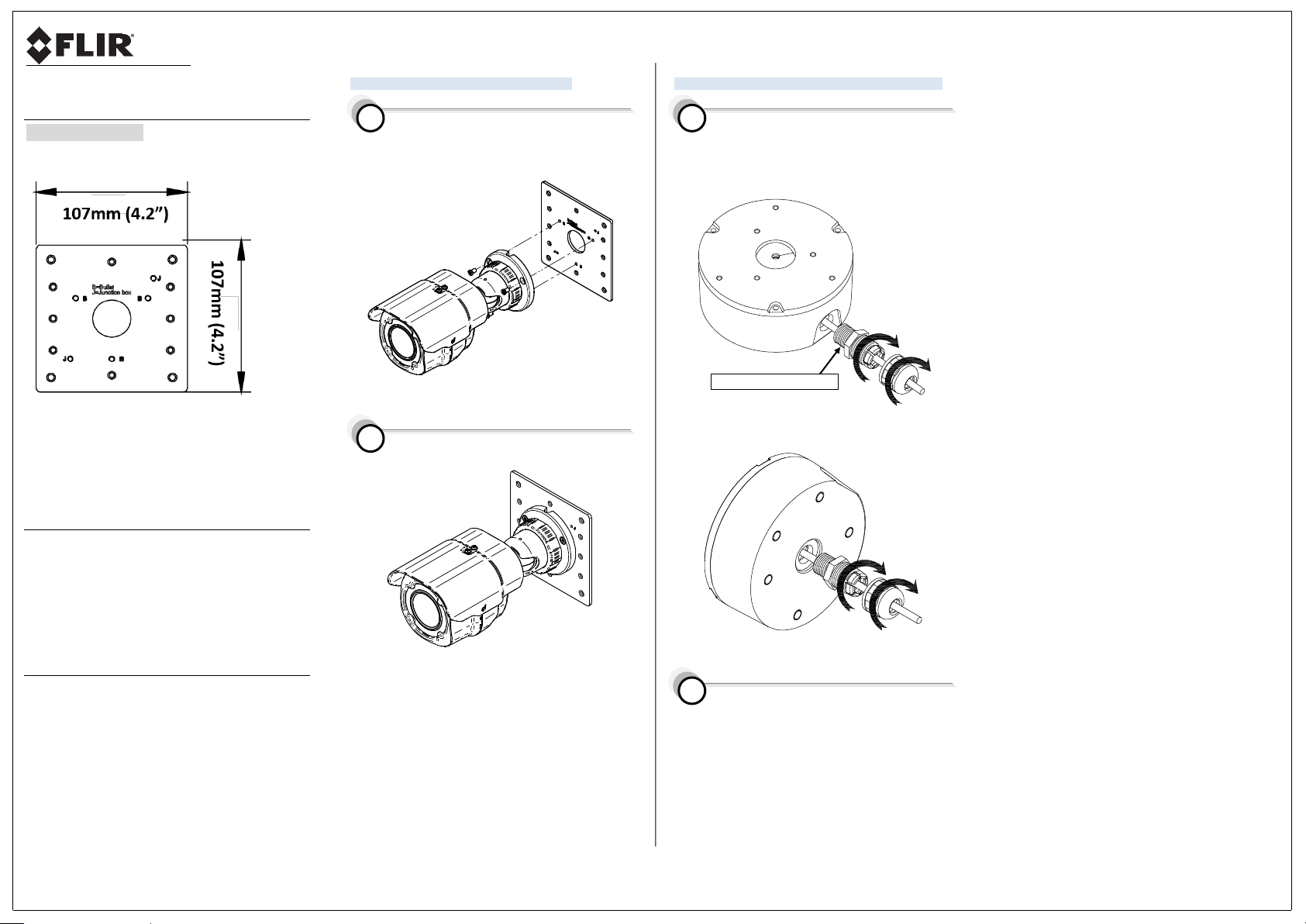
1. Product Overview
FIGURE 1-1: ADAPTOR PLATE DIMENSIONS
The Adaptor plate is used to attach the bullet camera to the
mounting surface or to a junction box which is attached to the
mounting surface.
2. Installation and Mounting
Package Contents
Check if everything in the package matches your purchase order
form and packing slip. The package should include the following
items:
1x Adaptor plate
3x M4x8L screws
2x M4x15L screws
1x Printed quick guide
Please contact your dealer if any item is missing.
Required Tools
Use the following tools to complete the installation:
A drill
A Phillips head screwdriver
A T20 torx wrench
Wire cutters
Connecting the Camera to the Adaptor Plate
Prior to assembly, mount the adaptor plate onto the site
surface, using Single Gang, Dual Gang, or 4S mounting. Use
a Phillips screwdriver to tighten the bullet camera body to the
adaptor plate by fastening the three supplied M4x8L screws.
FIGURE 2-1: FASTEN CAMERA TO ADAPTOR PLATE
The bullet camera is mounted onto the site surface with the
adaptor plate assembled as illustrated below:
FIGURE 2-2: COMPLETED ASSEMBLY
Connecting Camera, Adaptor Plate, and Junction Box
If your site installation requires you to attach the camera to
a junction box, select either side conduit installation or
bottom conduit installation (see figures below). Feed the
cable through the waterproof compression gland. Then
tightly screw the compression gland clockwise onto the
side or bottom conduit hole of the junction box.
FIGURE 2-3: SIDE CONDUIT JUNCTION BOX INSTALLATION
FIGURE 2-4: BOTTOM CONDUIT JUNCTION BOX INSTALLATION
Prior to assembly, mount the adaptor plate using either
Single Gang, Dual Gang, or 4S mounting technique.
1 1 2
2
Page 2
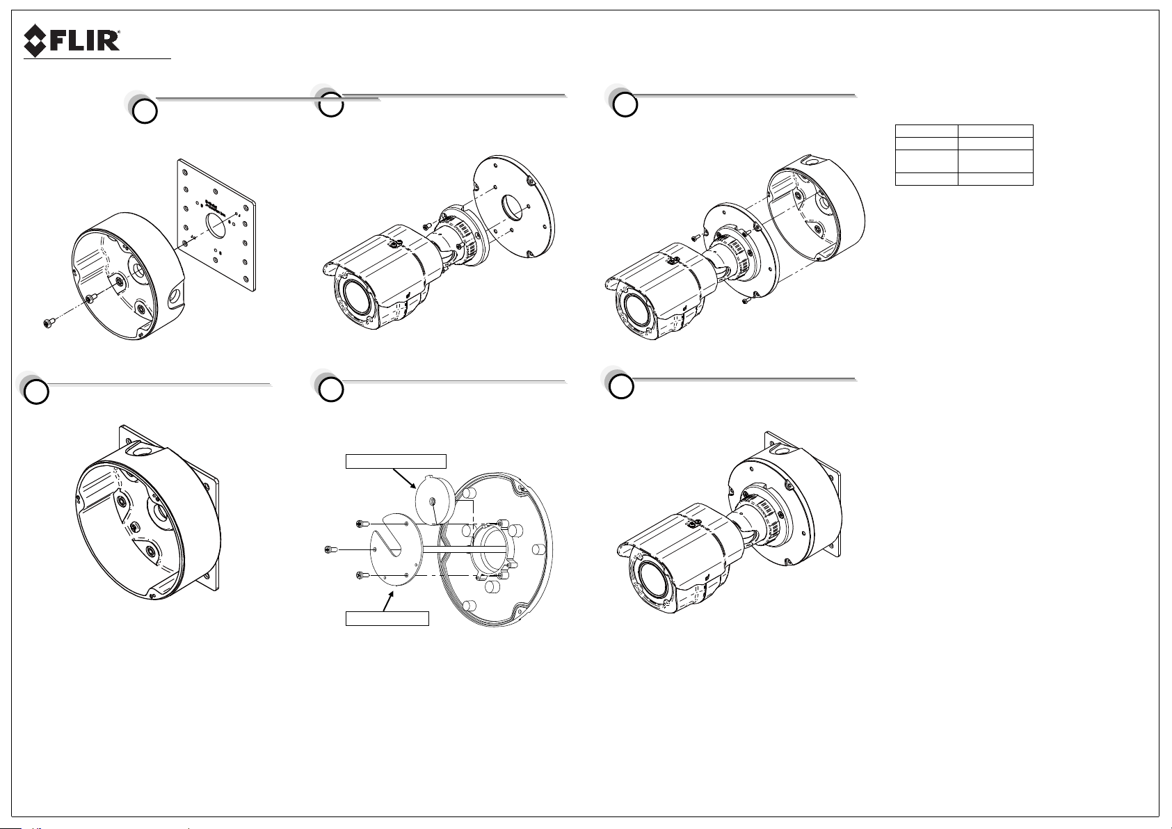
Waterproof Rubber Sealing
Holding Bracket Plate
Using a Phillips screwdriver, fasten the
junction box to the adaptor plate by screwing the two
supplied M4x15L screws according to the required cable
wiring.
FIGURE 2-5: ATTACH JUNCTION BOX TO ADAPTOR PLATE
The junction box is attached to the adaptor plate as shown
below:
FIGURE 2-6: ASSEMBLED JUNCTION BOX AND ADAPTOR PLATE
Feed the camera cables through the upper plate of the
junction box. Then attach the camera to the upper plate by
screwing the three supplied M4x8L screws clockwise.
FIGURE 2-4: ATTACH CAMERA TO UPPER PLATE
Feed the cables through the waterproof rubber sealing on
the rear of the upper plate. Then insert the cables through
the holding bracket plate and screw the three supplied
screws.
FIGURE 2-5: PREPARING THE CABLES
Feed the cables through the junction box. Then connect
them to the cable exiting from the bottom or side conduit
hole. Attach the junction box to the upper plate and bullet
camera by fastening the three M3x0.5P 8mm SUS screws.
FIGURE 2-6: ATTACH JUNCTION BOX TO UPPER PLATE
The adaptor plate, junction box, and bullet camera are
assembled and attached to the site surface according to
the site requirements (bottom conduit installation shown
below).
FIGURE 2-7: ASSEMBLED CAMERA, ADAPTOR PLATE, AND JUNCTION BOX
3. Specifications
Material
Aluminum
Color
White
Dimensions
107 x 107 x 3mm
(4.2 x 4.2 x 0.1”)
Weight
82g (2.9 oz.)
4
8
7
5 6 3
 Loading...