

IMPORTANT:
This camera includes an Auto Mechanical IR Cut Filter. When the
camera changes between Day/Night viewing modes, an audible clicking
noise may be heard from the camera. This clicking is normal, and
indicates that the camera filter is working.
See the full OSD menu tree below:
On-Screen Display (OSD) Menu
To use the OSD menu:
1. In Live View, click the channel that has the camera connected to open in
full-screen.
2. Right-click and click Pan/Tilt/Zoom. Enter the system user name and
password if prompted. The PTZ menu opens.
3. Click the arrow in the PTZ control window to show advanced controls.
4. Click . The OSD menu appears over the camera image.
5. Use the on-screen controls to configure menu items:
• Up / down arrows: Select menu items.
• Left / right arrows: Change values for menu items.
• Esc: Exit the OSD menu.
• Enter: Confirm selection.
Select Return to return to the previous menu, or Exit from the main menu
to exit.
NOTE: These instructions are based on current MPX DVR interface. If you
are not able to access your DVR’s OSD menu by following these steps,
please use the instructions in your DVR manual instead.
You can configure the camera’s advanced settings on an MPX DVR using
the OSD menu.
Format
Video Mode
Backlight Mode
Image Adjustment
Image Mode
Sharpness
Brightness
Contrast
Saturation
Sharp Suppress
Gamma
2 DNR
3 DNR
Exposure
Exposure Mode
Exposure Level
Exposure Speed
Anti-flicker
White Balance
Day/Night
Language
Advanced
Camera Title
Mirror
Horizontal Mirror
Vertical Mirror
D-Zoom
Lens Type
Audio Mode
Smart IR
Privacy Mask
RS485 Setup (service only)
Address
System Information
Factory default
Exit
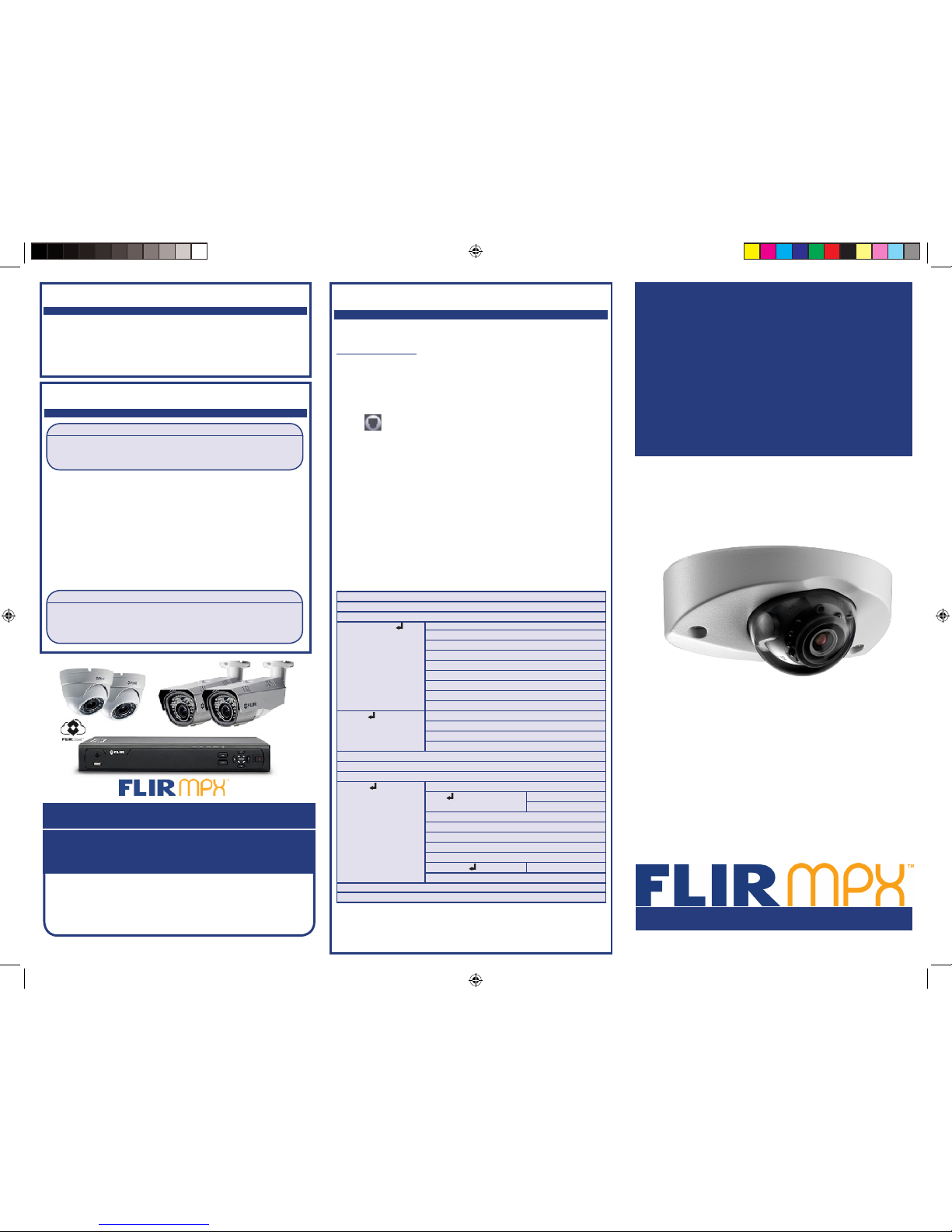
Package Contents
C243MT2 Series
Quick Start Guide
English Version 2.0
www.flir.com/security/pro
Safety Precautions
• Use an appropriate low-voltage power cable to prevent fire or
electrical shock.
• Make sure to install the camera in an area that can support the
camera weight.
• There are no user serviceable parts inside the camera. Please do not
disassemble the camera.
• Do not clean the lens cover with an abrasive cleaning material.
Please use a soft cloth to clean the lens cover.
• Do not point the cameras directly towards the sun or a source of
intense light.
2.1MP Discreet Vandalproof
MPX Audio Dome Camera
• 2.1MP Discreet Vandalproof MPX Audio Dome Camera
• Mounting Kit
• Mounting Template
• Allen Key
• Power Pigtail
C243MT2_QSG_EN_R1
ATTENTION:
A REGULATED (UL / CSA APPROVED) power supply is REQUIRED
for use with this camera. Use of a non-regulated, non-conforming
power supply can damage this product and voids the warranty.
FLIR Systems, Inc., Copyright © 2016
As our products are subject to continuous improvement, FLIR
Systems Inc. reserves the right to modify product design,
specifications and prices, without notice and without incurring
any obligation. E&OE
flir.com/security/pro
VISIT
IT’S ALL ON THE WEB!
MPX
Connect to the included
power pigtail or a 12V
DC power adapter
(not included).*
Powering the Camera
Camera Wiring
1. Connect the BNC connector on the camera to the video cable. See
“Camera Wiring” for details.
2. DC Power—Power Pigtail: Connect the included power pigtail to the
camera. Connect the terminating wires of the cable directly to the DC
power source.
OR
3. DC Power—Power Adapter: Connect a 12V DC power adapter (not
included) to the camera and a local power outlet.
NOTE: For pigtail connection with 12V DC, make sure to check polarity
specifications on the power adapter.
* Camera focus may be affected if the power connection is too
long. It is recommended not to extend the power connection
past 200ft (61m).
** Supports audio transmission.
Connect to an MPX
DVR**
Disabling Camera Audio
ATTENTION:
Test the camera prior to selecting a permanent mounting location by
temporarily connecting the camera(s) and cables to the DVR.
Installing the Camera
Extension Cable Options
Specification Maximum Length
RG59 20AWG Conductor 95% Braid
CSA/UL or C(UL) Approved
Up to 1000ft (300m)
†
RG6 20AWG Conductor 95% Braid CSA/
UL or C(UL) Approved
Up to 2000ft (600m)
†
Analog CCTV Balun Up to 300ft (91m)
† Long cable runs over 1000ft (300m) may be affected by electromechanical interference (EMI), which can increase the amount of noise in
the picture in some installations.
The entire length of the cable run must be made using a single extension
cable between the camera and the DVR.
C243MT2_QSG_EN_R1
Before installing the camera:
Decide whether to run the cables
through the wall / ceiling (drilling
required) or along the wall / ceiling.
NOTE: If you run the cable along the wall / ceiling, it needs to go
through cable notches in the camera base and cover. This will keep
the camera base flush to the surface when mounted. Use pliers to
break off the perforated metal tab on the camera cover, and then
align the cable notch in the camera cover with the cable notch in the
camera base.
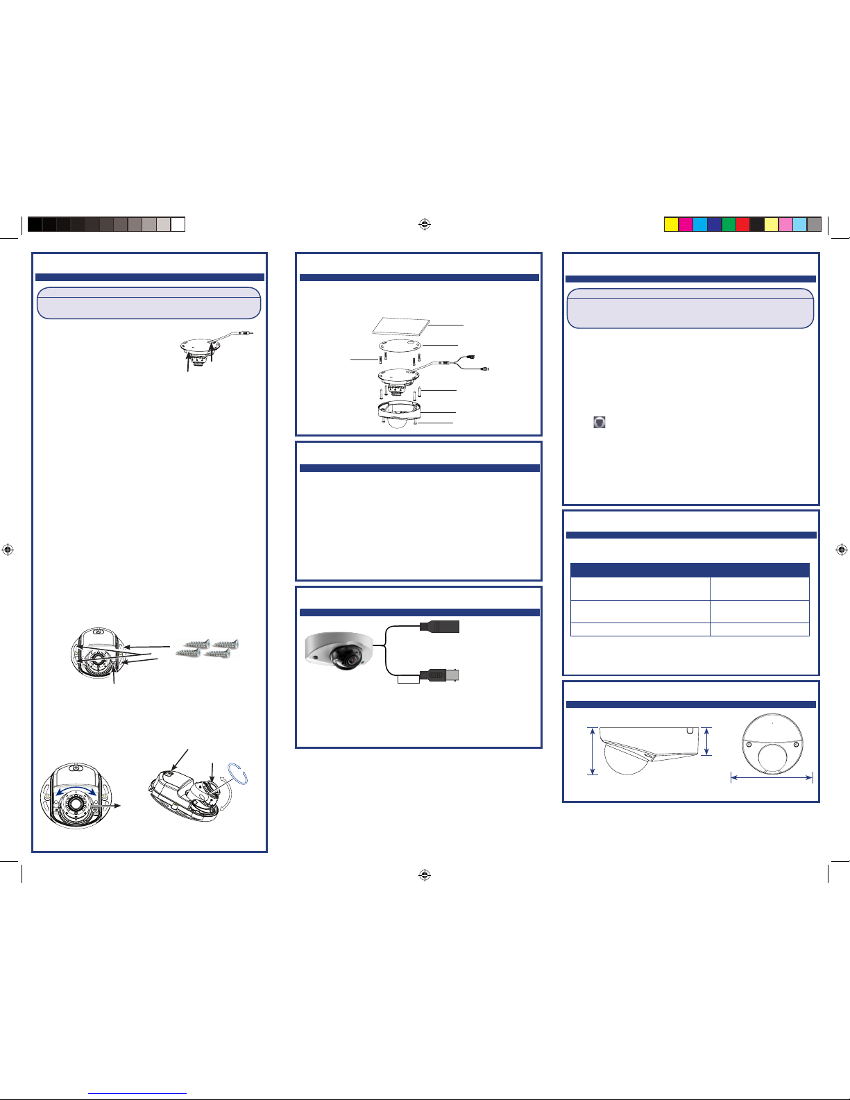
To install the camera:
1. To separate the camera cover from the camera base, loosen the
screws located on either side of the camera cover using the
included Allen key.
2. Use the included mounting template to mark holes for the
mounting screws.
3. Drill the holes and then feed the cable through the mounting
surface or cable notch.
NOTE: Insert the included drywall anchors if installing the camera
in drywall.
4. Connect cables as shown in the section “Connecting the
Camera”.
5. Mount the camera base to the surface using the provided
mounting screws. Make sure all screws are fastened tightly.
01
01
01
Cable Notch
6. Use a Philips head screwdriver (not included) to loosen the lens
module adjustment screw. Do not loosen all the way.
7. Adjust the angle of the camera as needed.
8. Tighten the adjustment screw when finished.
A) Turn the lens holder up to 45°.
B) Tilt the lens module up to 90°.
C) Rotate the lens module 360°.
Camera Base
Lens Holder
Lens Module
A
B
C
01
01
01
Mounting Surface
Mounting Template
Drywall Anchors
Mounting Screws
Camera Cover
Camera Mount Screw
Adjustment Screw
Installing the Camera (continued)
9. Cover the camera base with the camera cover.
10. Tighten the screws on either side of the camera cover.
WARNING:
Audio recording without consent is illegal in certain jurisdictions. FLIR
Systems assumes no liability for use of its products that does not conform
with local laws.
Audio is enabled by default. To disable camera audio through a MPX recorder:
1. In Live View, double-click the camera channel to open in full-screen.
2. Right-click and then click PAN/TILT/ZOOM. Enter the system user name
and password if prompted. The PTZ menu opens.
NOTE: If prompted, set the control mode and protocol for the channel
that the camera is connected to in the PAN/TILT/ZOOM setting page.
3. Click the arrow in the PTZ control window to show advanced controls.
4. Click . In Menu Operation, click Enter. The OSD menu appears over
the camera image.
5. Select the Advanced menu using the on-screen controls.
6. Select the Audio Mode option and choose OFF.
7. Click Enter.
NOTE: These instructions are based on current MPX DVR interface. If
you are not able to access your DVR’s OSD menu by following these
steps, please use the instructions in your DVR manual instead.
Camera Dimensions
1.5”
37mm
2.0”
50mm
4.2”
105mm
Microphone
 Loading...