

Page 1
Language
Video Format
Backlight
OFF
WDR
BLC
HLC
DNR
Advanced Lens ELC
ALC
Exposure
Brightness
Shutter
Sens-Up
AGC
White Balance
Auto
ATW
Preset
Manual
Day&Night
Mode
Delay
D N Level
N D Level
Smart IR
Smart IR Level
Image
Sharpness
Color Gain
Freeze
Flip
D-Zoom
Defog
Special Black Level
Privacy
DP Comp
Reset
Version
Exit
Package Contents
MODEL: C237BC/
C237BCP
QUICK START GUIDE
English Version 2.0
www.flirsecurity.com/pro
FLIR Systems, Inc., Copyright © 2015
As our products are subject to continuous improvement, FLIR
Systems Inc. reserves the right to modify product design,
specifications and prices, without notice and without incurring
any obligation. E&OE
Safety Precautions
• Use an appropriate low voltage power cable to
prevent fire or electrical shock.
• Make sure to install the camera in an area that can
support the camera weight.
• There are no user serviceable parts inside the
camera. Please do not disassemble the camera.
• Do not clean the lens cover with an abrasive cleaning
material. Please use a soft cloth to clean the lens
cover.
1.3MP Motorized Varifocal Lens
Bullet Camera
www.flirsecurity.com/pro
VISIT
• 1x 1.3MP Motorized Varifocal Lens WDR Bullet
Camera
• 3x Mounting Screws
• 3x Drywall Anchors
• 1x Allen Key
• 1x Mounting Template
NOTE: 12V DC / 24V AC power supply not included.
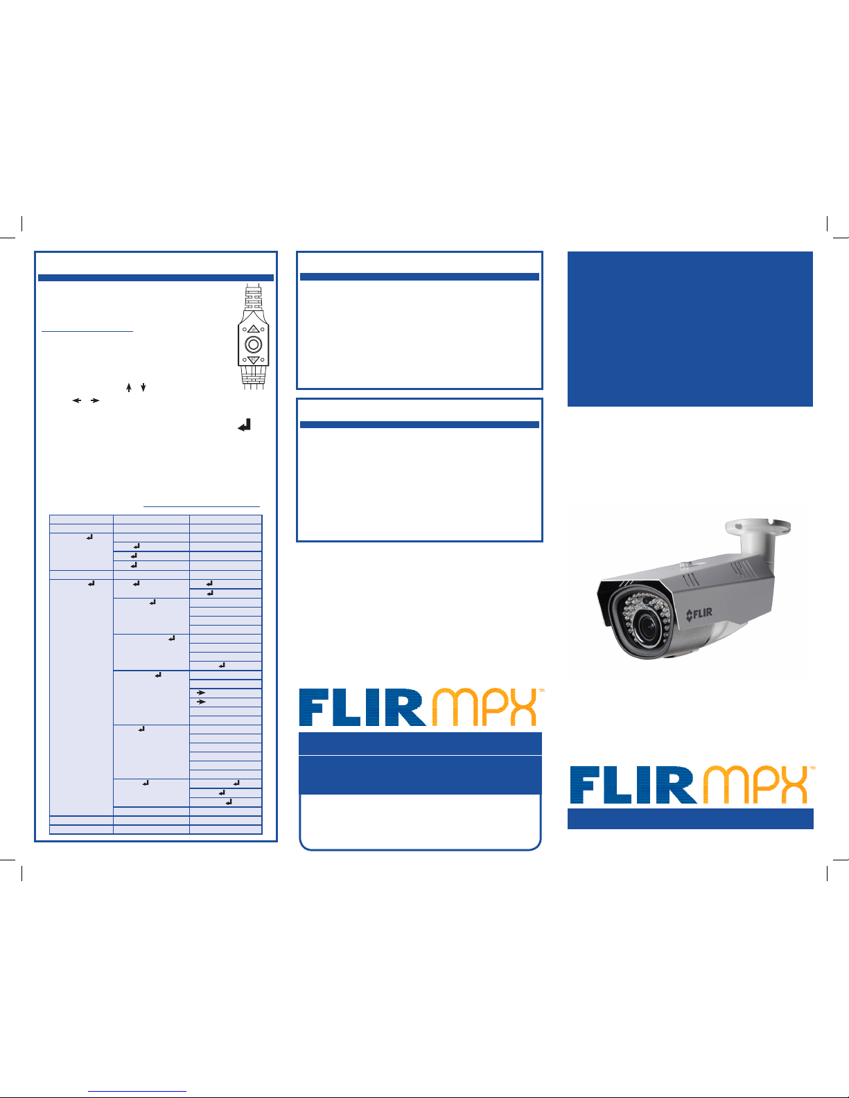
On-Screen Display (OSD) Menu
To use the OSD menu:
• OPTIONAL: Connect a test monitor to the
camera’s analog (yellow) BNC connector.
• Push the middle of the joystick to open the
OSD menu.
• Move the joystick / to select a setting,
then / to change the setting value.
• Push the middle of the joystick to confirm selection.
• Arrows beside settings indicate a submenu ( ).
Select the setting and push the joystick to enter.
• Select RETURN and push the joystick to return to the
previous menu, or EXIT from the main menu to exit.
Configure OSD menu options using the
integrated control stick on the camera
cable (see image to the right).
See the full OSD menu tree below. For detailed
explanation of camera settings, see the OSD
instruction manual on www.flirsecurity.com/pro.
IT’S ALL ON THE WEB!
Page 2
Analog
MPX
Connect to a
12V DC or 24V AC
power supply.*
Image Sensor
1/3” 1.3MP CMOS
Video Format
NTSC (C237BC)/PAL (C237BCP)
Effective Pixels
H: 1305 V: 1049
Resolution
Digital: 720p
Analog: 960H
Scan System
Progressive
Sync System
Internal
S / N Ratio
≥ 50dB (AGC Off)
Iris
AES
AES Shutter Speed
1/60 (1/50) ~ 1/60,000 sec.
Min. Illumination
0.1 LUX (IR Off)
0 LUX (IR LEDs On)
Video Output
Digital: 720p MPX HD-CVI
Analog: Composite 1.0Vpp @ 75ohm
Lens Focal Length / Type
2.8-12mm F1.4 / Varifocal
FOV (Horizontal)
Digital: 30-80°
Analog: 30-80°
Termination
BNC Type
IR Range / Qty.
115ft / 35m; 42 IR LED’s
Power Requirement
12V DC ± 10%
24V AC ± 10%
Power Consumption
12V DC: 750mA MAX with IR LED
24V AC: 470mA MAX with IR LED
Operating Temp. Range
–22° ~ 140°F / –30° ~ 60°C
Environmental Rating
IP66
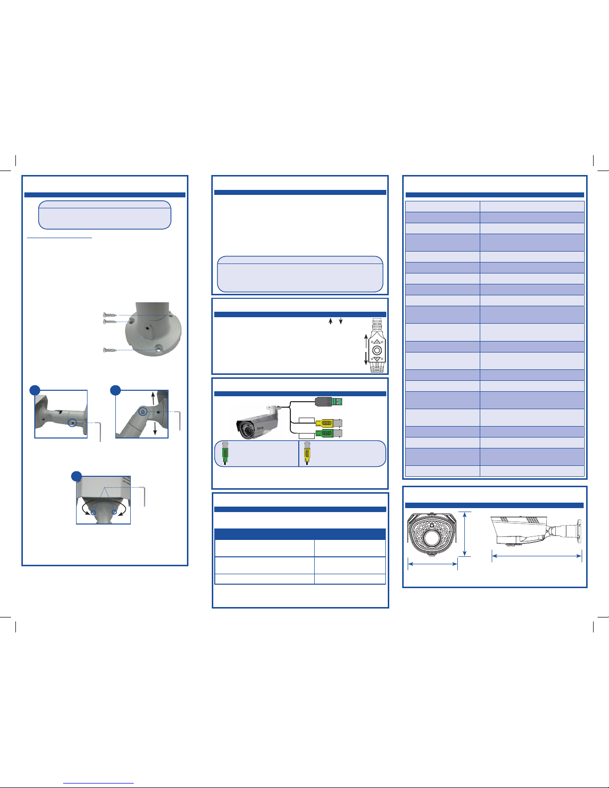
Dimensions (W x H x D)
3.9” x 3.5” x 10.6”
99mm x 89mm x 269mm
Weight (including stand)
1.7lbs / 0.8kg
Camera Dimensions
Camera Specifications
To install the camera:
1. Use the included mounting template to mark and drill
holes for the included mounting screws.
NOTE: Insert the included drywall anchors if installing into
drywall.
2. Connect the video and power cable as detailed in the
section ‘Setting up the Camera’.
3. Attach the camera
base to the mouting
surface using the
included screws.
4. Set the position and angle of the camera using the
provided Allen key.
5. Remove the protective film from the camera lens.
Setting up the Camera
10.6”
269mm
3.9”
99mm
3.5”
89mm
ATTENTION:
Test the camera prior to selecting a permanent
mounting location by temporarily connecting the
camera(s) and cables to the DVR.
Installing the Camera
WARNING:
A REGULATED 12V DC or 24V AC power supply is REQUIRED for
use with this camera. Use of a non-regulated, non-conforming
power supply can damage this product and voids the warranty.
Camera Wiring
1. Connect one of the two BNC connectors on the camera to the
video cable. See “Camera Wiring” for details.
2. Connect a power source to the power terminal block. The
camera supports both 12V DC and 24V AC power supplies.
NOTE: Make sure to follow correct polarity as marked on the
power connector. For AC power, connect multiple cameras using
consistent wiring polarity to prevent video rolling.
Extension Cable Options
Specification Maximum Length
RG59 20AWG Conductor 95% Braid
CSA/UL or C(UL) Approved
Up to 1500ft (455m)
†
RG6 20AWG Conductor 95% Braid
CSA/UL or C(UL) Approved
Up to 2300ft (700m)
†
Analog CCTV Balun Up to 300ft (91m)
† Long cable runs over 1000ft (300m) may be affected by
electro-mechanical interference (EMI), which can increase the
amount of noise in the picture in some installations.
The entire length of the cable run must be made using a
single extension cable between the camera and the DVR.
B) Loosen lower screw with
the Allen key to adjust the
camera’s vertical position.
C) Loosen the screws on either side of the
camera stand with the Allen key to rotate the
camera housing. Loosen the right-side to make
fine adjustments, or the left-side for broad
adjustments.
A) Loosen the screw on the
camera base with the Allen
key to tighten / loosen the
stand connection. Adjust the
camera’s horizontal position.
A B
C
MPX
Connect to an MPX DVR for
720p viewing / recording.
Analog
Connect to an analog DVR for
960H viewing / recording.
Adjusting Zoom & Focus
Hold the joystick on the camera cable / to zoom
in / out. The camera will focus itself automatically.
NOTE: You can also adjust zoom and focus
remotely if the camera is connected to a FLIR
MPX DVR using the MPX video connector. See
your MPX DVR’s instruction manual for details.
* Camera focus may be affected if the power connection is too
long. It is recommended not to extend the power connection
past 200ft (61m).
 Loading...