

Page 1

INSTALLATIONGUIDE
FLIR
BLACKFLY®S
Copyright © 2015-2017 FLIR Integrated Imaging Solutions Inc.
Allrights reserved.
Version 4.0
Revised 5/4/2017
Page 2

FCC Compliance
This device complies with Part 15 of the FCC rules. Operation is subject to the following two conditions: (1) This
device may not cause harmful interference, and (2) this device must accept any interference received, including
interference that may cause undesirable operation.
Korean EMCCertification
The KCC symbol indicates that this product complies with Korea’s Electrical Communication Basic Law regarding
EMC testing for electromagnetic interference (EMI) and susceptibility (EMS).
Hardware Warranty
The warranty for the BlackflyS camera is 3 years. For detailed information on how to repair or replace your
camera, please see the terms and conditions on our website.
Export Control
The ECCN for this product is EAR099.
WEEE
The symbol indicates that this product may not be treated as household waste. Please ensure this
product is properly disposed as inappropriate waste handling of this product may cause potential
hazards to the environment and human health. For more detailed information about recycling of this
product, please contact us.
Trademarks
Names and marks appearing on the products herein are either registered trademarks or trademarks of FLIR
Systems, Inc. and/or its subsidiaries.
Licensing
To view the licenses of open source packages used in this product please see What open source packages does
firmware use?
Copyright © 2015-2017 FLIR Integrated Imaging Solutions Inc.
Allrights reserved.
Page 3

Table of Contents
1 Blackfly S Installation Guide 1
2 Handling Precautions and Camera Care 2
3 BlackflyS Installation 3
3.1 Preparing for Installation 3
3.2 Installing Your Interface Card and Software 4
3.3 Installing Your BlackflyS 6
3.4 Powering Your BlackflyS 7
4 Tools to Control the BlackflyS 8
4.1 Using the Spinnaker® Software Development Kit 8
4.1.1 SpinView Camera Evaluation Application 8
4.1.2 Custom Applications Built with the Spinnaker API 8
4.2 Using GenICam Applications 9
5 Configuring BlackflyS Setup 11
5.1 Configuring Camera Drivers 11
5.2 Configuring the IP Address—GigEonly 11
5.3 Allocating Bandwidth—GigEonly 12
5.3.1 Determining Bandwidth Requirements 12
5.4 Configuring Other Ethernet Settings—GigEonly 13
5.4.1 Stream Channel Destination Address 13
5.4.2 Heartbeat 13
5.5 Camera Firmware 15
5.5.1 Determining Firmware Version 15
5.5.2 Upgrading Camera Firmware 15
6 BlackflyS Physical Interface 16
6.1 BlackflyS Physical Description 16
6.2 BlackflyS Dimensions 17
6.3 Interface Connector 19
6.3.1 Ethernet Connector 19
6.3.2 USB3.1 Connector 19
6.4 Interface Cables 20
6.5 Interface Card 20
6.6 General Purpose Input/Output (GPIO) 21
5/4/2017
©2015-2017 FLIR
Integrated Imaging
Solutions Inc.
Allrights reserved.
FLIRBlackfly®S Installation Guide i
Page 4

6.7 Mounting with the Case or Mounting Bracket 23
6.8 Case Temperature and Heat Dissipation 24
6.9 Lens Mounting 25
6.9.1 Back Flange Distance 25
6.10 Non-Volatile Flash Memory 26
6.11 Dust Protection 26
6.12 Infrared Cut-Off Filters 27
7 Input/Output Control 28
7.1 General Purpose Input/Output (GPIO) 28
7.2 GPIO Electrical Characteristics 30
8 Troubleshooting 32
8.1 Support 32
8.2 Status Indicator LED 33
Contacting Us 34
Revision History 34
5/4/2017
©2015-2017 FLIR
Integrated Imaging
Solutions Inc.
Allrights reserved.
FLIRBlackfly®S Installation Guide ii
Page 5

1 Blackfly S Installation Guide
Welcome to the BlackflyS camera. We offer a number of resources to assist you with the BlackflyS.
n Release Notes—information about the current firmware release including feature additions or changes,
bug fixes, and known issues.
n Specifications—information about the camera model as it performs with the current firmware.
n Getting Started—quick start guide for installing the camera and software.
n Installation Guide—information about installing the camera and SDK, the physical interface and
mechanical properties, troubleshooting and how to get help. This document is available as a PDF for
download or as a webpage included in the firmware release package.
n Technical Reference—information about the features supported by the camera model with the current
firmware, including: image format control, acquisition control, sequencing, binning/decimation, and others.
This document is available as a PDF for download or as a webpage included in the firmware release
package.
1 Blackfly S Installation Guide
n Firmware—programming inserted into the programmable ROM of the camera that can be updated in-field.
New firmware packages are available for download and include both the firmware file and documentation.
n Spinnaker SDK—software development kit that provides GenICam-compliant controls to create
applications for the camera. Spinnaker is available for download. Each installation includes API
documentation for C, C++, and C#.
Our website provides additional information in our Knowledge Base and Technical Application Note library. As
well, the Downloads site is the portal to access documentation and firmware updates.
5/4/2017
©2015-2017 FLIR
Integrated Imaging
Solutions Inc.
Allrights reserved.
FLIRBlackfly®S Installation Guide 1
Page 6

2 Handling Precautions and Camera Care
2 Handling Precautions and Camera Care
Warning! Do not open the camera housing. Doing so voids the
Hardware Warranty described in the Terms and Conditions on
our website.
Your FLIR digital camera is a precisely manufactured device and should be handled with care. Here are some tips
on how to care for the device.
n Avoid electrostatic charging.
n When handling the camera unit, avoid touching the lenses. Fingerprints will affect the quality of the image
produced by the device.
n To clean the lenses, use a standard camera lens cleaning kit or a clean dry cotton cloth. Do not apply
excessive force.
n Extended exposure to bright sunlight, rain, dusty environments, etc. may cause problems with the
electronics and the optics of the system.
n Avoid excessive shaking, dropping or any kind of mishandling of the device.
Related Knowledge Base Articles
Title Article
Cleaning the imaging surface of your
camera
Knowledge Base Article
10243
5/4/2017
©2015-2017 FLIR
Integrated Imaging
Solutions Inc.
Allrights reserved.
FLIRBlackfly®S Installation Guide 2
Page 7

3 BlackflyS Installation
3.1 Preparing for Installation
What system configuration is recommended?
3 BlackflyS Installation
Recommended
System
Configuration
Operating
System
Windows7,
Windows8, or
Windows10
(32- or 64-bit)
CPU RAM Ports
Intel i5 4 GB
Intel USB3
host controller
Software to run and
compile example code
Microsoft Visual Studio 2010,
Visual Studio 2013, or
Visual Studio 2015
Note: Refer to Technical Application Note 10359 for important
information on recommended USB 3.0 system components.
Do you have all the parts you need?
To install your camera you will need the following components:
n For GigEcameras—Ethernet cable (see Interface Cables) and Powered Ethernet switch or Ethernet power
injector (if using PoE)
n For USB3 cameras—USB 3.0 cable (see Interface Cables)
n 6-pin GPIOcable (see General Purpose Input/Output (GPIO))
n C-mount Lens (see Lens Mounting )
n Tripod adapter (optional) (see Mounting with the Case or Mounting Bracket)
n Interface card (see Interface Card)
FLIR sells a number of the additional parts required for installation. To purchase, visit the Accessories page.
Do you have a downloads account?
The downloads page has many resources to help you operate your camera effectively, including:
n Spinnaker
n Firmware updates and release notes
n Dimensional drawings and CADmodels
n Documentation
To access the software and firmware downloads you must have a downloads account.
5/4/2017
©2015-2017 FLIR
Integrated Imaging
Solutions Inc.
Allrights reserved.
®
SDKsoftware, including drivers (required for installation)
FLIRBlackfly®S Installation Guide 3
Page 8

1. Go to our website: www.ptgrey.com.
2. In the upper right corner, click Register.
3. Complete the form, then click Register.
After you submit your registration, you will receive an email with instructions on how to activate your account.
3.2 Installing Your Interface Card and Software
1. Install your Interface Card
Ensure the card is installed per the manufacturer's instructions.
Connect the internal IDE or SATApower connector on the card to the computer power
supply.
Alternatively, use your PC's built-in host controller, if equipped.
3 BlackflyS Installation
Open the Windows Device Manager. Ensure the card is properly installed. Ethernet cards appear under Network
Adapters. USB3 cards appear under Universal Serial Bus Controllers. An exclamation point (!) next to the
card indicates the driver has not yet been installed.
2. Install the Spinnaker® Software
Note: For existing users who already have Spinnaker installed,
we recommend ensuring you have the latest version for optimal
performance of your camera. If you do not need to install
Spinnaker, use SpinView to install and enable drivers for your
card.
a. Login to the Downloads page.
b. Select your Product Family, Camera Model and Operating System from the drop-down lists.
c. Click on the Software search results to expand the list.
d. Click the appropriate link to begin the download and installation.
After the download is complete, the Spinnaker setup wizard begins. If the wizard does not start automatically,
double-click the .exe file to open it. Follow the steps in each setup dialog.
3. For Ethernet cards: Enable jumbo frames
a. In Start->All Programs-> Point Grey Spinnaker SDK->SpinView, right click on the Network Adapter
and select Adapter Configuration, then select IP Configuration.
b. Click Open Network Connections.
5/4/2017
©2015-2017 FLIR
Integrated Imaging
Solutions Inc.
Allrights reserved.
FLIRBlackfly®S Installation Guide 4
Page 9

c. Click Change Settings.
d. Click on the Advanced tab and from the Settings list select Jumbo Packet.
e. Set the Value to 9014 Bytes and click OK.
3 BlackflyS Installation
5/4/2017
©2015-2017 FLIR
Integrated Imaging
Solutions Inc.
Allrights reserved.
FLIRBlackfly®S Installation Guide 5
Page 10
3.3 Installing Your BlackflyS
1. Install the Tripod Mounting Bracket (optional)
The ASA and ISO-compliant tripod mounting bracket attaches to the camera using the
included screws.
2. Attach a Lens
Unscrew the dust cap from the lens holder to install a lens.
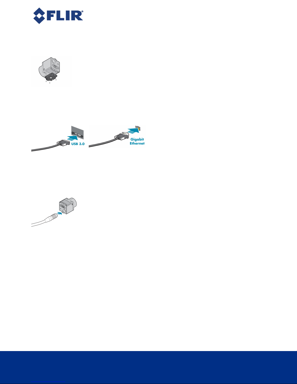
3. Connect the interface Card and Cable to the Camera
3 BlackflyS Installation
Plug the interface cable into the host controller card and
the camera. The cable jack screws can be used for a
secure connection.
When the camera is first connected, the operating system automatically installs the camera driver. Camera
drivers are available with the Spinnaker SDK installation.
a. If using PoE, connect a powered Ethernet switch or Ethernet power injector in between the card and the
camera.
4. Plug in the GPIO connector if required
GPIOcan be used for power, trigger, and strobe.
5. Confirm Successful Installation
Run the SpinView application: Start->All Programs-> Point Grey Spinnaker->SpinView
The SpinView application can be used to test the camera's image acquisition capabilities.
Changes to your camera's installation configuration can be made using the SpinView application.
5/4/2017
©2015-2017 FLIR
Integrated Imaging
Solutions Inc.
Allrights reserved.
FLIRBlackfly®S Installation Guide 6
Page 11

3.4 Powering Your BlackflyS
For GigE cameras—Power can be provided over the Ethernet interface (PoE). To use PoE, you must also have a
powered Ethernet card, a powered Ethernet switch, or an Ethernet power injector.
For USB3 cameras—The USB 3.0 Micro-B connector provides a power connection between the camera and the
host computer. The ideal input voltage is nominal 5 V DC. For the USB 3.0 connector to provide power, the host
controller must be connected to the computer's power supply.
Power can also be provided externally through the GPIO interface: 12 V nominal (8 - 24 V). Power consumption is
3W maximum.
If both power sources are connected the camera always uses external power over the GPIO connector.
Note: Some systems, especially those with laptop computers or
longer cable lengths, may not provide adequate power through
the USB 3.0 cable which could result in intermittent operation.
The use of external power through the GPIOis required for
these systems.
3 BlackflyS Installation
Related Knowledge Base Articles
Title Article
How can I power my USB 3.0 camera?
The camera does not transmit images for the first 100 ms after power-up. The auto-exposure and auto-white
balance algorithms do not run while the camera is powered down. It may therefore take several images to get a
satisfactory image.
When the camera is power cycled (power disengaged then re-engaged), the camera reverts to its default factory
settings, or if applicable, a saved user set.
Knowledge Base Article 10240
5/4/2017
©2015-2017 FLIR
Integrated Imaging
Solutions Inc.
Allrights reserved.
FLIRBlackfly®S Installation Guide 7
Page 12

4 Tools to Control the BlackflyS
4 Tools to Control the BlackflyS
The BlackflyS's features can be accessed using various controls, including:
n Spinnaker SDK including API examples
n SpinView camera evaluation application, included in the Spinnaker SDK installation
n Third-party GenICam applications
4.1 Using the Spinnaker®Software Development Kit
You can monitor or control features of the camera through Spinnaker API examples provided in the Spinnaker SDK,
or through the SpinView camera evaluation application. A Programmer's Guide and API Reference is included in
the installation.
4.1.1 SpinView Camera Evaluation Application
The SpinView application is a generic, easy-to-use streaming image viewer included with the Spinnaker SDK that
can be used to test many of the capabilities of your camera. It allows you to view a live video stream from the
camera, save individual images, adjust the various attributes, frame rates, features and settings of the camera. It
includes tools for updating firmware, managing drivers, IP addressing, and activity logging.
4.1.2 Custom Applications Built with the Spinnaker API
The Spinnaker SDK includes a full Application Programming Interface that allows you to create custom
applications to control your camera. Included with the SDK are a number of source code examples to help you get
started.
Spinnaker API examples are provided for C, C++, C#, and VB.NET languages. These examples are precompiled
for your convenience.
5/4/2017
©2015-2017 FLIR
Integrated Imaging
Solutions Inc.
Allrights reserved.
FLIRBlackfly®S Installation Guide 8
Page 13

4.2 Using GenICam Applications
GigE Vision is an interface standard that allows for fast image transfer over Ethernet networks. All cameras
supporting GigE Vision interact the same way with software also supporting GigE Vision.
USB3 Vision is a communication interface for vision applications based on the USB 3.0 technology. All cameras
supporting USB3 Vision interact the same way with software also supporting USB3 Vision.
For more information on the standard, visit visiononline.org.
The standard defines required elements for camera identification, control, and output. It uses GenICam, a
programming interface for camera attribute control. GenICam allows camera vendors to define features and
attributes in an XML file stored inside the camera. The file is parsed by the host application when the camera is
initially discovered. One of the key benefits of GenICam is the ability for camera vendors to introduce new
camera-specific features without needing to update the host application.
Each camera attribute, such as exposure time, is controlled by a specific GenICam feature. The camera includes
an XML device description file for interfacing with third-party GenICam-compliant APIs.
For more information on GenICam, visit emva.org.
Getting Started with Third-Party Applications Resources
Title Article
Getting Started with OpenCV
4 Tools to Control the BlackflyS
Technical Application Note
10861
Getting Started with MATLAB
Getting Started with MVTec HALCON
Getting Started with Cognex VisionPro
Getting Started with Adaptive Vision
Getting Started with Matrox Imaging Library
Getting Started with Matrox Design Assistant
Getting Started with NI-MAX and LabVIEW
Getting Started with NI Vision Builder for Automatic Inspection
USB3 Vision and Third-Party Applications Resources
Title Article
Using USB3Vision cameras with National Instruments' Acquisition
Software
Technical Application Note
10898
Technical Application Note
10793
Technical Application Note
10794
Technical Application Note
10865
Technical Application Note
10790
Technical Application Note
10862
Technical Application Note
10791
Technical Application Note
10875
Technical Application Note
10337
5/4/2017
©2015-2017 FLIR
Integrated Imaging
Solutions Inc.
Allrights reserved.
FLIRBlackfly®S Installation Guide 9
Page 14

USB3 Vision and Third-Party Applications Resources
Title Article
Using USB3Vision cameras with A&BSoftware's ActiveUSB
4 Tools to Control the BlackflyS
Technical Application Note
10335
Using USB3 Vision cameras with Matrox Imaging Library
Using USB3 Vision cameras with MVTec's Halcon software
Using USB3/USB2 cameras with Cognex VisionPro
Technical Application Note
10701
Technical Application Note
10774
Technical Application Note
10788
5/4/2017
©2015-2017 FLIR
Integrated Imaging
Solutions Inc.
Allrights reserved.
FLIRBlackfly®S Installation Guide 10
Page 15

5 Configuring BlackflyS Setup
After successful installation of your camera and interface card, you can make changes to the setup. Use the tools
described below to change the IP Address or the driver for your interface card.
For information on updating your camera's firmware post installation, see Camera Firmware.
5.1 Configuring Camera Drivers
Camera drivers are provided as part of the Spinnaker SDK. The first time the camera is connected to the computer,
the operating system installs the driver.
To manage and update drivers use the SpinView application:
1. Start SpinView:
Start Menu-->All Programs-->Point Grey Spinnaker SDK-->SpinView
2. From the Devices list, select the camera and click the Switch Driver button.
5 Configuring BlackflyS Setup
3. Select the driver from the drop-down list.
4. Click Install Driver.
5.2 Configuring the IP Address—GigEonly
When a new GigE camera is first powered and initialized, a dynamic IP address is assigned to the camera
according to the DHCP protocol. If DHCP addressing fails, a link-local address is assigned. You can configure the
IP address using the GenICam Features Transport Layer Control.
Alternatively, SpinView is a tool included with the Spinnaker SDK that allows you to set the internet protocol (IP)
configuration for any GigE interface cards or FLIR GigE Vision cameras connected to your system. Using
SpinView, you can:
n Set the IP address for the current connection.
n Program a persistent IP address for the camera.
n Configure the default IP addressing behavior of the camera on startup using a persistent IP, DHCP or LLA.
n Enable Jumbo Frames on the GigE NIC.
Both your camera and host adapter must have an IP address on the same subnet. This can be assigned in three
ways:
n Persistent—The camera has a fixed IP address that does not change. Generally the address is within a
closed network range of 192.168.X.X.
5/4/2017
©2015-2017 FLIR
Integrated Imaging
Solutions Inc.
Allrights reserved.
FLIRBlackfly®S Installation Guide 11
Page 16

n Dynamic (DHCP)—The camera is set to automatically obtain an IP address. This means that the IP
address may change (within a range) every time the camera or computer is restarted. It may take up to one
minute for the IP address to resolve and the camera to enumerate.
n Default (LLA)—The camera uses an IP address from the link-local address block 169.254.x.x.
The camera assigns its current IP address in the following sequence:
1. Persistent—Uses the defined IP address. If not available, then;
2. DHCP—Attempts to find a dynamic IP address. If not available, then;
3. LLA—Uses an LLA IP address.
SpinView can automatically force an IP address refresh. This detects the IP address of the Network Interface card
and automatically sets the camera’s IP address relative to the card.
To open SpinView:
Start Menu > All Programs > Point Grey Spinnaker SDK > SpinView
5.3 Allocating Bandwidth—GigEonly
5 Configuring BlackflyS Setup
The User Datagram Protocol (UDP) used by the GigE Vision standard provides no guaranteed transmission or
fixed timing mechanism. Therefore, bandwidth must be managed by the Device Throughput Limit, based on
desired resolution and frame rate.
5.3.1 Determining Bandwidth Requirements
The maximum bandwidth available is 125 MB/s. This includes image data, control data and image resends, which
occur when frames are being dropped. Each image and each packet has a certain amount of overhead that will
use some bandwidth. Therefore, when calculating your bandwidth requirements, you should not attempt to use
the full maximum of 125 MB/s.
To calculate your bandwidth requirements:
Determine your required resolution, frame rate, and pixel format (bytes per pixel)
(Height x Width x Frame Rate x Bytes per Pixel)/1000000 = Bandwidth in MB/s
For example, for an image that is VGA, 82 FPS, Mono8:
640 (H) x 480 (W) x 82 (FPS) x 1 (BPP) = ~25 MB/s
Once you have calculated your required bandwidth, you can allocate an amount to each camera by adjusting the
Device Throughput Limit. Allocating a specific amount to each camera helps to avoid dropped packets due to a
data burst. You would do this in a set up with multiple cameras, or in a situation where the system bandwidth
might be limited or shared due to hardware architecture.
Bandwidth Requirements for Multiple Cameras
Multiple cameras can be set up in two ways: 1) Each camera is connected directly to a single Ethernet port; or, 2)
multiple cameras are connected to a single port through an Ethernet switch.
If using the first method, each camera has the full bandwidth allocation available to it. If using the second method,
the combination of all cameras on a switch cannot exceed the available bandwidth.
5/4/2017
©2015-2017 FLIR
Integrated Imaging
Solutions Inc.
Allrights reserved.
FLIRBlackfly®S Installation Guide 12
Page 17

5 Configuring BlackflyS Setup
Related Knowledge Base Articles
Title Article
Setting Up Multiple
GigECameras
Technical Application Note
10351
5.4 Configuring Other Ethernet Settings—GigEonly
5.4.1 Stream Channel Destination Address
The stream channel destination address (SCDA) register is used to specify the streaming destination IP address.
The default SCDA is the IPaddress of the network or computer to which the camera is connected. It can be set
within a range so that the camera sends data as a multicast. As long as switches in the path between the sender
and receivers support and are configured for multicasting, multiple receivers can listen to the data stream from the
camera.
Multicast addresses are between 224.0.0.0 and 239.255.255.255.
Note: For more information on multicast address assignments,
see http://tools.ietf.org/html/rfc3171
To control SCDA use:
n GenICam—GevSCDA in the Transport Layer Control
5.4.2 Heartbeat
The heartbeat is a mandatory GigE Vision feature to monitor the connection between an application and the
camera. The application must continually reset the heartbeat timer, or the camera assumes an error has occurred
and shuts down the connection.
In general, the Spinnaker API manages the heartbeat at a low level; however the following two features are
controllable: Heartbeat Timeout and Heartbeat Disable.
Heartbeat Timeout
Heartbeat timeout is the time, in milliseconds, that the camera waits before closing the connection. Heartbeat
timeout can be set between 500 ms and 10 seconds. The default setting is 3000 ms (3 seconds). If there is no
communication between the camera and the application for longer than the timeout value, the connection is shut
down.
To control Heartbeat Timeout use:
n GenICam—Under Transport Layer Control, GevHeartbeatTimeout.
n Spinnaker API—The Spinnaker SDK supports configuring heartbeat timeout.
Heartbeat Disable
The heartbeat is enabled by default.
To disable Heartbeat use:
5/4/2017
©2015-2017 FLIR
Integrated Imaging
Solutions Inc.
Allrights reserved.
FLIRBlackfly®S Installation Guide 13
Page 18

n GenICam—Under Transport Layer Control GevGVCPHeartbeatDisable.
n Spinnaker API—The Spinnaker SDK supports disabling heartbeat.
5 Configuring BlackflyS Setup
5/4/2017
©2015-2017 FLIR
Integrated Imaging
Solutions Inc.
Allrights reserved.
FLIRBlackfly®S Installation Guide 14
Page 19

5.5 Camera Firmware
Firmware is programming that is inserted into the programmable read-only memory (programmable ROM) of
most FLIR cameras. Firmware is created and tested like software. When ready, it can be distributed like other
software and installed in the programmable read-only memory by the user.
The latest firmware versions often include significant bug fixes and feature enhancements. To determine the
changes made in a specific firmware version, consult the Release Notes.
Firmware is identified by a version number, a build date, and a description.
5.5.1 Determining Firmware Version
To determine the firmware version number of your camera:
n Query the GenICam Device Control feature DeviceFirmwareVersion.
5.5.2 Upgrading Camera Firmware
Camera firmware can be upgraded or downgraded to later or earlier versions using SpinView, part of the Spinnaker
SDK available from the Downloads page.
5 Configuring BlackflyS Setup
Before upgrading firmware:
n Install the Spinnaker SDK, available from the Downloads page.
n Download the firmware file from the Downloads page.
To upgrade the firmware:
1.
Start Menu-->All Programs-->Point Grey Spinnaker SDK-->SpinView
2. From the Device list, right click the camera and select Update Device Firmware.
If you get a Device is Active warning, close the Display pane or click the Disconnect button and right click
the camera again.
3. Browse to select the firmware file and click Open.
4. Click Yes to continue.
Warning! Do not disconnect the camera during the firmware
update process.
Related Knowledge Base Articles
Title Article
FLIR software and firmware version numbering scheme/standards
Knowledge Base Article 10310
Determining the firmware version used by my camera
Should I upgrade my camera firmware or software?
5/4/2017
©2015-2017 FLIR
Integrated Imaging
Solutions Inc.
Allrights reserved.
Knowledge Base Article 10312
Knowledge Base Article 10216
FLIRBlackfly®S Installation Guide 15
Page 20

6 BlackflyS Physical Interface
6.1 BlackflyS Physical Description
GigE USB3
6 BlackflyS Physical Interface
1. Lens holder (C-mount)
See Lens Mounting
2. Glass/IR filter system
See Dust Protection and Infrared Cut-
Off Filters
3. M2x2.5 mounting holes
See Mounting with the Case or
Mounting Bracket
4. General purpose I/O connector
See General Purpose Input/Output
(GPIO)
5/4/2017
©2015-2017 FLIR
Integrated Imaging
Solutions Inc.
Allrights reserved.
5. Status LED
See Status Indicator LED
6. Interface connector
See Interface Connector
7. M2x2.5 mounting holes
8. M3x2.5 mounting holes
SeeMounting with the Case or Mounting Bracket
9. Camera label
Contains camera information such as model name,
serial number and required compliance.
FLIRBlackfly®S Installation Guide 16
Page 21

6.2 BlackflyS Dimensions
Note: To obtain 3D models, go to our Downloads page or
contact Support.
6 BlackflyS Physical Interface
Model Barrel Length "A"
BFS-PGE-13Y3
BFS-PGE-31S4
BFS-PGE-50S5
5/4/2017
©2015-2017 FLIR
Integrated Imaging
Solutions Inc.
Allrights reserved.
12.06
11.83
11.83
BlackflyS GigE Dimensional Drawing
FLIRBlackfly®S Installation Guide 17
Page 22

6 BlackflyS Physical Interface
Model Barrel Length "A"
BFS-U3-13Y3
BFS-U3-32S4
BFS-U3-51S5
12.06
11.83
11.83
BlackflyS USB3 Dimensional Drawing
5/4/2017
©2015-2017 FLIR
Integrated Imaging
Solutions Inc.
Allrights reserved.
FLIRBlackfly®S Installation Guide 18
Page 23

6.3 Interface Connector
6.3.1 Ethernet Connector
The 8-pin RJ-45 Ethernet jack is equipped with two (2) M2 screwholes for secure connection. Pin assignments
conform to the Ethernet standard.
Power over Ethernet (PoE)
To use PoE, an Ethernet power injector or a powered Ethernet switch must be connected to the camera. The PoE
conforms to the IEEE 802.3af-2003 standard.
6.3.2 USB3.1 Connector
The camera is equipped with a USB 3.1 Micro-B connector that is used for data transmission, camera control and
power. For more detailed information, consult the USB 3.1 specification available from
http://www.usb.org/developers/docs/.
6 BlackflyS Physical Interface
USB 3.1 Micro B Connector
USB 3.1 Micro-B Connector Pin Assignments
Pin Signal Name Description
1
2
3
4
5
6
7
8
9
10
The USB 3.1 Micro- B receptacle accepts a USB 2.0 Micro- B plug and, therefore, the camera is backward
compatible with the USB 2.0 interface.
VBUS Power
D-
USB 2.0 differential pair
D+
ID OTG identification
GND Ground for power return
MicB_SSTX-
SuperSpeed transmitter differential pair
MicB_SSTX+
GND_DRAIN Ground for SuperSpeed signal return
MicB_SSRX-
SuperSpeed receiver differential pair
MicB_SSRX+
5/4/2017
©2015-2017 FLIR
Integrated Imaging
Solutions Inc.
Allrights reserved.
FLIRBlackfly®S Installation Guide 19
Page 24

Note: When the camera is connected to a USB 2.0 interface, it
runs at USB2.0 speed, and maximum frame rates are adjusted
accordingly based on current imaging parameters.
Related Knowledge Base Articles
Title Article
USB 3.1 Frequently Asked Questions
6.4 Interface Cables
To purchase a recommended cable from FLIR, visit the Products Accessories page.
For GigEcameras—Category 5e or 6 cables up to 100 meters in length should be used for connecting the camera
to the network interface card on the host system. FLIR sells a 5-meter Category 5e cable for this purpose.
6 BlackflyS Physical Interface
Knowledge Base Article 10019
Note: For optimal ESD protection, we recommend using a
shielded Ethernet cable or connecting the camera housing to
chassis ground (earth).
For USB3 cameras—The USB 3.0 standard does not specify a maximum cable length.
n 3-meter USB 3.0 cable (Part Number ACC-01-2300)
n 5-meter USB 3.0 cable (Part Number ACC-01-2301)
n 5-meter USB 3.0 cable high performance (Part Number ACC-01-2302)
Note: A 5-meter cable (or longer) is not recommended for
laptops or on board controllers.
Related Knowledge Base Articles
Title Article
Extending the Working Distance of
USB3.0 Cameras
Technical Application Note 10341
6.5 Interface Card
To purchase a compatible card from FLIR, visit the Products Accessories page.
5/4/2017
©2015-2017 FLIR
Integrated Imaging
Solutions Inc.
Allrights reserved.
FLIRBlackfly®S Installation Guide 20
Page 25

The camera must connect to an interface card. This is sometimes called a host adapter, a bus controller, or a
network interface card (NIC).
For GigEcameras—A 1000 BASE- T NIC is recommended for streaming images on the Ethernet network
between the camera and host system.
Note: For optimal video streaming and camera control
performance, we recommend an Intel Pro chipset on a PCIe
interface.
For USB3 cameras—In order to achieve the maximum benefits of USB3.0, the camera must connect to a
USB3.0 PCIe 2.0 card. The card must be connected to the PCpower supply in order to power the camera through
the USB 3.0 interface.
6.6 General Purpose Input/Output (GPIO)
The camera is equipped with a 6-pin GPIO connector on the back of the case. The connector is a Hirose HR10A7R-6PB, the mating connector is a Hirose HR10A-7P-6S(73).
6 BlackflyS Physical Interface
5/4/2017
©2015-2017 FLIR
Integrated Imaging
Solutions Inc.
Allrights reserved.
FLIRBlackfly®S Installation Guide 21
Page 26

6 BlackflyS Physical Interface
Diagram Color1Pin Line Function Description Parameter Min Max Unit
Auxiliary
V
AUX
Input Voltage
Input Voltage Range 8 24 V
(DC)
Green 1
2
3
GPI
Non-isolated
Input
Input Low Level 0 1.4 V
Input High Level 2.6 3.6 V
Propagation Delay 1 μs
Input Low Level 0 1.4 V
Input High Level 2.6 30 V
Black 2 0 OPTOIN
VOUT
Red 3
2
2
GPIO
White 4 1
OPTOOUT
3
Opto-isolated
Non-isolated
3
Input/Ouput
Opto-isolated
Input
Camera
Power
Output
Output
Input Current 3.5 7 mA
Propagation Delay
Low to High
Propagation Delay
High to Low
18 μs
9 μs
Output Voltage 3.05 3.35 V
Output Current 120 mA
Input Low Level 0 1.4 V
Input High Level 2.6 24 V
Propagation Delay 1 μs
Output Low Current 25 mA
Output High Level 0 24 V
Output Low Current
4
25 mA
Output High Level 0 24 V
Propagation Delay
Low to High
Propagation Delay
High to Low
36 μs
18 μs
Blue 5 N/A Opto GND
Brown 6 N/A GND
Measurement conditions: Opto-Isolated I/O VCC=5V, Rext=1KOhm,Non-Isolated Output: VCC=5V, Rext=330 Ohm, Non-Isolated Input:
VCC=3.3V. Measured over operating temperature range (-20˚C to +50˚C ambient temperature), unlessot herwise noted.
1—GPIO cable assembly wire colors
2—Dual f unction pin
3—Open drain output, requires pullup resistor
4—Output low level depends on t he output voltage / pullup resistor combination
5/4/2017
©2015-2017 FLIR
Integrated Imaging
Solutions Inc.
Allrights reserved.
Opto-isolated
Ground
Camera
Power
Ground
FLIRBlackfly®S Installation Guide 22
Page 27

6.7 Mounting with the Case or Mounting Bracket
Using the Case
The case is equipped with the following mounting holes:
n Two (2) M2 x 2mm mounting holes on the top of the case
n Three (3) M3 x 2.5mm mounting holes on the bottom of the case
n Four (4) M2 x 2mm mounting holes on the bottom of the case that can be used to attach the camera
directly to a custom mount or to the tripod mounting bracket
Using the Mounting Bracket
Thetripod mounting bracket is equipped with four (4) M2 mounting holes.
Tripod Adapter Dimensions
6 BlackflyS Physical Interface
5/4/2017
©2015-2017 FLIR
Integrated Imaging
Solutions Inc.
Allrights reserved.
Tripod Adapter Dimensional Diagram
FLIRBlackfly®S Installation Guide 23
Page 28

6.8 Case Temperature and Heat Dissipation
You must provide sufficient heat dissipation to control the internal operating temperature of the camera.
The camera is equipped with an on-board temperature sensor. It allows you to obtain the temperature of the
camera board-level components. The sensor measures the ambient temperature within the case.
As a result of packing the camera electronics into a small space, the outer case of the camera
can become hot to the touch when running. This is expected behavior and will not damage the
camera electronics.
To reduce heat, use a cooling fan to set up a positive air flow around the camera, taking into consideration the
following precautions:
n Mount the camera on a heat sink, such as a camera mounting bracket, made out of a heat-conductive
material like aluminum.
n Make sure the flow of heat from the camera case to the bracket is not blocked by a non-conductive
material like plastic.
n Make sure the camera has enough open space around it to facilitate the free flow of air.
6 BlackflyS Physical Interface
To access temperature information:
n Query the GenICam Device Control feature DeviceTemperature.
5/4/2017
©2015-2017 FLIR
Integrated Imaging
Solutions Inc.
Allrights reserved.
FLIRBlackfly®S Installation Guide 24
Page 29

6.9 Lens Mounting
Lenses are not included with individual cameras.
Related Knowledge Base Articles
Title Article
Selecting a lens for your
The lens mount is compatible with C-mount lenses. Correct focus cannot be achieved using a CS-mount lens on a
C-mount camera.
camera
6 BlackflyS Physical Interface
Knowledge Base Article 10694
6.9.1 Back Flange Distance
The Back Flange Distance (BFD) is offset due to the presence of both a 1 mm infrared cutoff (IRC) filter and a 0.5
mm sensor package window. These two pieces of glass fit between the lens and the sensor image plane. The IRC
filter is installed on color cameras. In monochrome cameras, it is a transparent piece of glass. The sensor
package window is installed by the sensor manufacturer. Both components cause refraction, which requires
some offset in flange back distance to correct.
The resulting C-mount BFDis 17.99 mm.
For more information about the IRC filter, see Infrared Cut-Off Filters.
Example C-mount Cross Section
5/4/2017
©2015-2017 FLIR
Integrated Imaging
Solutions Inc.
Allrights reserved.
FLIRBlackfly®S Installation Guide 25
Page 30

6.10 Non-Volatile Flash Memory
The camera has 6 MB non-volatile memory for users to store data.
Related Knowledge Base Articles
Title Article
Storing data in on-camera flash
memory
6.11 Dust Protection
The camera housing is designed to prevent dust from falling directly onto the sensor's protective glass surface.
This is achieved by placing a piece of clear glass (monochrome camera models) or an IR cut- off filter (color
models) that sits above the surface of the sensor's glass. A removable plastic retainer keeps this glass/filter
system in place. By increasing the distance between the imaging surface and the location of the potential dust
particles, the likelihood of interference from the dust (assuming non-collimated light) and the possibility of damage
to the sensor during cleaning is reduced.
6 BlackflyS Physical Interface
Knowledge Base Article 10370
Warning! Cameras are sealed when they are shipped. To avoid
contamination, seals should not be broken until cameras are
ready for assembly on site.
Warning! Use caution when removing the protective glass or
filter. Damage to any component of the optical path voids the
Hardware Warranty. Removing the protective glass or filter alters
the optical path of the camera, and may result in problems
obtaining proper focus with your lens.
Related Knowledge Base Articles
Title Article
Removing the IR filter from a color
camera
Selecting a lens for your camera
Knowledge Base Article 10080
Technical Application Note 10694
5/4/2017
©2015-2017 FLIR
Integrated Imaging
Solutions Inc.
Allrights reserved.
FLIRBlackfly®S Installation Guide 26
Page 31

6.12 Infrared Cut-Off Filters
FLIR color camera models are equipped with an additional infrared (IR) cut- off filter. This filter can reduce
sensitivity in the near infrared spectrum and help prevent smearing. The properties of this filter are illustrated in the
results below.
6 BlackflyS Physical Interface
IR filter transmittance graph
Transmission Wavelength
T=50%
T>80%
T>85%
T average 1%
T<3%
680 nm ±10 nm
400 nm - 420 nm
420 nm - 650 nm
750 nm - 1100 nm
750 nm - 1100 nm
In monochrome models, the IR filter is replaced with a transparent piece of glass.
The following are the properties of the IR filter/protective glass:
Type
Material
Dimensions
Thickness
Anti-reflective
Schott B270
14 ±0.08 x 14 ±0.08 mm
1 ±0.07 mm
For more information, see Dust Protection.
Related Knowledge Base Articles
Title Article
Removing the IR filter from a color
camera
Knowledge Base Article 10080
5/4/2017
©2015-2017 FLIR
Integrated Imaging
Solutions Inc.
Allrights reserved.
FLIRBlackfly®S Installation Guide 27
Page 32

7 Input/Output Control
7.1 General Purpose Input/Output (GPIO)
The camera is equipped with a 6-pin GPIO connector on the back of the case. The connector is a Hirose HR10A7R-6PB, the mating connector is a Hirose HR10A-7P-6S(73).
7 Input/Output Control
5/4/2017
©2015-2017 FLIR
Integrated Imaging
Solutions Inc.
Allrights reserved.
FLIRBlackfly®S Installation Guide 28
Page 33

7 Input/Output Control
GPIO pin assignments (as shown looking at rear of camera)
Diagram Color1Pin Line Function Description Parameter Min Max Unit
Auxiliary
V
AUX
Input Voltage
Input Voltage Range 8 24 V
(DC)
Green 1
2
3
GPI
Non-isolated
Input
Input Low Level 0 1.4 V
Input High Level 2.6 3.6 V
Propagation Delay 1 μs
Input Low Level 0 1.4 V
Input High Level 2.6 30 V
Black 2 0 OPTOIN
VOUT
Red 3
2
2
GPIO
White 4 1
OPTOOUT
3
Opto-isolated
Non-isolated
3
Input/Ouput
Opto-isolated
Input
Camera
Power
Output
Output
Input Current 3.5 7 mA
Propagation Delay
Low to High
Propagation Delay
High to Low
18 μs
9 μs
Output Voltage 3.05 3.35 V
Output Current 120 mA
Input Low Level 0 1.4 V
Input High Level 2.6 24 V
Propagation Delay 1 μs
Output Low Current 25 mA
Output High Level 0 24 V
Output Low Current
4
25 mA
Output High Level 0 24 V
Propagation Delay
Low to High
Propagation Delay
High to Low
36 μs
18 μs
Blue 5 N/A Opto GND
Brown 6 N/A GND
Measurement conditions: Opto-Isolated I/O VCC=5V, Rext=1KOhm,Non-Isolated Output: VCC=5V, Rext=330 Ohm, Non-Isolated Input:
VCC=3.3V. Measured over operating temperature range (-20˚C to +50˚C ambient temperature), unlessot herwise noted.
1—GPIO cable assembly wire colors
2—Dual f unction pin
3—Open drain output, requires pullup resistor
4—Output low level depends on t he output voltage / pullup resistor combination
5/4/2017
©2015-2017 FLIR
Integrated Imaging
Solutions Inc.
Allrights reserved.
Opto-isolated
Ground
Camera
Power
Ground
FLIRBlackfly®S Installation Guide 29
Page 34

Power can also be provided externally through the GPIO interface: 12 V nominal (8 - 24 V). Power consumption is
3W maximum.
If both power sources are connected the camera always uses external power over the GPIO connector.
Note: Some systems, especially those with laptop computers or
longer cable lengths, may not provide adequate power through
the USB 3.0 cable which could result in intermittent operation.
The use of external power through the GPIOis required for
these systems.
7.2 GPIO Electrical Characteristics
Both the opto-isolated input and output have over current protection.
The output is open collector and thus requires a pull-up resistor to operate. The rise time and bias current will be
determined by the resistor value chosen. If the camera is generating an output signal that approaches the rise time
plus the fall time of the opto-isolated circuit, care must be taken to optimize the pull-up resistor chosen to minimize
the rise time while still remaining within the current limits of the output circuit.
7 Input/Output Control
The opto-isolated specifications listed below are applicable when power to the camera is provided through the
interface and not through the GPIO.
Warning! To avoid damage, connect the OPTO_GND pin first
before applying voltage to the GPIO line.
Warning! Prolonged use of the camera outside of the Operating
Range described below may lead to unexpected behavior and
should be avoided.
Operating Range
Description Minimum Maximum
Opto-isolated Input Voltage
Opto-isolated Output Voltage
Opto-isolated Output Current
0 V 30 V
0 V 24 V
25 mA
3.3 V Output Current
5/4/2017
©2015-2017 FLIR
Integrated Imaging
Solutions Inc.
Allrights reserved.
120 mA
FLIRBlackfly®S Installation Guide 30
Page 35

7 Input/Output Control
Opto-isolated circuit
Non-isolated circuit
5/4/2017
©2015-2017 FLIR
Integrated Imaging
Solutions Inc.
Allrights reserved.
FLIRBlackfly®S Installation Guide 31
Page 36

8 Troubleshooting
8.1 Support
FLIR endeavors to provide the highest level of technical support possible to you. Most support resources can be
accessed through our Product Support page.
Creating a Customer Login Account
The first step in accessing our technical support resources is to obtain a Customer Login Account. This requires a
valid name and e-mail address. To apply for a Customer Login Account go to our website, and from the upper right
corner, click Register. Complete the form and then click Register. After you submit your registration, you will
receive an email with instructions on how to activate your account.
Knowledge Base
Our Knowledge Base contains answers to some of the most common support questions. It is constantly updated,
expanded, and refined to ensure that our customers have access to the latest information.
Learning Center
8 Troubleshooting
Our Learning Center contains links to many resources including videos, case studies, popular topics, application
notes, and information on sensor technology.
Product Downloads
With a Customer Login Account you can access the latest software and firmware for their cameras from our
Product Downloads page. We encourage you to keep your software and firmware up-to-date by downloading and
installing the latest versions.
Contacting Technical Support
Before contacting Technical Support, have you:
1. Read the product documentation?
2. Searched the Knowledge Base?
3. Downloaded and installed the latest version of software and/or firmware?
If you have done all the above and still can’t find an answer to your question, contact our Technical Support team.
5/4/2017
©2015-2017 FLIR
Integrated Imaging
Solutions Inc.
Allrights reserved.
FLIRBlackfly®S Installation Guide 32
Page 37

8.2 Status Indicator LED
LED GigE USB
No power
No Light
or LED is in inactive state
or LED is in error status state with no
error
8 Troubleshooting
No power
or LED is in inactive state
or LED is in error status state with no
error
Blinking Green (1 blink)
Blinking Green (2 blinks)
Blinking Green (3 blinks)
Solid Green
Rapid Flashing Green
Flashing Green and Red
Persistent IPAddress USB1
DHCPIPAddress USB2
Link-Local Address (LLA) USB3
Acquisition Started Acquisition Started
Firmware update in progress Firmware update in progress
General Error General Error
5/4/2017
©2015-2017 FLIR
Integrated Imaging
Solutions Inc.
Allrights reserved.
FLIRBlackfly®S Installation Guide 33
Page 38

Contacting Us
For any questions, concerns or comments please contact us via the following methods:
Contacting Us
Email
Knowledge Base
Downloads
Contact Information
General questions
Technical support (existing customers only)
Find answers to commonly asked questions in our
Knowledge Base
Download the latest documents and software
Contact Us on our website
Revision History
Version Date Description
1.0
June 23, 2016 Support for BFS-U3-13Y3 and BFS-U3-51S5
September 14,
2.0
3.0
4.0
2016
January 12,
2017
May 4, 2017 Support for BFS-PGE-13Y3 and BFS-PGE-31S4
Support for BFS-U3-32S4 and BFS-PGE-50S5
Clarification of measurement conditions for GPIO
New layout
Corrected Lens Mount in Physical Description
5/4/2017
©2015-2017 FLIR
Integrated Imaging
Solutions Inc.
Allrights reserved.
FLIRBlackfly®S Installation Guide 34
 Loading...