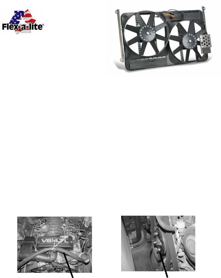
Flex-a-Lite 778 User Manual

Toyota Tundra Electric Fan Kit; 00’–06’
#775 with Controls #778 without Controls
REMOVAL OF EXISTING FAN AND SHROUD ASSEMBLY:
1.Make sure the engine is cool.
2.Disconnect negative (-) battery cable from battery.
3.Remove radiator cap.
4.From under the vehicle;
a.Remove skid-plate mounted to frame and front cross member.
b.Slowly loosen pet-cock to drain approximately 1 gallon of coolant. Note: Drain coolant to a level below upper end of the radiator hose.
c.Remove lower section of the two piece shroud. It is held on by 2ea. metal clips and 2ea. molded plastic hooks.
d.Remove bottom bolts 2ea. holding fan shroud to radiator side brackets. Save bolts for installation of new shroud.
5.From top side of engine compartment, disconnect radiator hose from top of radiator and secure it out of the way.
6.From the air ducting to intake manifold; remove bolt holding A/C return hose, then secure hose out of the way (see Detail 1). Note: bungee cords or long zip-ties work well.
7.Remove coolant overflow hose from radiator filler neck.
8.Remove top bolts 2ea. holding fan shroud to radiator side brackets. Save bolts for installation of new shroud.
9.Remove fan shroud by pulling strait up. Note: Be careful not to scrape against the radiator core.
10.Remove clutch fan assembly by removing 4ea. nuts securing flange to pulley. Re-secure pulley with washers of kit bag #13615 and previously removed nuts (see Detail 2).
Detail 1 |
A/C return line |
Detail 2 |
|
Resecured pully w/ washer kit |
|||
|
|||
|
|
09-02-09 part no. 99777 Page 1 of 5 |

INSTALLATION OF NEW ELECTRIC FAN SHROUD:
You will want to “pre-wire” fan motor wires & Variable Speed Controller (VSC) to new fan shroud before mounting to vehicle.
11. |
Careful planning will save time. Look at the wires |
|
|
coming from the motors. The positives from each |
|
|
motor will be connected together, as will the nega- |
|
|
tives. Drill a ¼” hole through the center brace in the |
|
|
shroud to pass one pair of motor wires through. |
|
|
(see Detail A). |
|
12. |
Place both red motor wires side by side and |
|
|
smoothly twist together. Completely insert pair of |
Detai A |
|
wires into one end of a yellow insulated butt connec- |
tor. Crimp connector to secure. Repeat with black motor wires to another yellow insulated butt connector (see Detail A). Red motor wire is (+) positive and the black is (-) negative.
13.It is easiest to attach the VSC directly onto the front face of the fan shroud. Using the holes in the controller cover for a template, drill two 5/32” holes. Secure the VSC with the two screws provided.
14.Drill two ¼” holes in the shroud where the thick yellow & purple wires from the VSC will pass through to the back side of the shroud (see Detail B & C).
15.IMPORTANT:
Insert yellow wire into the open end of butt connector containing the two red motor wires
and crimp connector securely. Insert purple wire into the open end of butt connector containing the two black motor wires and crimp connector securely. (see Detail C)
16.Mount bracket #77502 to driver’s side and bracket #77501 to passenger’s side of shroud. Use the hex bolts and washers provided.
17.Lower shroud assembly between engine and radiator and loosely mount at top using OEM bolts to original shroud mounting points. Note: Be very careful not to damage core.
18.From under the vehicle;
a. Attach bottom of shroud using OEM bolts to original shroud mounting points and tighten. b. Reinstall protective skid plate.
Detail B |
Detail C |
09-02-09 part no. 99777 Page 2 of 5
 Loading...