

Fishman PREFIX PRO, PRO BLEND INSTALLATION
F
GUITAR BODY
PREAMP
15/8"
ISHMAN
®
P
REFIXPRO
P
REAMPINSTALLATION
/ P
RO
BLEND
WARNING
INSTALLATION BY A QUALIFIED PROFESSIONAL REPAIRMAN IS STRONGLY RECOMMENDED.
FISHMAN TRANSDUCERS WILL NOT BE RESPONSIBLE FOR INSTRUMENTS DAMAGED DUE TO
IMPROPER INSTALLATION.
PARTS
•
Prefix Professional preamp
•
Endpin jack with hardware
•
Adhesive backed wire guides
•
(4) 7/16” self-tapping screws
•
Preamp cut out template
•
(2) Mounting brackets
TOOLS
•
Flex shaft tool with 1” (25.4 mm) diameter cutting wheel or router with 3/16” (6.30 mm) cutter
•
#45 (.082”) drill (for screws)
•
Soldering Iron (30 watt max)
•
Rosin core solder
•
Wire Strippers
•
#1 Phillips screwdriver
•
Variable speed drill
•
Center punch
•
1/8” twist drill
•
15/32” Spade bit drill
•
1/2” open end wrench
•
3/32” Allen wrench or rod
PREPARE THE INSTRUMENT
Prepare the Endblock for the Jack
The objective of this method is to safely drill a hole in the endblock, with the endpin in place. You may remove a loose endpin and refasten it in the endblock with
cyanoacrylate glue before starting the procedure.
1 Apply masking tape around the endblock area to protect the instrument.
2 Locate an X-Acto saw 1/16” away from the body and saw off the endpin.
3 Centerpunch a guide hole in the trimmed endpin.
4 Drill a 1/8” pilot hole through the endpin and endblock.
NOTE: To protect guitars with ornamental veneers around the endblock
(ex: D-45), we recommend enlarging the veneer to size with a hand
reamer after completing this step.
5 Line up 15/32” Spade bit in the pilot hole and begin drilling. Maintain a perpen-
dicular plunge in relation to the instrument. Use steady (but not heavy) pressure,
especially as the drill exits inside the guitar.
6 To avoid damage to the instrument, let the drill come to a complete stop before
removing it from the hole.
NOTE: For solid wood instruments, we strongly recommend gluing plywood reinforcement patches to the screw mounting areas inside the guitar before drilling the screw holes. This will prevent cracking and splintering during installation, as well as provide extra support for the sides
of the instrument.
1 Choose a flat location for the preamp on the side of the instrument. The Flattest
and most comfortable location is often just above the instrument’s waist and well
below the shoulder. Note that the bezel can conform to limited curves on the
sides of Auditorium, Dreadnought and Jumbo instruments.
CAUTION! When mounting the PREFIX PRO on guitars with highly
curved sides (such as small bodied acoustic- electrics), use extreme
caution when choosing the preamp location. A highly curved mounting
surface may cause the preamp to bind on the mounting bezel or in worst
cases, crack the wood around the preamp mounting holes.
2 Locate the enclosed cutout template at the desired location. and cut out the cav-
ity for the preamp .
3 If you are mounting the preamp with wood screws, drill the mounting holes to
.082” (#45”) diameter. If you are mounting the preamp with machine screws and
a metal backing bracket, drill the mounting holes to 7/64” (.109”) diameter.
I
NSTALL THE SYSTEM
Connect the Wires
Precaution:
a. Before cutting the wire lengths, be sure to leave enough slack to allow
full travel of the pivoting preamp.
b. A delicate silver foil enclosure on the back of preamp shields the
pickup terminal connections from hum and noise. When you connect
the pickup wire to the preamp, handle this foil enclosure carefully; do not
to bend or distort its shape.
Cut Out the Preamp Cavity
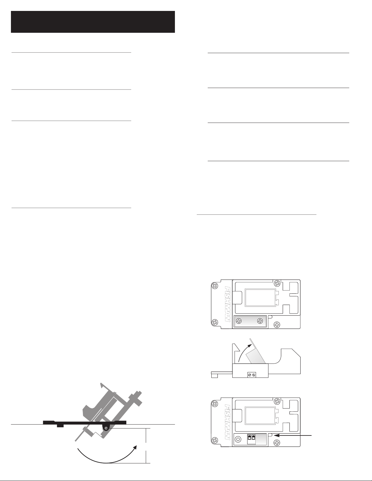
The Prefix Professional preamp can mount without structural alteration to the
instrument, provided that there is at least a clearance of 1-11/16” between the top
and bottom braces in the path of travel of the preamp. This path is defined as a 15/8” radius, with the hinge point on the bezel being the center of the circle. The arc
implied by the travel of the overhanging side of the preamp defines the outside of
the circle.
FOIL SHIELD
TERMINAL BLOCK SCREWS
PICKUP WIRE ENTRY
GROUND WIRE SIGNAL WIRE
F
®
23 4 5 6 71
Black Wire
to Switch
White Wire
to Tip
Shield
to Sleeve
Black Wire
to Switch
White Wire
to Tip
Second Pickup
to Ring
Shield
to Sleeve
ISHMAN
P
REAMPINSTALLATION
®
P
REFIXPRO
/ P
- C
RO
BLEND
ONTINUED
1 With the 9V battery clip facing you, remove the two screws that hold down the
foil shield . Carefully lift the foil up to expose the terminal block. The foil lifts up
from the side closest to the raised FISHMAN logo.
2 Insert the pickup wire in the slot located in the corner between the terminal block
compartment and the battery compartment.
• The ground wire goes to the terminal closest to the FISHMAN logo.
• The signal (hot) wire goes to the terminal further from the FISHMAN logo.
3 Tighten the terminal block screws with a small slotted screwdriver.
4 Pull the slack on the pickup wire until it lays within the terminal block compart-
ment, tucked in behind the screw boss where the wire exits.
5 Check the foil shield sides to make sure that the shape is intact and the corners
are square.
6 Carefully replace the foil enclosure. Note that when properly installed, the foil
enclosure will cleanly surround both the terminal block and one of the screw
bosses. If the sides of the foil jam up on the terminal block or screw boss, adjust
the fit so that the enclosure closes easily.
7 Replace the two screws that hold the foil in place. Be careful not to cross thread
the holes.
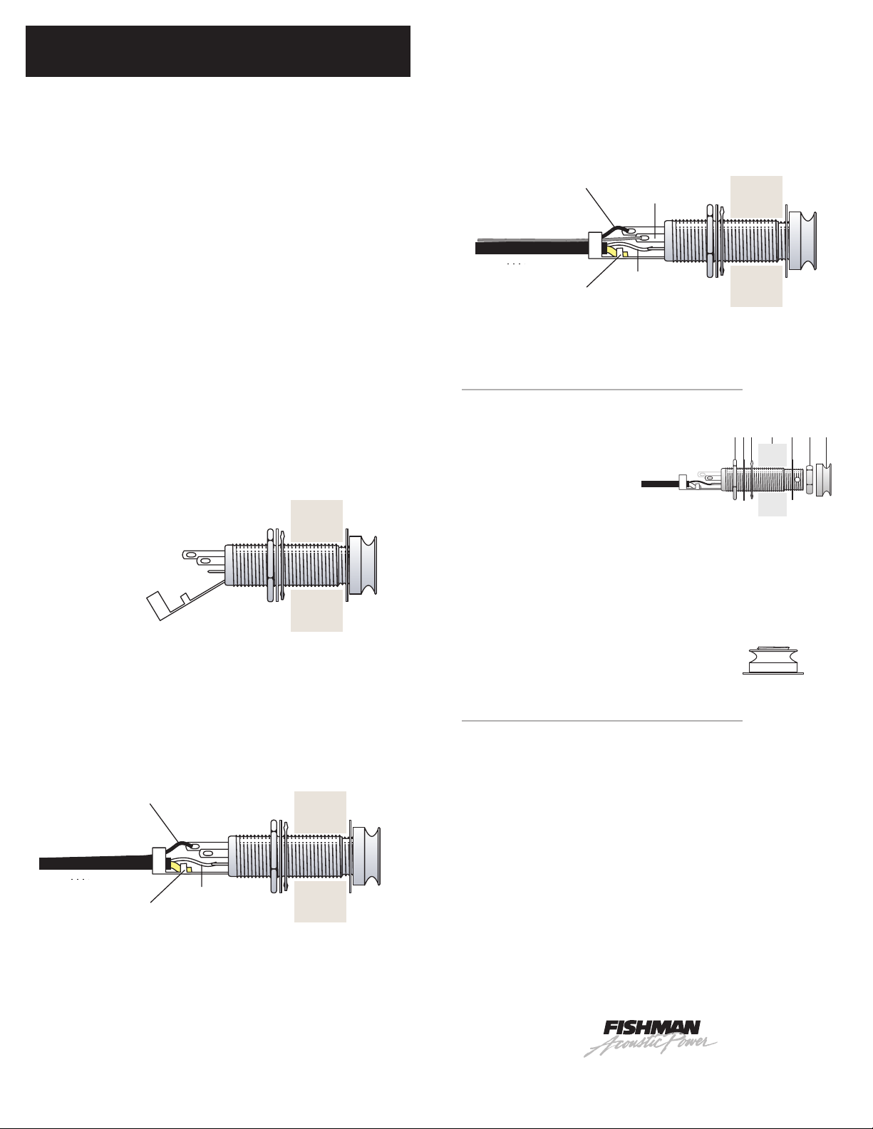
8 Solder the wire ends of the preamp output cable to the terminals on the endpin
jack as illustrated.
Feed the output cable through the endpin hole and connect it to the output jack.
9
To gain better access to the Tip, Ring and Switch terminals, gently bend back the Strain
Relief/Sleeve tab, before you begin to solder.
To add a second pickup in stereo, connect the signal wire from the second pickup to the RING
(middle length( terminal.
INSTALL THE ENDPIN JACK
Follow this sequence when installing the endpin jack:
1 Large hex nut
2 Star washer
3 Large dress washer
4 Guitar end block
5 Small dress washer
6 Small dress nut
7 Strap button
After fitting the small dress washer and the dress nut over the end of the jack, insert
a 3/32” allen wrench through the cross drilled hole on the end of the jack. tighten
the nut with a 1/2” open end wrench while holding the jack in place with the allen
wrench. Thread and hand tighten the strap button.
Note that with the strap button in place, the end of the jack should protrude slightly
to allow proper plug fit.
• Solder the whit wire to TIP (short terminal)
• Solder the black wire to SWITCH (longest terminal)
• Solder the shield wire to SLEEVE (strain relief)
• Leave the RING (middle length) unconnected.
Wiring Options with the Fishman Switchjack
The Switchjack T-R-S-S (Tip/Ring/Sleeve/Switch) stereo switching endpin jack
allows simultaneous stereo operation and battery switching for active pickups. This
new configuration simplifies stereo wiring with many pickup combinations that were
once incompatible.
MOUNT THE PREAMP
1 Angle the preamp 90° from the bezel and insert in the cut-out.
2 Fasten the screws with a #1 Phillips driver. Do not over tighten.
3 Install a 9 volt alkaline battery.
4 To keep the wires inside the guitar from rattling, secure the to the adhesive
backed plastic wire guides. Attach the wire guides to the sides or the kerfed lining of the instrument.
F
340-D Fordham Road Wilmington MA 01887 USA
Phone 978-988-9199 • Fax 978-988-0770 www.fishman.com
ISHMAN
T
RANSDUCERS
3-0 0 • 009-089-002
 Loading...