

Page 1
M
ODEL
VMV
Vintage Mount Vibrato Style
Bridge / Pickup System
for “six-screw” bridge Stratocaster-style guitars
TM
INSTALLATION BY A QUALIFIED PROFESSIONAL REPAIRMAN IS STRONGLY
RECOMMENDED. FISHMAN TRANSDUCERS WILL NOT BE RESPONSIBLE FOR
ANY DAMAGES THAT MAY RESULT FROM IMPROPER INSTALLATION.
The Fishman Powerbridge™ Pickup is warranted to function for a period of One (1) Year
from the date of purchase. If the unit fails to function properly within the warranty period,
free repair and the option of replacement or refund in the event that Fishman is unable
to make repair are Fishman’s only obligations.This warranty does not cover any consequential damages or damage to the unit due to misuse, accident, or neglect. Fishman
retains the right to make such determination on the basis of factory inspection. Products
returned to Fishman for repair or replacement must be shipped in accordance with the
Return Policy, as follows. This warranty remains valid only if repairs are performed by
Fishman. This warranty gives you specific legal rights and you may also have other
rights which may vary from state to state.
RETURN POLICY
To return products to FISHMAN TRANSDUCERS, you must follow these steps...
1. Call FISHMAN TRANSDUCERS at 978-988-9199 for a Return Authorization Number
(“RAN”).
2. Enclose a copy of the original Bill of Sale as evidence of the date of purchase, with
the product in its original packaging and a protective carton or mailer.
3. FISHMAN TRANSDUCERS’ technicians will deter mine whether the item is covered
by warranty or if it instead has been damaged by improper customer installation or
other causes not related to defects in material or workmanship.
4. Warranty repairs or replacements will be sent automatically free of charge.
5. If FISHMAN TRANSDUCERS determines the item is not covered by warranty, we
will notify you of the repair or replacement cost and wait for your authorization to
proceed.
Fishman's bridge system fits on the Fender Stratocaster® guitar or Fender Telecaster® guitar and other similar and comparable guitars. • FENDER,
STRATOCASTER, STRAT, AMERICAN STANDARD STRAT, AMERICAN STANDARD TELE, TELE are registered trademarks of Fender Musical
Instruments Corp. with which Fishman Transducers Inc. is not affiliated.
F
ISHMAN
P
OWERBRIDGE
™ P
ICKUP
I
NSTALLATION
G
UIDE
POWERBRIDGE
™
PICKUP
M
ODEL
VMV
Vintage Mount Vibrato Style
Bridge / Pickup System
POWERBRIDGE
™
PICKUP
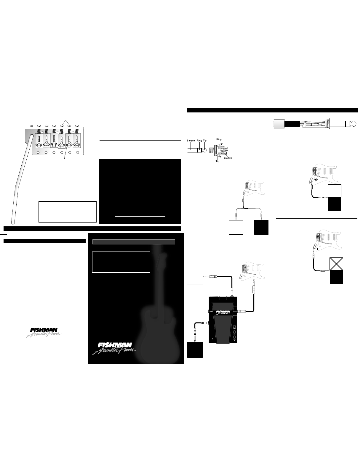
• Stereo Jack
(included)
A 1/4" stereo output jack is provided with your Powerbridge™ Pickup. It is an
essential component to the Powerbridge™ System.
It can send piezo and magnetic pickup signals to separate amplifiers. The
magnetic pickups are wired to
Tip, and the Powerbridge™
Pickup is wired to Ring.
• Instrument
Cable
(not
included)
Depending on how you want to
set up your Powerbridge™
system, you can use one of the following three instrument cables (available from
your Fishman dealer).
1 - Stereo "Y" Cable
This will split the
Powerbridge™ and magnetic
pickup signals and send them
to separate amplifiers or other
destinations (PA, recording
devices, etc.).
2 - Stereo Instrument
Cable
Both magnetic and piezo
signals can be sent through a
single stereo instrument cable
to one of our outboard
Powertronics™ preamps. From there, magnetic and piezo signals can be either
combined to a single mono output or split to separate stereo outputs.
NOTE: For best results, use a "2 Pair" premium stereo cable (available through
your Fishman dealer) with separate shielding for both the Powerbridge™ and
magnetic signals.
3 - Mono Instrument Cable
With a Fishman Powerchip™:
A standard mono instrument cable used
with a Fishman Powerchip™ will provide a combined Powerbridge™ / magnetic
pickup signal.
Without a Fishman Powerchip™:
A mono instrument cable will short out
the Powerbridge™ Pickup, but your magnetics will function
exactly
as they did
before you installed the Powerbridge™.
• Basic Passive Setup
Stereo Outputs
The simplest way to get the Powerbridge™ Pickup up and running is to simply wire it
and the magnetic pickups to Tip/Ring outputs of the supplied stereo jack. A stereo
"Y" cable or a standard stereo cable can then carry the two signals. From there, all
mixing and blending functions will be performed offboard the instrument. A Fishman
Powerblend™ Pedal is especially suited f or offboard b lending/mixing with this passiv e
setup.
For a passive setup, you don't want to tie the Powerbridge™ and magnetic pickup
wires together at the guitar's mono output jack. This may seem like a good idea, but
it won't work. If you connect the piezo and magnetic outputs, you will experience a
loss of tone and a very bizarre and un-musical interaction between the Powerbridge™
and magnetic pickups.
Magnetic and piezo pickups operate on different electrical platforms. Magnetics are
"inductors" and piezos are "capacitive" devices. The solution is to electronically
isolate or "buffer" the two signals with an active mixing circuit like the Fishman
Powerchip™.
Thank you for choosing the Powerbridge™ pickup. You will find that there are
several wiring options available for the Powerbridge™. To help you decide how
to integrate it with your Strat
®
-Style guitar, please read the Powerbridge™ Users
Guide that accompanies these instructions.
Parts List
System Components
•
VMV Powerbridge™ Pickup
•
6 Pivot screws
•
1.5 mm hex wrench
•
Vibrato claw & springs
•
Vibrato arm
•
2 Vibrato Mounting Screws
•
Stereo output jack
•
Shielding foil
•
5 M
Ω
resistor
•
Routing T emplate
Important!
Do not disturb the black signal wires located under the
saddles. They are extremely delicate. Pickup failure may
result from handling these wires.
Powerbridge™ installation should be performed by a
qualified repairman only. Fishman Transducers will not be
responsible for any damages that may result from improper
installation.
The VMV Powerbridge™ is a direct replacement for Fender
®
Stratocasters®with a 2.22" (E to E, center to center) pivot
screw spacing. Note that some non-USA Strats
®
have a
smaller pivot screw spacing and will require plugging and
re-drilling these holes to "vintage" Fender
®
specifications.
Please read these instructions carefully. For technical
assistance, contact Fishman Customer Support at
978-988-9665 or tech@fishman.com
L
IMITED
W
ARRANTY
I
NSTALLATIONGUIDE
FISHMAN TRANSDUCERS, INC.
340-D Fordham Road Wilmington MA 01887 USA
Phone 978-988-9199 • Fax 978-988-0770
www.fishman.com
009-075-005 • Rev 3 • 4-18-02
TM
F
ISHMAN
P
OWERBRIDGE
™ P
ICKUPINSTALLATION
G
UIDE
Intonation
Screws
Saddle Height
Adjustment Screws
Tremolo Bar
Tension Adjust
Stereo Output Jack
(Tip/Ring/Sleeve)
Stereo "Y" Cable
Powerbridge™
Signal
(Ring)
Pure
Magnetic
Signal
(Tip)
Powerbridge™
Stereo
Instrument Cable
to Stereo Input
Magnetic
Powerchip™
Mono Instrument Cable
Powerbridge™
Magnetic
Optional Passive
Volume Pot
Mono Instrument Cable
Stereo Output Jack
(Tip/Ring/Sleeve)
Powerbridge™
Magnetic
Page 2
Wiring Instructions
• Preliminary Notes
To prevent 60 Hz hum, the entire Powerbridge™ Pickup signal path should be fully shielded.The control cavity, jack cavity, and any non-conductive surface to which the controls
are mounted (such as a plastic pickguard) must be shielded with adhesive-backed foil or conductive paint.The shielded cavities should then be grounded.
For complete hum prevention, the included stereo jack must also be shielded. To do this, we’ve included a piece of shielding foil. Note that one side is insulated. After you have
soldered the wires to the jack, roll the foil into a tube so that the insulation is on the INSIDE and surround the stereo jack with the tube. Connect the foil side of the tube to ground
by soldering it to the shielding of the Powerbridge™ Pickup wire or to a jumper that is connected to any ground.
If your instrument has active magnetic pickups (requiring an onboard battery), you will need a special 9 Pin Switching Jack (Fishman Part Number ACC-PBR-9PJ), available
through your Fishman dealer.
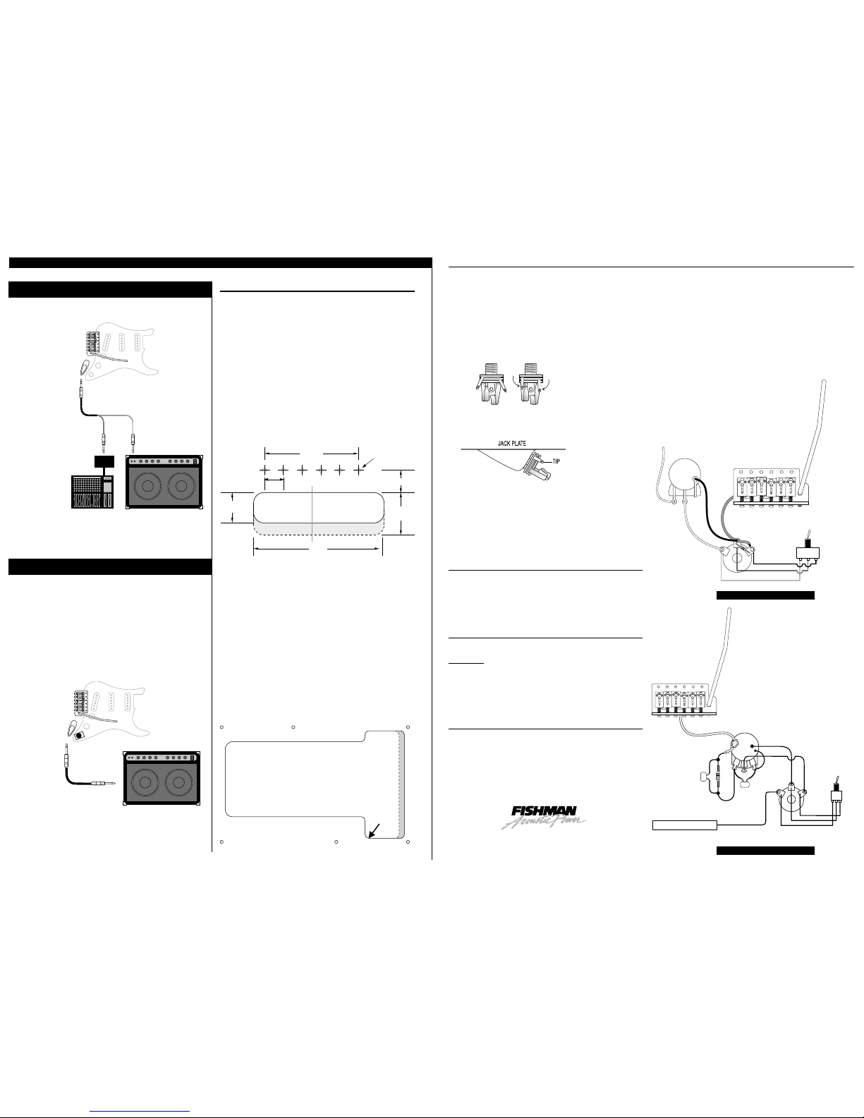
• Install the Stereo Jack
The jack can fit into the jack cavity without removing wood ...
1 Bend the terminals of the included stereo jack toward its center. See Fig 3
2 Rotate the jack to locate the Tip terminal exactly at the upper left side of the jack plate recess.
See Fig 4
• Wiring Options
There are several different ways to wire the Powerbridge™.
Choose the option that best suits your needs.
Powerbridge™ & Magnetic Pickups wired directly
to a Stereo Jack
1. Connect the Powerbridge™ signal wire directly to the Ring terminal on the supplied
stereo jack.
2. Connect the Powerbridge™ and magnetic grounds to the Sleeve terminal.
3. Connect the magnetic signal wire to the Tip terminal.
4. Connect the included 5 M
Ω
resistor between the ring and sleeve terminals.
Passive Volume for the Powerbridge™
This circuit that is easily assembled from "stock" guitar pots and components available at any electronics parts retailer.
Y
ou will need:
• 250 k audio taper pot
• 330k resistor
• 820 pF capacitor
• 1500 pF capacitor
This network will attenuate the Powerbridge™ so that it better matches levels
between magnetic and piezo pickups. You can expect a 14 dB (nominal) decrease in
Powerbridge™ output with this circuit.
NOTE: Optional 3-Way Selector Switch -
If desired, a single pole, double
throw (spdt) 3-way switch can also be added for piezo/magnetic pickup selection.
Use a switch with an ON-OFF-ON orientation (no, this is not a misprint)
NOTE: Active Onboard Blending
A Fishman Powerchip™ (not included) must be installed if you wish to blend/mix
piezo and magnetic signals onboard the instrument.
250K - 300K
Audio Taper Pot
Sleeve
Ring
Tip
1500 pF1500 pF
330 K820 pF
Magnetic Signal
Optional 3-W
Selector Swit
Mag
Both
Piezo
O
N
O
F
F
O
N
Stereo
Output
Jack
• Active Setup - Powerchip™
With our onboard Powerchip™, you can mix and combine both the Powerbridge™
and magnetic pickups (on the guitar) and plug right into a single channel guitar
amplifier. You can also instantly split signals by simply changing to a stereo cable or
stereo "Y" cable.
See the Powerbridge™ System Users Guide
for Powertronics™ descriptions.
Bridge Installation
• Strat®Style Guitars
The VMV Powerbridge™ is a direct replacement for Fender
®
Stratocasters®with a 2.22" (E to E, center to center) pivot screw
spacing. Note that some non-USA Strats®have a smaller pivot screw
spacing and will require plugging and re-drilling these holes to
"vintage" Fender
®
specifications. See Fig 1
• Instrument Builders
Refer to the enclosed drilling template to locate the six (6) pivot screw
holes.
• Routing the Powerbridge™
Pickup Wire
•
With a 3/32” (2.4 mm) aircraft bit, drill a hole from the vibrato cavity
to the control cavity.
•
Route the Powerbridge™ Pickup wire through this hole. See Fig 2
If you prefer, you may route the Powerbridge™ Pickup wire through
the guitar's ground wire channel. If you do so, secure the
Powerbridge™ Pickup wire so that it cannot be pinched by the
springs or the bridge block.
F
ISHMAN
P
OWERBRIDGE
™ P
ICKUPINSTALLATION
G
UIDE
FISHMAN TRANSDUCERS
®
340-D Fordham Road Wilmington MA 01887 USA
Phone 978-988-9199 • Fax 978-988-0770
www.fishman.com
TM
2.220"
(56.38 mm)
.444"
(11.29 mm)
3.085"
(78.35 mm)
1"
(25.4 mm)
.705"
(17.9 mm)
.535" (13.58 mm)
7/64" (2.75 mm)
Diameter Holes
Center Line of Guitar
FIG 1 - Locate the 6 pivot screws
Drill 3/32"
(2.4 mm) Hole
from Vibrato Cavity
to Control Cavity
FIG 2 - Hole for Powerbridge™ Signal Wire
Stereo OutputJack
(Tip/Ring/Sleeve)
Electric Guitar Amp
Active
D.I.
PA / Recording Console
Pure Magnetic Signal
(Tip)
Powerbridge™ Signal
(Ring)
Powerchip™
Mono Instrument Cable
Passive Setup
Active Setup
FIG 3 - Bend Jack Terminals
FIG 4 - Align Tip Terminal
Magnetic
Volume
Sleeve
Ring
Tip
Magnetic
Signal
Stereo Jack
Optional 3-Way
Selector Switch
Mag
Both
Piezo
ON ONOFF
Passive Volume
Direct Wiring
 Loading...