

Page 1
OWNER’S MANUAL
Powerblend
SS tt ee rr ee oo BB ll ee nn dd ii nn gg PP ee dd aa ll
SS tt ee rr ee oo BB ll ee nn dd ii nn gg PP ee dd aa ll
®
For Use With Electric Guitars Equipped With The
For Use With Electric Guitars Equipped With The
Fishman Powerbridge System And All Other Stereoeo
Fishman Powerbridge System And All Other Ster
Output Electric Guitars
Output Electric Guitars
Page 2
Powerblend
Thank you for purchasing this accessory for the Fishman Powerbridge system. We are confident that the Powerblend will greatly enhance the performance and utility of your
Powerbridge system. Please read these instructions carefully. If you have any questions or
problems, contact Fishman Customer Service at 978-988-9665.
The Fishman Powerblend is an active stereo blending floor pedal, optimized for electric guitars equipped with the Fishman Powerbridge. The Powerblend provides the perfect interface between the Powerbridge, the guitar’s magnetic pickups and single or multiple audio
destinations.
The silent action volume pedal permits hands free control of the Powerbridge volume and
facilitates quick changes between magnetic and piezo pickups. Dedicated Powerbridge EQ,
as well as four essential output options provide the missing link for the Powerbridge/magnetic pickup signal chain.
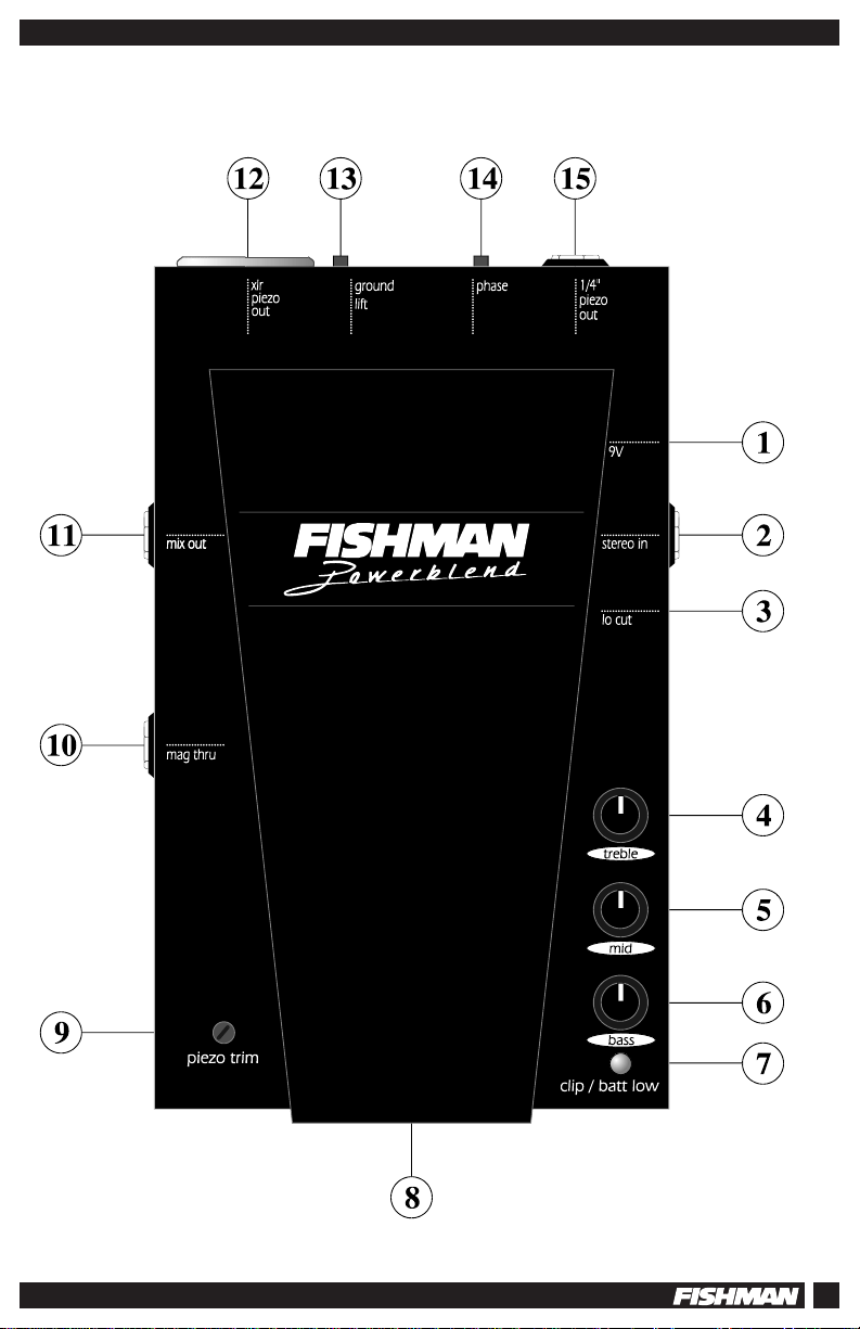
FEATURES
1. 9V AC Adapter Input
2. Stereo Input Jack
3. Lo Cut Filter
EQ Section
(Powerbridge signal only)
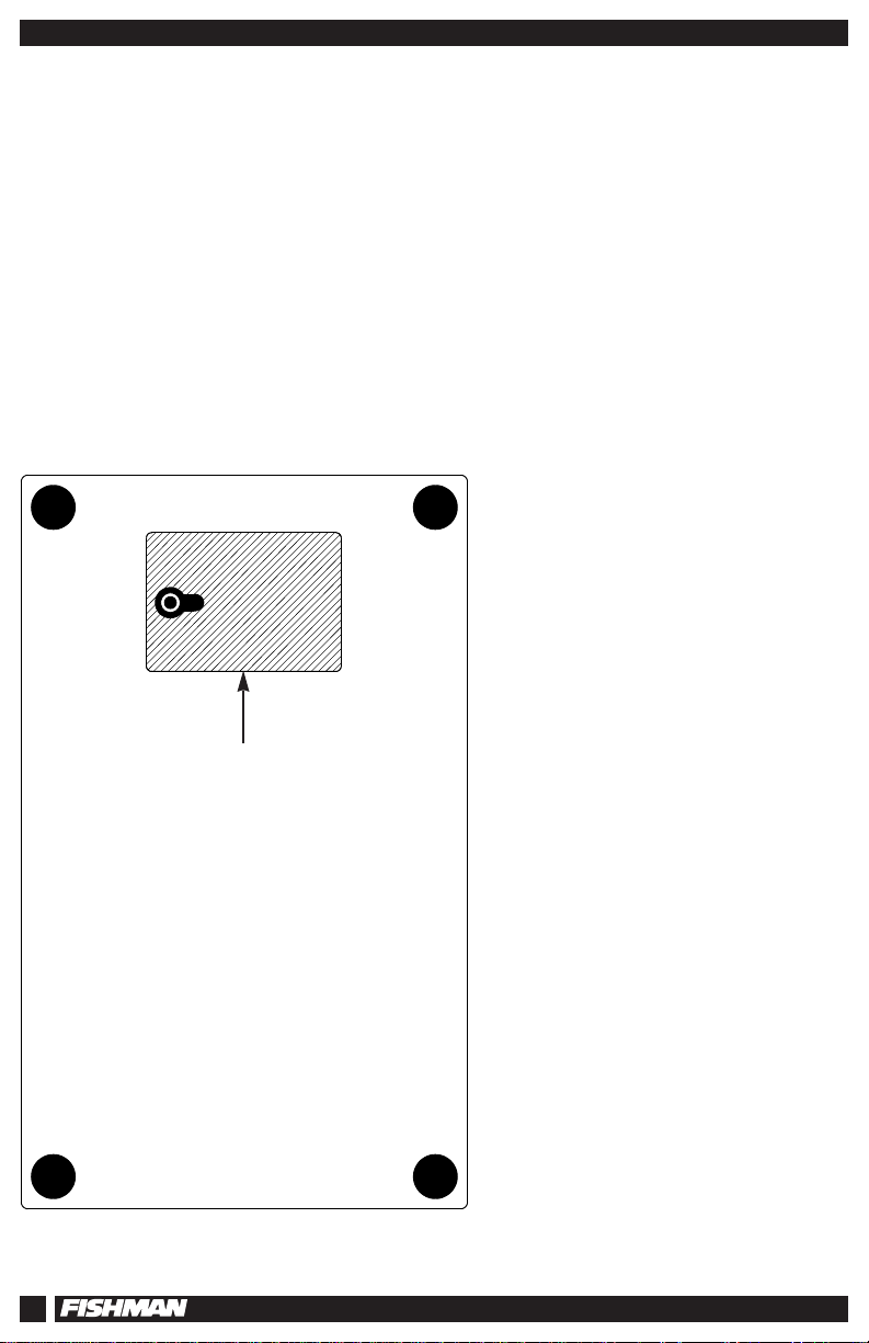
NOTE: 9 Volt battery access is
located on the bottom of the unit.
2
4. Treble Control
5. Midrange control
6. Bass Control
7. Clip / Battery low LED
8. Blend Pedal
9. Piezo Trim
10. Magnetic Thru Jack
11. Mix Output Jack
12. XLR Piezo Output Jack
13. Ground Lift
14. Phase Switch
15. 1/4” Piezo Output Jack
Page 3
Stereo Blending Pedal
3
Page 4
MAGNETIC
VOLUME
SLEEVE
POWERBRIDGE
VOLUME
(OPTIONAL)
POWERBRIDGE
RING
TIP
330 pF
5M
Ω
1
2
3
MAGNETIC
SIGNAL
STEREO JACK
MAGNETIC
VOLUME
POWERBRIDGE
MAGNETIC
SIGNAL
SLEEVE
RING
5M
Resistor
Ω
TIP
STEREO JACK
Powerblend
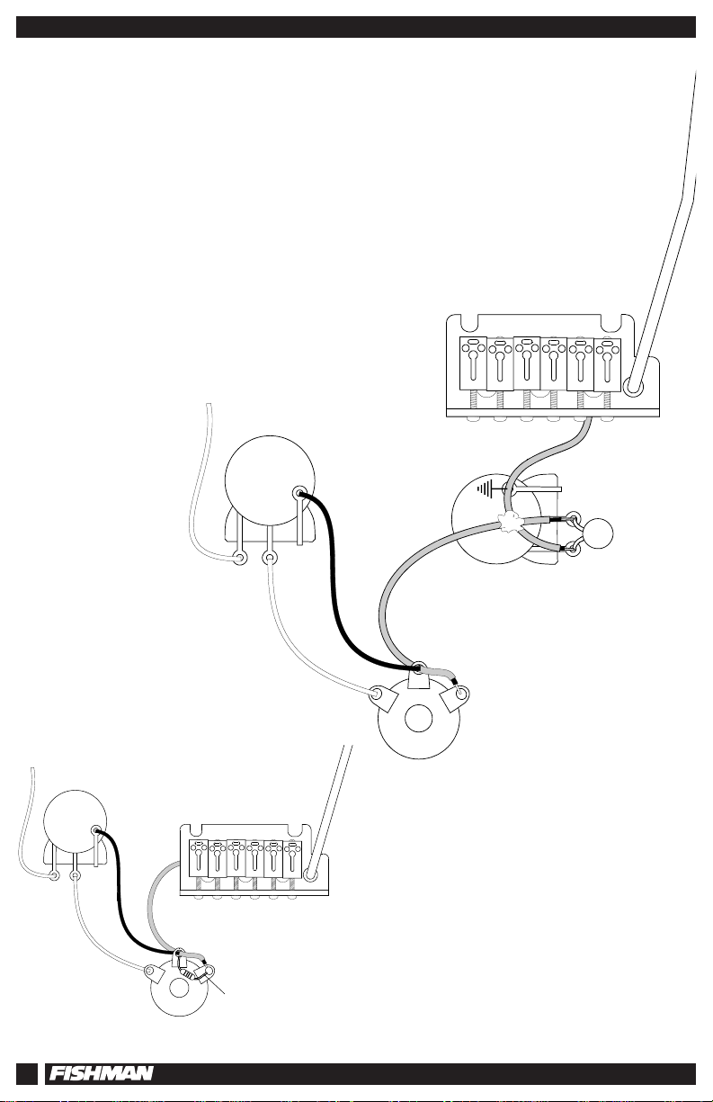
PREPARING YOUR INSTRUMENT FOR THE POWERBLEND
Before you begin using your Powerblend, you need to have the magnetic and
Powerbridge pickups in place on your guitar.
Wire the guitar to a stereo output jack as follows:
1. Route the magnetic pickups' signal to the TIP terminal.
2. Route the magnetic pickups' ground to the SLEEVE terminal.
3. Route the Powerbridge signal to the RING terminal.
4. Route the Powerbridge ground to the SLEEVE terminal.
4
NOTE: If you decide to wire the
Powerbridge directly to the output jack
without a volume control, you must wire a 5
M
Ω
resistor between the Ring and Sleeve
terminals on the instrument's output jack.
Page 5

Stereo Blending Pedal
FUNCTIONS
BATTERY POWER
Make note of the following when using the Powerblend under battery power:
• The Powerblend has no on/off switch. Under battery power, the Powerblend is turned on when the
STEREO IN jack is plugged in.
• The Powerblend pedal is always on when using an AC adapter.
• To avoid excessive batter y drain, unplug the STEREO IN jack when the unit is not in use (battery life
is an estimated 55 hours, continuous use).
BATTERY COMPARTMENT
To install the batter y (see page 3) slide the latch on the battery compartment to the right and remove
the door. Install a fresh 9 Volt alkaline battery in the batter y clip.
AC ADAPTER INPUT
USE ONLY a FISHMAN model 910-R or a Roland PSA series Regulated AC Adapter.
Using an unregulated power supply will void the warranty and may damage the unit.
STEREO IN JACK
The STEREO IN jack is a TRS (Tip/Ring/Sleeve) 1/4" input that accepts two discrete signals through
a stereo instrument cable.
Route the magnetic pickup signal to the Tip terminal and route the Powerbridge (Piezo) signal to the
Ring terminal of this jack.
Use the included stereo cable to connect your guitar to the Powerblend.
LO CUT FILTER
This switch lets you select between three distinct voicings for the Powerbridge pickup.
TOP POSITION (Flat)
For full frequency response, select the top position.This works best with hard-tail style
Powerbridges, especially through a full range sound system.
MIDDLE POSITION (Bass Cut)
Gently rolls off the low end. The Bass Cut position slightly subdues bass and unmasks
mids and highs.
BOTTOM POSITION (Deep Bass Cut)
Use the bottom position for all vibrato style Powerbridges. This setting "trims the fat" by cutting
sub-bass frequencies. The Deep Cut will minimize rumble and handling noise on vibrato style
guitars. It will also provide "woofer insurance" by limiting low frequency cone excursion when
using the vibrato arm.
5
Page 6

Powerblend
• PIEZO EQUALIZATION
BASS and TREBLE CONTROLS
These are boost/cut shelving tone controls. They affect only the piezo (Powerbridge) signal
appearing at the Ring input of the STEREO IN jack.
MIDRANGE CONTROL
This is a resonance style boost/cut tone control. It affects only the piezo signal appearing at
the Ring input of the STEREO IN jack.
CLIP / LOW BATTERY INDICATOR
When plugging into the POWERBLEND, the Low batter y LED will flash momentarily, indicating that
the power is on. When the Low Battery LED stays on with the Input jack plugged in, it's time to
change the battery.The LED will also flash when the Piezo Input is overloaded (clipping). In these
cases, lower the Piezo Trim until the light stops flashing.
PIEZO (POWERBRIDGE) BLEND PEDAL
Depressing the pedal adds the signal from the Powerbridge to the MIX OUT, XLR PIEZO OUT, and
the 1/4” PIEZO OUT.
PIEZO TRIM
Sets the piezo level relative to the magnetic pickups' level. Use this to balance the Powerbridge with the
guitars' magnetic pickups. Also, use this control to attenuate a clipped (distor ted) piezo signal.
MAGNETIC THR U JACK
A direct unbuffered signal from the guitar’s magnetic pickups appears at this output. Plug this into
the input of a guitar amplifier for unaffected magnetic pickup sound.
MIX OUT JACK
A combination of buffered magnetic pickup and Piezo Pickup signals appear at this instrument level
output. Use the Mix Out when you are limited to one input source for both piezo (Powerbridge) and
magnetic pickups. Typically the MIX OUT goes to a single channel instrument amp or a direct box.
XLR PIEZO OUTPUT
An electronically balanced, instrument level signal from the Powerbridge appears at this output.
For best results, plug this into an acoustic instrument amp or PA system.
GROUND LIFT SWITCH
This switch removes pin #1 from the XLR PIEZO OUTPUT. Use this switch to minimize ground loop
hum between the Powerblend and other audio devices.
PIEZO PHASE SWITCH
This switch reverses the phase relationship 180 degrees between the Powerbridge and magnetic pickups. If you experience a volume loss when combining the Powerbridge with the guitars' magnetic pickups, flip this switch to correct the phase relationship between the two.
1/4" PIEZO OUTPUT JACK
An unbalanced, buffered, instrument level signal from the Powerbridge appears at this output.
For best results, plug this into an acoustic instrument amp or PA system.
6
Page 7

Stereo Blending Pedal
SUGGESTED SIGNAL ROUTING OPTIONS
Powerbridge and magnetic pickups to a single channel amp.
7
Page 8

Powerblend
piezo trim
clip / batt low
bass
mid
treble
STEREO
INSTRUMENT CABLE
from STEREO INPUT
MONO INSTRUMENT
CABLE from
MAG THRU
MONO INSTRUMENT
CABLE from
1/4" PIEZO OUT
ELECTRIC GUITAR
with FISHMAN POWERBRIDGE
2 CHANNEL ELECTRIC
GUITAR AMP
SUGGESTED SIGNAL ROUTING OPTIONS
Powerbridge and magnetic pickups to separate channels of a single amp.
8
Page 9

Stereo Blending Pedal
SUGGESTED SIGNAL ROUTING OPTIONS
Powerbridge and magnetic pickups to two separate amps
9
Page 10

Powerblend
SUGGESTED SIGNAL ROUTING OPTIONS
Powerbridge to a PA and magnetic pickups to a guitar amp.
(Illustration showing guitar, stereo cord, POWERBLEND, cord from MAG THRU to a guitar
amp. Cord from XLR PIEZO OUT to a PA).
10
Page 11

Stereo Blending Pedal
SPECIFICATIONS
Nominal Input Levels
Piezo (Powerbridge) -10 dBV
Magnetic -10dBV
Inputs Overload Level +10 dBV
Input Impedances
Magnetic
Mix Out buffer: 1 M
Mag Thru: Unaffected
Piezo Proprietary
Nominal Output Levels and Impedances
Magnetic Thru -10 dBV
1/4” Piezo Out -12 dBv (1 k
Mix Out -5 dBV (1 k
Piezo XLR Out -6 dBV (600
Outputs Overload Level +12 dBV (+18 dBV for Piezo XLR Out)
Bass Control Range ± 11 dB at 80 Hz
Mid Control Range ± 12 dB at 1.1 kHz
Treble Control Range ± 12 dB at 10 kHz
THD Less than .02%, -10 dBV input
Signal to Noise Ratio 91 dB (A weighted referred to nominal -10 dBV input)
Power Supply 9V alkaline battery (estimated 55 hours continuous use)
Current Draw 9 mA
Dimensions 5.5” width x 9” deep x 2” tall
Ω
Ω
)
Ω
)
Ω
)
± 3 dB at 350 Hz
± 3 dB bandwidth 1.3 kHz
± 3 dB at 2.4 kHz
Regulated Fishman 910-R 9V AC Adapter
All specifications subject to change without notice
BLOCK DIAGRAM
11
Page 12

Limited Warranty
The FISHMAN POWERBLEND is warranted to function for a period of One (1) Year from the
date of purchase. If the unit fails to function properly within the warranty period, free repair
and the option of replacement or refund in the event that FISHMAN is unable to make
repair are FISHMAN’s only obligations. This warranty does not cover any consequential
damages or damage to the unit due to misuse, accident, or neglect. FISHMAN retains the
right to make such determination on the basis of factory inspection. Products retur ned to
FISHMAN for repair or replacement must be shipped in accordance with the Return Policy,
as follows.This warranty remains valid only if repairs are performed by FISHMAN. This
warranty gives you specific legal rights and you may also have other rights which may vary
from state to state.
RETURN POLICY
To return products to FISHMAN TRANSDUCERS, you must follow these steps...
1. Call FISHMAN TRANSDUCERS at 978-988-9199 for a Retur n Authorization Number
(“RAN”).
2. Enclose a copy of the original Bill of Sale as evidence of the date of purchase, with
the product in its original packaging and a protective carton or mailer.
3. FISHMAN TRANSDUCERS’ technicians will determine whether the item is covered by
warranty or if it instead has been damaged by improper customer installation or other
causes not related to defects in material or workmanship.
4. Warranty repairs or replacements will be sent automatically free of charge.
5. If FISHMAN TRANSDUCERS determines the item is not covered by warranty, we will
notify you of the repair or replacement cost and wait for your authorization to proceed.
FISHMAN TRANSDUCERS
340-D Fordham Road Wilmington MA 01887 USA
Phone 978-988-9199 Fax 978-988-0770
009-025-001 1-98
www.fishman.com
®
 Loading...