


ACTIVESMART™ INTEGRATED
FRENCH DOOR REFRIGERATOR FREEZER
RS6A80 models
INSTALLATION GUIDE
US CA
84418C07.20


Safety and warnings 2
Components 3
Tools 5
Appliance and cavity dimensions 6
Cabinetry options 7
Stainless steel door panel and toe kick dimensions 8
Custom door panel and toe kick dimensions 9
Custom door panel installation dimensions 10
Custom door panel installation template 11
Door clearance 12
Electrical and plumbing 13
Before installation 15
Cavity preparation 17
Water and power supply connection 18
Top trim installation 19
Side brackets installation 20
Positioning into cabinetry 21
Aligning inside cabinetry 22
Door panel installation - stainless steel 23
Door panel installation - custom 27
Fixing to cabinetry 33
Water filter installation 34
Toe kick installation 35
Door and door trims installation 37
Cabinet trims installation — [A] Flexible spring clip method 38
Cabinet trims installation — [B] Fixed screw method 40
Final checklist 42
CONTENTS
1
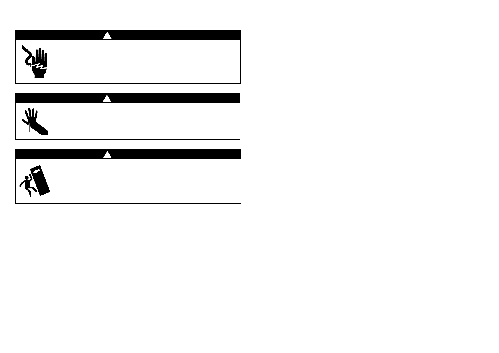
SAFETY AND WARNINGS
!
WARNING!
Electric Shock Hazard
Read and follow the safety and warnings outlined in this installation
guide before operating this appliance.
Failure to do so can result in death, electric shock, fire or injury
topersons.
!
WARNING!
Cut Hazard
Take care—panel edges are sharp. Failure to use caution could result
ininjury or cuts.
!
WARNING!
This appliance is top-heavy and must be secured to prevent the
possibility of tippingforward.
To ensure that the appliance is stable under all loading conditions,
theanti-tip bracket and fittings supplied must be installed according
tothe following installation instructions by a professional installer.
READ AND SAVE THIS GUIDE
●
It is very important for the installer to follow the instructions in this installation guide
to ensure proper installation and operation of the appliance. Ensure that you read the
installation guide thoroughly and understand all information.
●
The water connection to your Ice and water appliance must be installed by an
authorized plumber or Fisher & Paykel trained and supported service technician
andcomply with all state and local laws.
●
Installation and use MUST comply with all state and local plumbing codes.
Checkwithyour local public works department for plumbing codes.
You must follow their guidelines as you install the water filtration system.
●
To avoid serious illness or death, only connect your water filter to safe drinking water.
●
The water filter cartridge needs to be changed when the replacement indicator icon
illuminates. This will happen every 6 months.
●
If the water filtration system has been allowed to freeze, replace filter cartridge.
Failureto replace the disposable filter at recommended intervals may lead to reduced
filter performance and failure of the filter, causing property damage from water leakage
or flooding.
●
In cases of excessively reduced filter life—we recommend that you consult a local
plumber or your water supplier for advice on suitable filtration requirements for the
water supplied to your home.
●
Filter replacement is the consumer’s responsibility and will not be covered by the
warranty except in the case of faulty parts or materials within the filter cartridge.
●
If the water has not created ice for some time or ice has an unpleasant taste or odor
dispose of ice and refer to the flushing instructions detailed in the installation section
of this user guide/installation guide. If unpleasant taste or odor persists, you may wish
to fit a new filter cartridge.
●
Use new tubing supplied with the appliance. DO NOT reuse old tubing from old water
and ice connections.
●
Your water filtration system can withstand up to 120psi (827kPa) of water pressure.
Ensure the supplied pressure reducing valve is installed before installing the water
filtration system. DO NOT install if water pressure exceeds 120psi (827kPa).
To reduce the risk associated with property damage due to water leakage or flooding:
●
DO NOT install systems in areas where ambient temperatures may go above 100°F
(38°C) or drop below 33°F (0.6°C).
●
DO NOT install on hot water supply lines. The maximum operating water temperature
of this filter system is 100°F (38°C).
●
DO NOT install where water hammer conditions may occur. If water hammer conditions
exist, you must install a water hammer arrester.
WARNING!
To reduce the risk associated with choking:
●
DO NOT allow children under 3 years of age to have access to small parts during the
installation of the water filter.
2
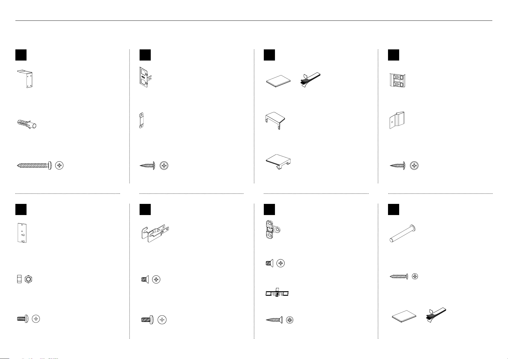
Internal box (Installation kit)
Located inside the appliance
COMPONENTS
Anti-tip bracket
A
assemblykit
Anti-tip bracket
(1)
Masonry plug
(4)
10x40 cross-head screw
(4)
Top trim
E
install kit
Door panel
B
attachmentkit
Side bracket
(10)
Side strap
(10)
8x16 mush washer (Custom) screw
(36)
Side bracket
F
install kit
Door/drawer trim
C
installkit
Dual adhesive tabs (6 per each strip)
(12)
Side cover
(4)
Top cover
(2)
Fixing bracket
G
install kit
Cabinet side trim
D
installkit
Side trim bracket
(6)
Spring clip
(6)
8x16 mush washer screw
(12)
Miscellaneous
Z
components
Cabinet top trim bracket
(2)
M5 nut
(4)
M5x8 cross-head screw
(4)
Side base brackets (right/left)
(2)
M5x8 countersunk cross-head screw
(4)
M5x10 cross-head screw
(10)
Fixing bracket
(4)
M5x8 countersunk cross-head screw
(8)
Screw cover
(4)
#8x19 twin thread screw
(8)
Hinge limiting pin
(1)
#8x16 panhead screw
(3)
Dual adhesive tabs (6 per each strip)
(6)
3
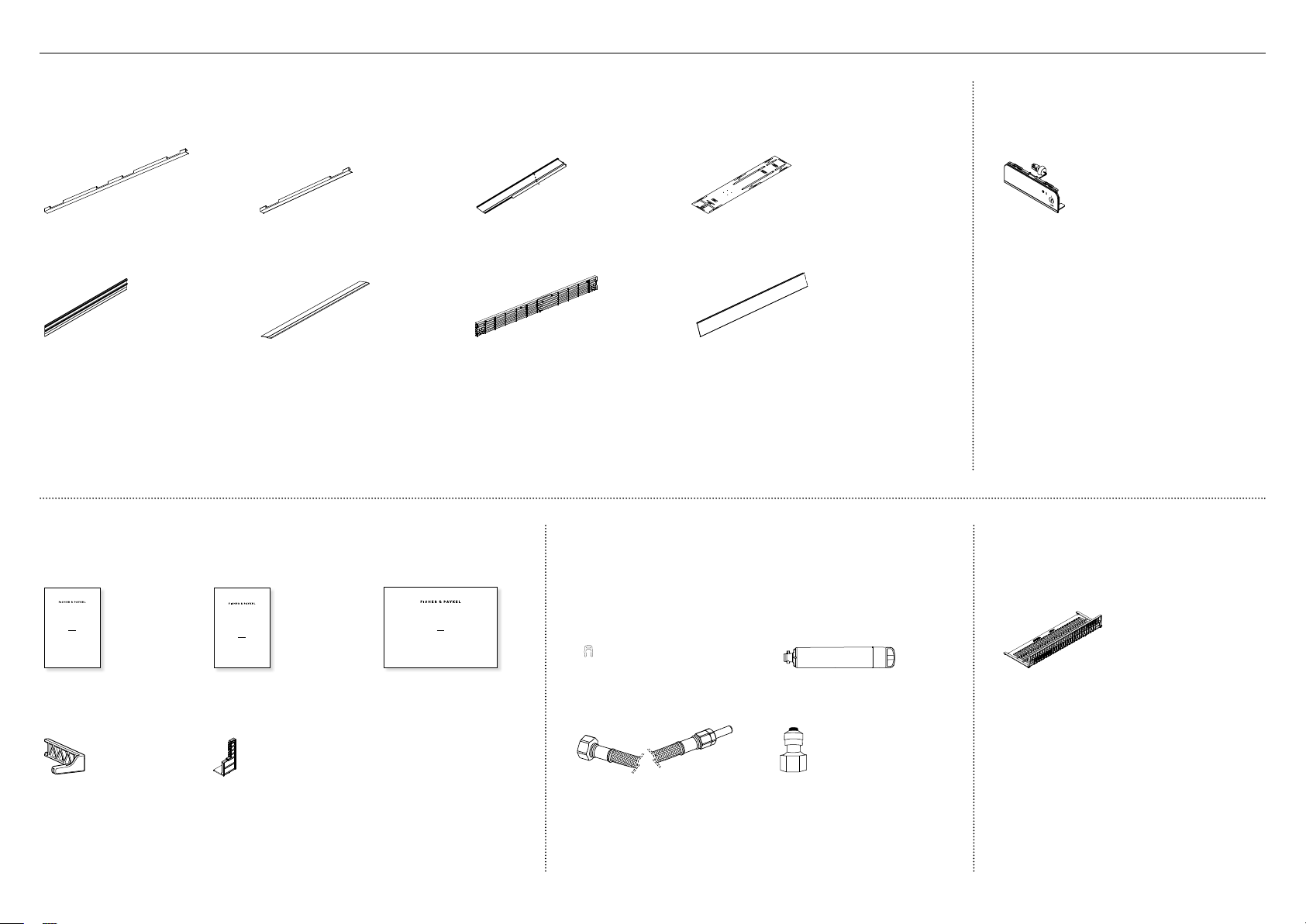
COMPONENTS
External box
Located at back panel of the appliance
Door side trim
(2)
Top trim
(1)
Drawer side trim
(2)
Drawer top trim
(1)
Miscellaneous items pack
Located inside the appliance
Cabinet side trim
(2)
Top grille
(1)
Double-sided door panel template
(1)
Toe kick
(1)
Water filter install kit
Located inside the appliance
Ice and Water display
(Ice and Water models only)
Located inside the appliance
External display module
(1)
Toe kick filter
Located inside the appliance
ACTIVESMART™
INTEGRATED REFRIGERATOR
RS90A, RS9120W,
RS36A72, RS36A80 & RS36W80 models
USER GUIDE
NZ AU GB IE HK SG IN US
User guide
(1)
Filter cartridge tool
(1)
4
SERVICE & WARRANTY
SERVICE ET GARANTIE
ΣΈΡΒΙΣ ΚΑΙ ΕΓΓΎΗΣΗ
SERVIZIO E GARANZIA
SERVICE & GARANTIE
HUOLTO JA TAKUU
SERVICE OG GARANTI
保修和维修
服務和保修
Service and Warranty
(1)
Air flow divider
(1)
ACTIVESMART™ INTEGRATED
SINGLE DOOR / DRAWER REFRIGERATOR
RS36W80 models
INSTALLATION GUIDE
US CA
844189D 02.19
Installation guide
(1)
Collet locking clip
(1)
1/4” (6mm) Stainless steel braided
hose with adaptor (1)
Water filter
(1)
Tube adaptor
(1)
Toe kick filter
(1)
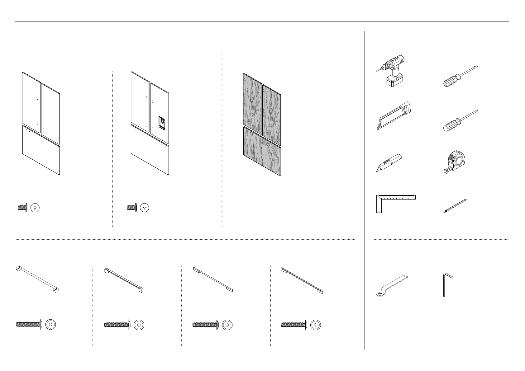
COMPONENTS TOOLS
Door panel set
Not supplied and must be purchased separately
Stainless steel (Fisher & Paykel) door panel set:
Includes 2x French door panels and 1x drawer panel.
Ice only door panel set
(RD3680 / RD3684)
Ice and Water door panel set
(RD3680U / RD3684U)
Required tools
Not included with appliance
Custom door panel set:
Supplied by customer to match their cabinetry.
Applicable for Ice only appliance models.
Powered driver Flathead screwdriver
Hacksaw Cross-head screwdriver
Cutter Measuring tape
M5x14 mush cross-head (SS) screw
(34)
M5x14 mush cross-head (SS) screw
(34)
Door handle kit
Not supplied and must be purchased separately. Select between the options below:
Professional rounded
door handle (3x)
M5x25 pan head socket
screw (12x)
Professional square
door handle (3x)
M5x25 pan head socket
screw (12x)
Contemporary round
door handle (3x)
M5x25 pan head socket
screw (12x)
Contemporary square
door handle (3x)
M5x25 pan head socket
screw (12x)
Ruler Pencil
Supplied tools
Included in internal box
FPA spanner
(1)
Hex key
(1)
5
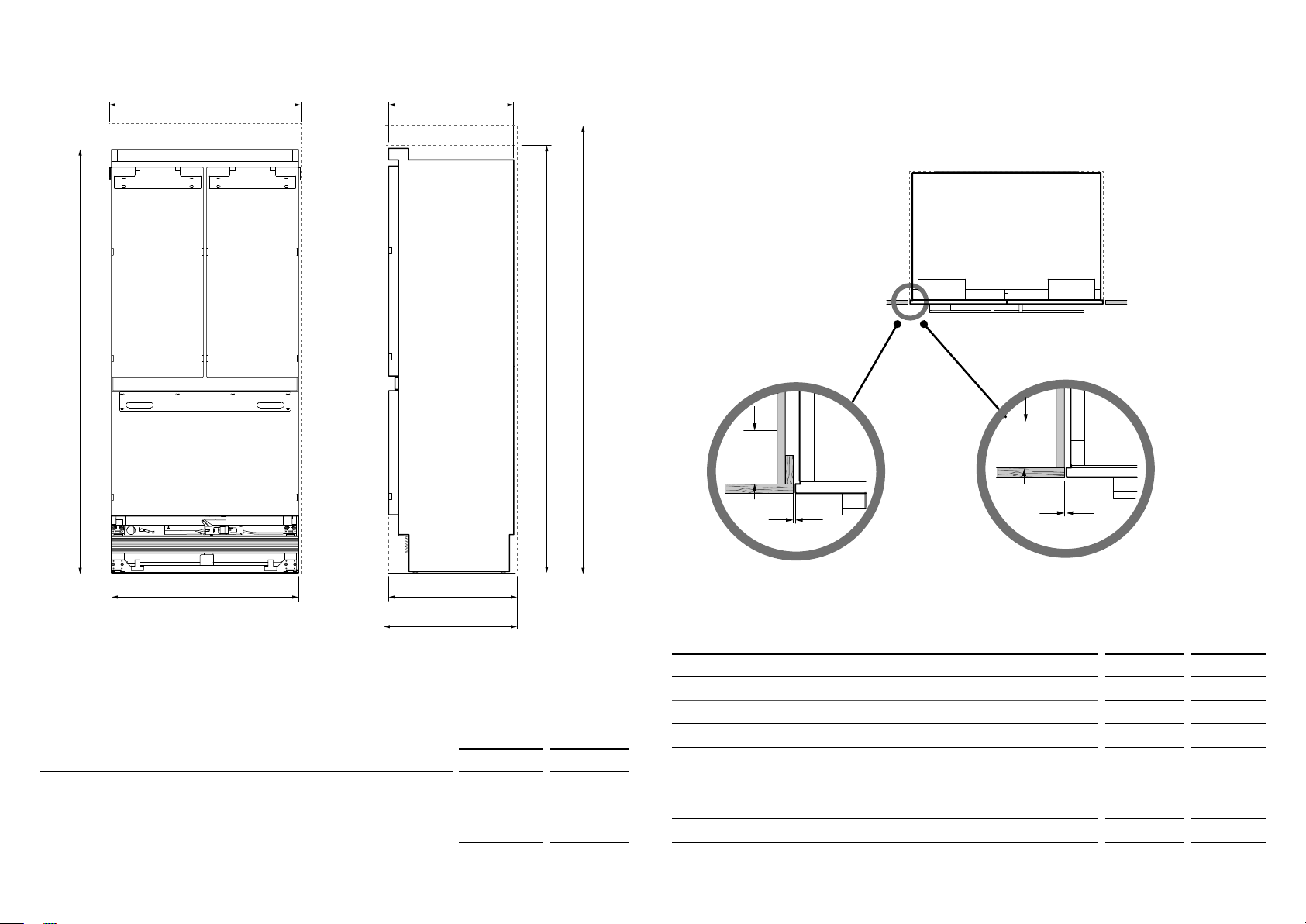
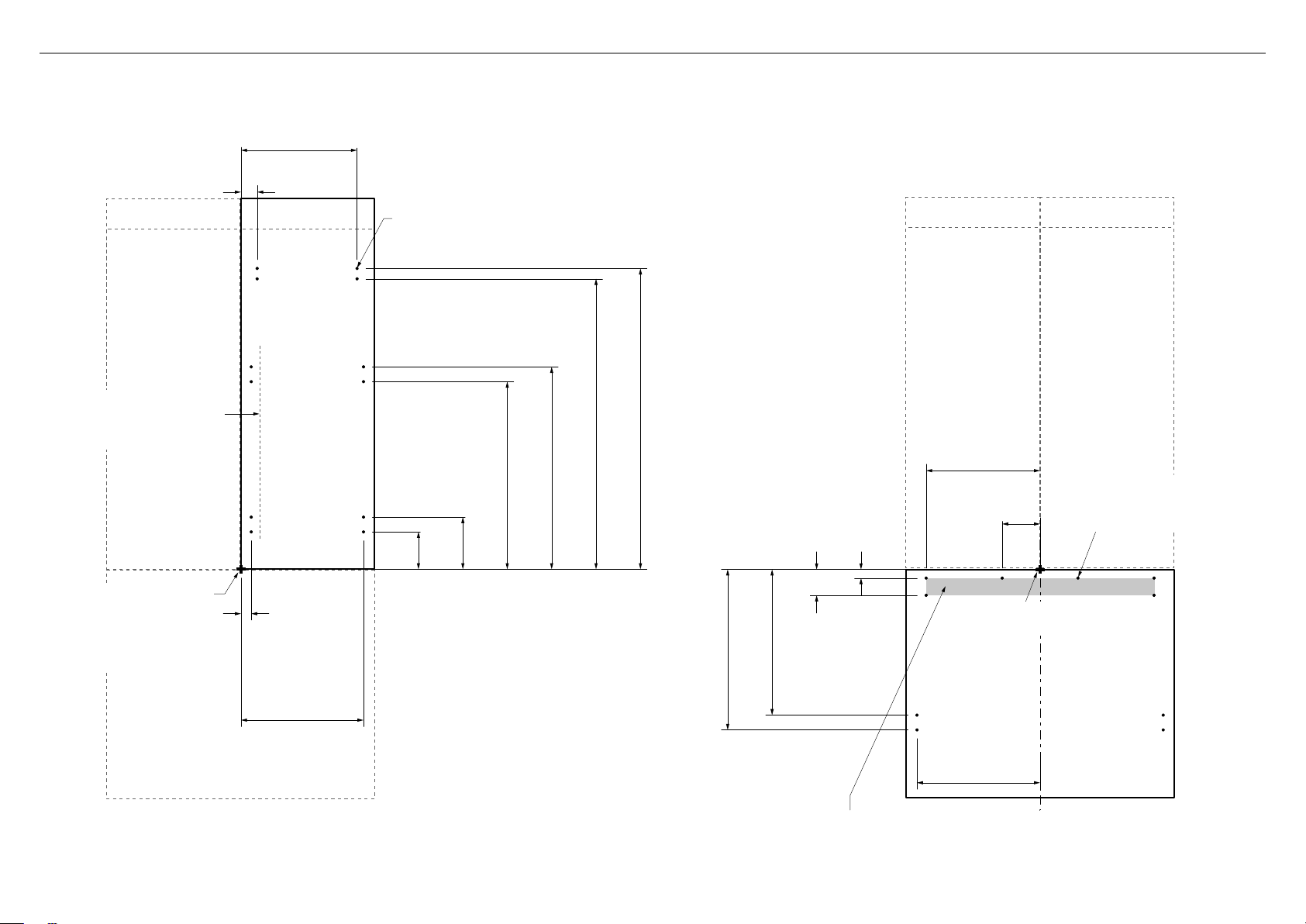
APPLIANCE AND CAVITY DIMENSIONS
g
L GF
F
g
J
I
A
f
c
d
e
IMPORTANT!
For ease of installation, ensure cavity width is consistent top
to bottom and height is consistent left to right.
PLAN VIEW
J
J
I
Flush with front
of cabinetry
I
b
FRONT VIEW SIDE VIEW
h
APPLIANCE DIMENSIONS inches mm
Overall height of appliance* 7913/16 2028
A
Overall width of appliance 3511/16 906
B
Overall depth of appliance (without door panels) 233/4 603
c
*
Includes mounted feet
6
Framed: Finished return top and sides Frameless: Finished return top and sides
CAVITY DIMENSIONS inches mm
Overall height of cavity (for appliance using RD3680 door panel set) 80 2032
D
Overall height of cavity (for appliance using RD3684 door panel set) 84 2134
e
Overall width of cavity 36 914
f
Overall depth of cavity (for flush installation) 25 635
g
Overall depth of cavity (for proud installation) 24 3/4 629
h
Minimum cabinetry gap clearance from edge of appliance 3/16 4
i
Minimum required finished return min. 31/2 89
j
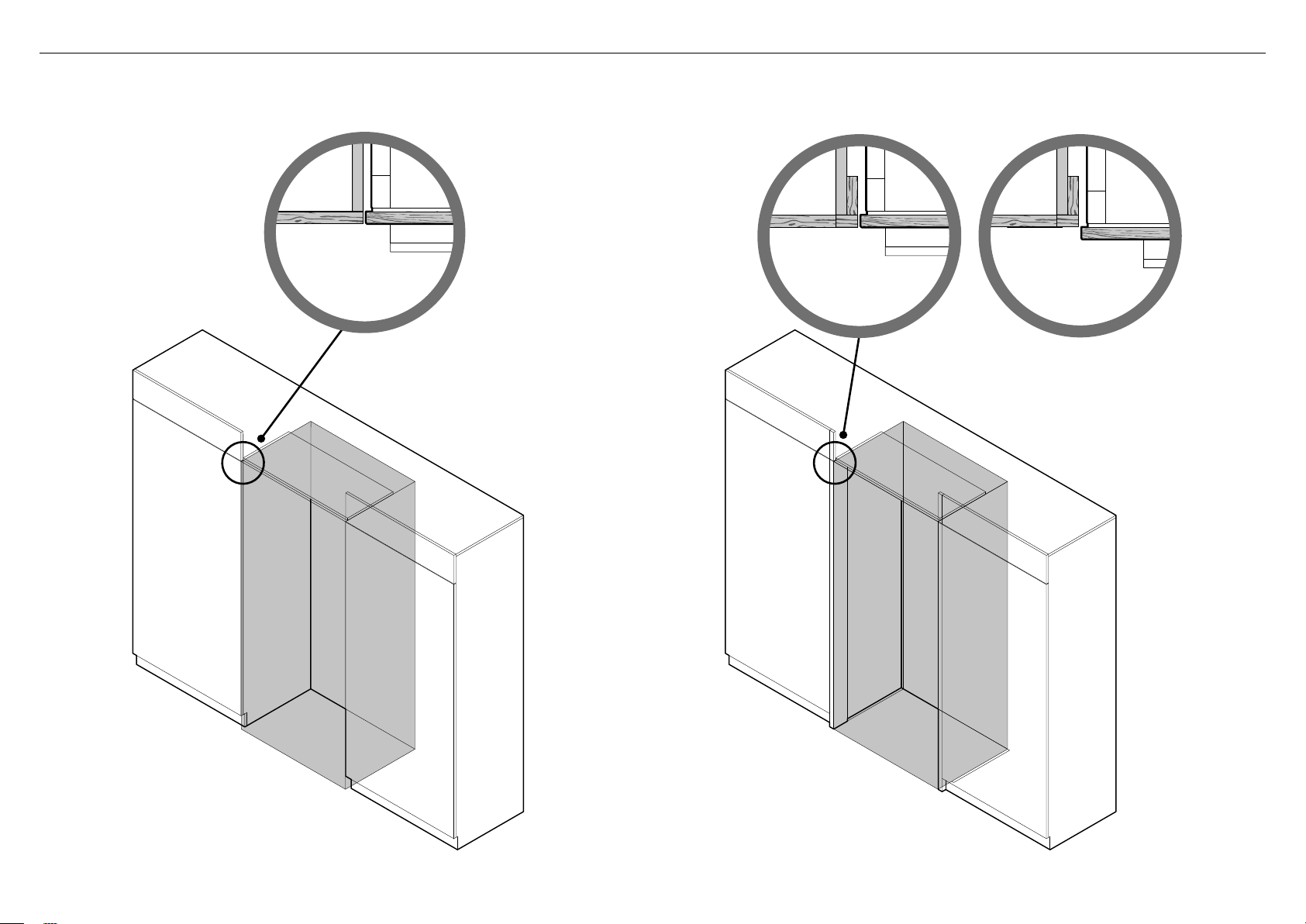
CABINETRY OPTIONS
FRAMELESS CABINETRY
(Aligns the appliance with the cabinetry)
FRAMED CABINETRY
(Aligns the appliance with the frame of the cabinetry)
Flush
installation
Proud
installation
Note: Drawings are only for reference and not the actual cavity width.
7
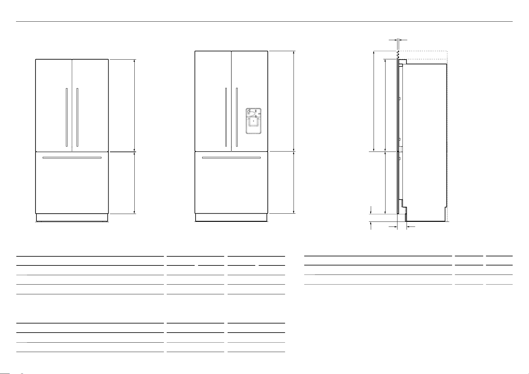
STAINLESS STEEL DOOR PANEL AND TOE KICK DIMENSIONS
a
a
c
a
b
RD3680 DOOR PANEL SET RD3684U DOOR PANEL SET
RD3680/RD3680U RD3684/RD3684U
DOOR PANEL SETS DIMENSIONS inches mm inches mm
Height of top door panels 451/4 1150 495/16 1252
a
Height of bottom drawer panel 303/8 772 303/8 772
b
Depth of appliance front panels (excluding handles) 3/4 19 3/4 19
c
Note:
●
Fisher & Paykel Stainless steel door panels are not supplied and must be purchased separately.
Model no. RD3680 / RD3684 (Iceonly model) andmodelno. RD3680U / RD3684U (Ice and Water model).
DOOR PANEL WEIGHT lbs kg
Maximum weight of each top door panel
Maximum weight of drawer panel
8
(with handle) 22 10
(with handle) 241/4 11
b
b
d
e
TOE KICK PANEL DIMENSIONS inches mm
Height of toe kick panel 4 102
d
Depth of toe kick (measured from front of door panels) 4 3/4 (120)
e
Note:
●
Stainless steel toe kick, height 4" (102mm) is supplied with the appliance.
Customers need to supply their own custom toe kick, height 4 – 6" (102 – 152mm).
●
For toe kick greater than 4, shorten the height of the bottom grille accordingly.
Refer to 'Toe kick installation' for more information.
D
g
A
E
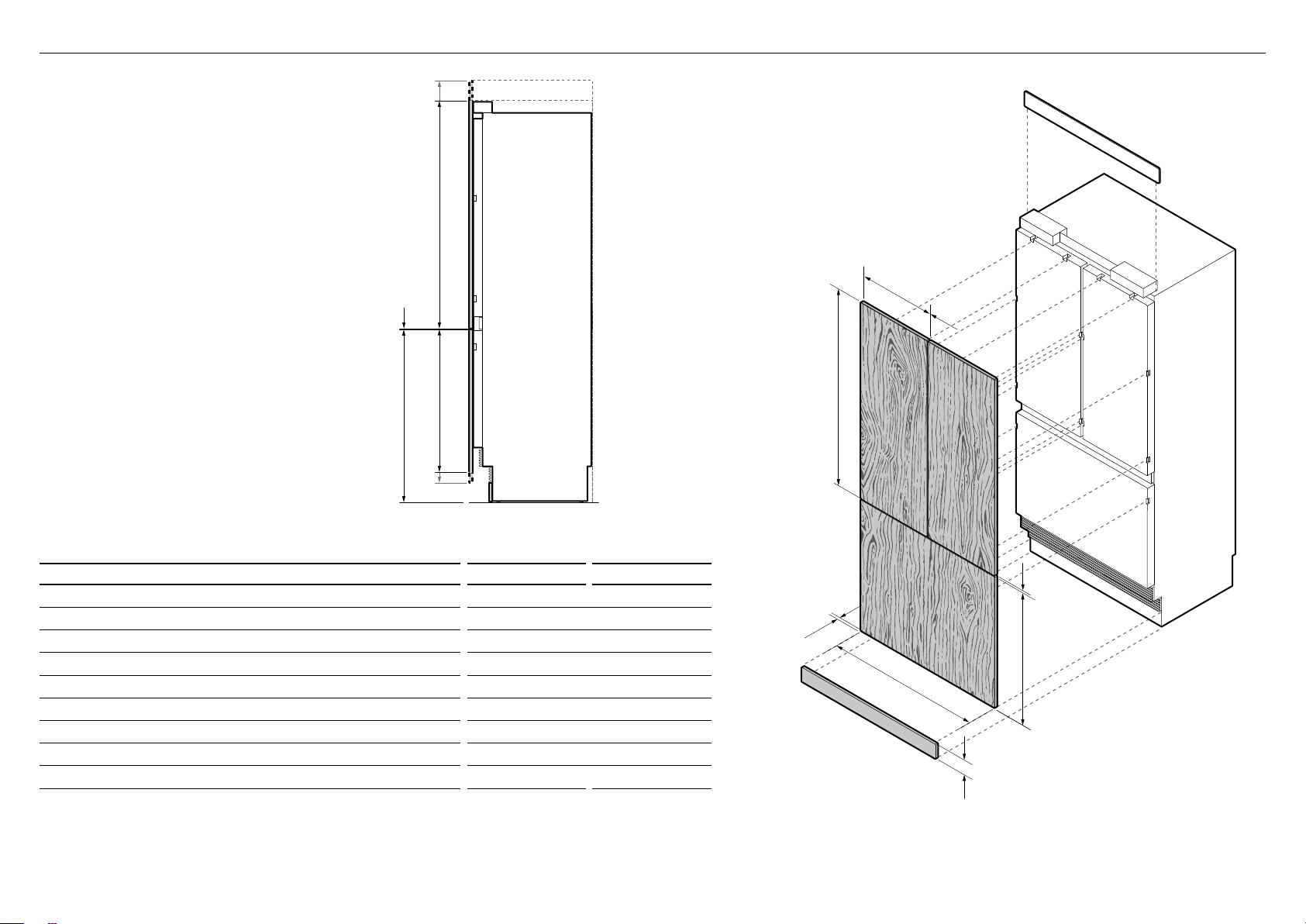
IMPORTANT!
Custom door/drawer panels are only
applicable for Ice only models.
CUSTOM DOOR PANEL AND TOE KICK DIMENSIONS
Note: Top trim supplied for
84" (2134mm) installation
A
B
g
D
E
PROFILE VIEW
DIMENSIONS inches mm
Height of top door panel 451/4 – 495/16 1150 – 1252
A
Width of top door panel 173/4 451
B
Gap between top door panels 3/16 4
C
Height of bottom drawer panel 287/16 – 303/8 722 – 772
D
Height from bottom of appliance to top of bottom drawerpanel 347/16 874
E
Width of bottom drawer panel 3511/16 906
F
Gap between top door panels and bottom drawer panel 3/16 4
G
Height of toe kick panel 4 – 6 102 – 152
H
Depth of custom door panels 5/8 – 3/4 16 – 19
I
Note:
●
Custom door panels and toe kick must be supplied by the customer.
●
Custom toe kick should be designed at 4 – 6" (102 – 152mm) relative to door / drawer panel height.
●
For toe kick greater than 4, shorten the height of the bottom grille accordingly. Refer to 'Toe kick installation' for more information.
I
A
F
C
g
D
ISO VIEW
H
9
CUSTOM DOOR PANEL INSTALLATION DIMENSIONS
The drawings below apply to Ice-only models RS36A80J. Dimensions apply for the preparation and installation of custom door panels.
For Dwg and Dxf files of the below panel preparation download the folder on thekitchentools.fisherpaykel.com.
157/16" (393mm)
23/16" (56mm)
Ø 3/32" (2mm) REF
12x Pilot holes recommended for bracket attachment.
(Do not penetrate front surface).
Ensure handle is mounted
29/16" (65mm) from inner edge
of panel to the center — this will
avoid interference with brackets.
415/16"
(126mm)
615/16"
(177mm)
2415/16" (634mm)
2615/16" (685mm)
40" (1016mm)
385/8" (982mm)
11/8"
(29mm)
153/16" (386mm)
51/16"
(129mm)
Ø 3/32" (2mm) REF
10x Pilot holes recommended
forbracket attachment.
(Do not penetrate front surface).
All measurements to be made
from inner bottom corner.
For the second panel mirror
and repeat dimensions using
inner bottom corner as the
reference point.
10
13/8" (35mm)
165/16" (415mm)
TOP PANEL—REAR VIEW
193/8" (492mm)
215/16" (542mm)
37/16"
(88mm)
Cut outs are located in attachment bracket for Fisher & Paykel handles only.
Iflocating custom handle in the shaded area above, ensure handle screw heads
are counter sunk into back of panel to avoid interference with hanging bracket.
All measurements to be made
from top and centerline.
16 3/8" (416mm)
BOTTOM PANEL—REAR VIEW
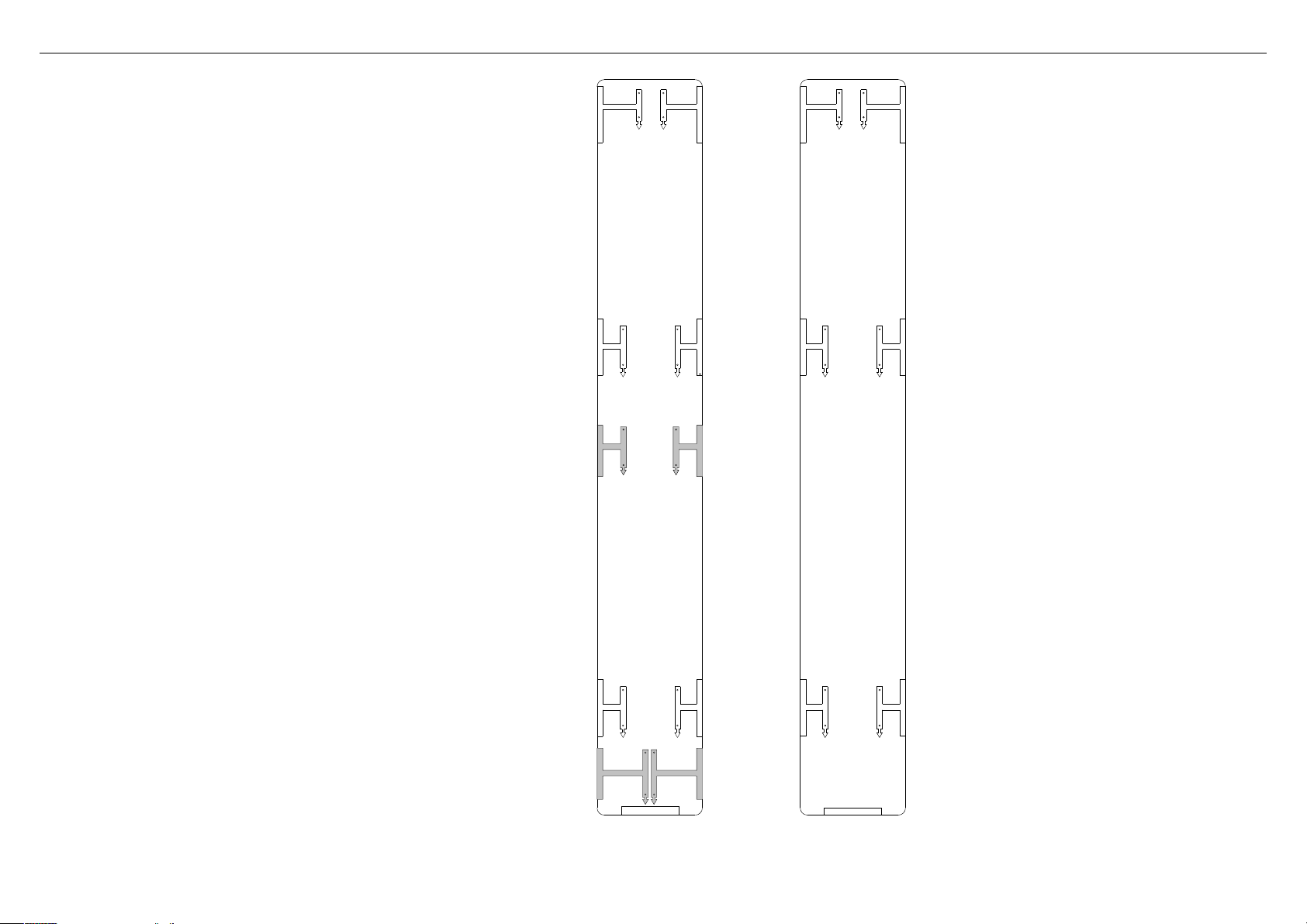
CUSTOM DOOR PANEL INSTALLATION TEMPLATE
This template is a double-sided sheet used as a guide to drill
screw holes for installing your Custom door and drawer panels.
The actual template is included with this installation guide.
Refer to 'Door panel installation — Custom' (page 32) for
moreinformation.
LEFT DOOR PANEL HINGE SIDE
HANGING BRACKET
HOLES
LEFT DOOR PANEL
AND DRAWER TEMPLATE
849551
LEFT DOOR PANEL HINGE SIDE
SIDE BRACKET HOLES
DRAWER PANEL RIGHT EDGE
SIDE BRACKET HOLES
DRAWE PANEL
FLIP FOR RIGHT
HAND DOOR PANEL
DRAWE PANEL
SIDE BRACKET HOLES
SIDE BRACKET HOLES
HOLES
HANGING BRACKET
LEFT DOOR PANEL HANDLE SIDE
LEFT DOOR PANEL HANDLE SIDE
DRAWER PANEL LEFT EDGE
RH DOOR PANEL HANDLE SIDE
HANGING BRACKET
HOLES
RIGHT DOOR
PANEL TEMPLATE
RH DOOR PANEL HANDLE SIDE
SIDE BRACKET HOLES
FLIP FOR LEFT HAND DOOR
AND DRAWER HOLES
849551
SIDE BRACKET HOLES
HOLES
HANGING BRACKET
RH DOOR PANEL HINGE SIDE
RH DOOR PANEL HINGE SIDE
LH DOOR PANEL HINGE SIDE
SIDE BRACKET HOLES
DRAWER PANEL RIGHT EDGE
LEFT PC PANEL BOTTOM EDGE
LEFT DOOR
PANEL SIDE
BRACKET HOLES
DRAWE PANEL HANGING
BRACKET HOLES
DRAWE PANEL HANGING
RH DOOR PANEL HANDLE SIDE
SIDE BRACKET HOLES
SIDE BRACKET HOLES
LH DOOR PANEL HANDLE SIDE
DRAWER PANEL LEFT EDGE
DRAWER PANEL TOP EDGE
RH DOOR PANEL BOTTOM EDGE
SIDE BRACKET HOLES
RH DOOR PANEL HINGE SIDE
RIGHT DOOR
PANEL SIDE
11
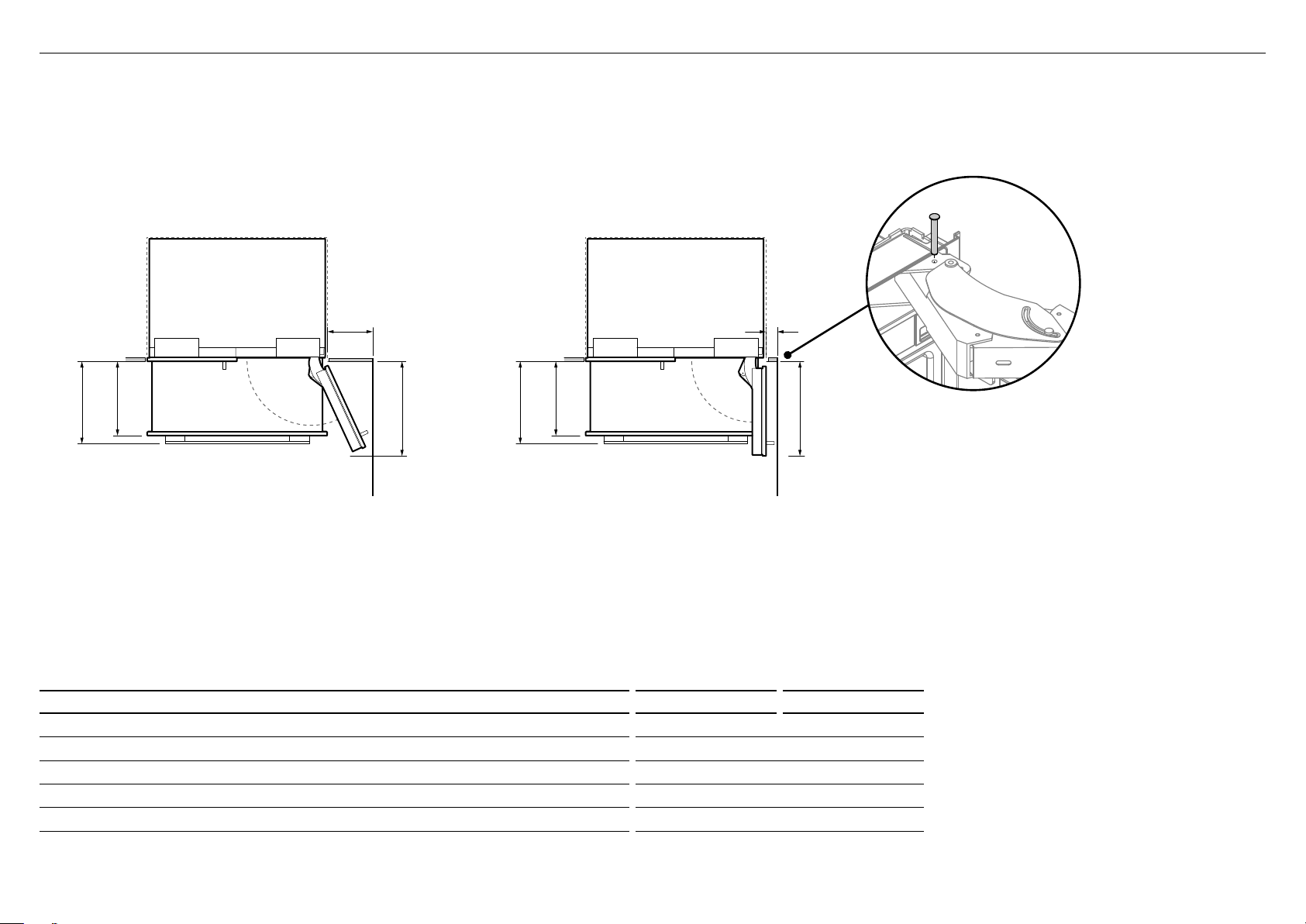
DOOR CLEARANCE
B
C
D
A
B
C
E
A
Insert hinge limiting pin
WARNING!
●
Wall Wall
(FULL INTERNAL ACCESS)
DIMENSIONS inches mm
Depth of door (widest opening) measured from front of door 187/8 480
A
Depth of drawer (open) measured from front of drawer, including handle 153/4 400
B
Depth of drawer (open) measured from front of drawer, excluding handle 143/16 360
C
Minimum door clearance* to adjacent wall (115° — full internal access) 123/8 315
D
Minimum door clearance* to adjacent wall (90° — reduced internal access) 45/16 110
E
* Measured from front cabinetry edge. An additional 3/4" (20mm) is required when using RD3680 and RD3684 door panel sets.
90° DOOR OPENING115° DOOR OPENING
Before opening the doors, ensure that the appliance is
stable.
●
Follow these steps to avoid risks that can cause serious
injury or death.
For 90° door swing, a hinge limiting pin is supplied with
yourappliance. This pin fits in the boreholes of the top hinge.
Open door to 90°.
1
Insert the hinge limiting pin vertically into the bore hole.
2
– Apply a gentle tap to the pin if it does not slide smoothly.
12

ELECTRICAL AND PLUMBING
IMPORTANT!
●
Electrical connection should be located in an adjacent cabinet to either side
oftheappliance or above the appliance cavity.
●
We recommend to use an isolating switch that is easily accessible to the user
aftertheappliance is installed.
2
1
WARNING!
●
Electrical shock hazard. Assume all parts are live.
●
Disconnect supply before servicing and installation.
Left side
of cavity
B
A
3
ELECTRICAL AND PLUMBING CONNECTIONS
Recommended location for connections in adjacent area or unit
1
Alternative location for connections above the cavity
2
Alternative location for connections at rear of cavity
3
1
Floor
D
C
Electrical and water connections must be within
this space if located behind the appliance
ELECTRICAL AND PLUMBING DIMENSIONS inches mm
Overall height of supply area 5 5/8 143
A
Overall width of supply area 29 3/4 756
B
Distance from right side of cavity 2 7/ 8 73
C
Distance from the floor 2 51
D
Note: Dimensions are based on minimum depth of cavity.
13

Maximum distance of hose and power cord
ELECTRICAL AND PLUMBING
Power cord (excl. plug)—31 1/2" (800mm)
Water inlet hose—53 1/8" (1350mm) Water inlet hose—847/16" (2120mm)
Power cord (excl. plug)—803/4" (2051mm)
ELECTRICAL SPECIFICATIONS
Supply 115VCA, 60Hz
Service 10ampères
14
RIGHT HAND SIDELEFT HAND SIDE
Power cord (excl. plug)—803/4" (2051mm)
PLUMBING SPECIFICATIONS
Supply 1/4" (6mm) comp. Stainless steel braided hose
Pressure min. 22psi (150kPa)
max. 120psi (827kPa) @ 68°F (20°C)

BEFORE INSTALLATION
IMPORTANT!IMPORTANT!
●
Be careful when unpacking to prevent damage to the surface of your appliance.
●
Ensure that the appliance is stable to prevent from tipping over when unpacking.
●
Do not open the doors to prevent the appliance from tipping over.
●
The appliance is heavy and requires a minimum of 2persons to unpack and install.
●
Ensure that the feet of the appliance are retracted.
●
If the appliance is damaged, contact your Fisher & Paykel dealer.
●
Take note of your model and registration numbers located at the lower right side of
theappliance. You will need these to request for servicing or repair of your appliance.
Checking your appliance
Remove accessories box
1
located at the back panel
ofappliance.
Refer to 'Components list' for
contents of accessories box.
IMPORTANT!
Be aware when removing the
carton that the accessories
box may have dislodged from
the rear of the appliance
during transit.
Remove the water fittings and
2
water filter kits, installation kit,
and miscellaneous items pack
from inside the appliance.
Refer to 'Components list'.
Water fittings and Water filter kits
Moving your appliance
Remove the brackets from one side of the
1
appliance. (For single door models, remove
the brackets on the non-hinged side of the
appliance).
Note: Location of brackets depends on the
model of your appliance.
Restrain the appliance
4
tothe cart with straps.
Remove the brackets
5
on the other side of
theappliance.
Tilt the appliance
2
slightly to the
opposite side.
Tilt the appliance backward
6
onto the cart.
Set aside the pallet and
7
push the cart to the
installation location.
Insert the hand truck under
3
the side of the appliance
where the brackets were
removed.
Do NOT insert the hand
truck to the front or back
oftheappliance.
hand truck
Installation kit
ACTIVESMART™
INTEGRATED REFRIGERATOR
RS90A, RS9120W,
RS36A72, RS36A80 & RS36W80 models
USER GUIDE
NZ AU GB IE HK SG IN US
Miscellaneous items pack
15

BEFORE INSTALLATION
IMPORTANT!
●
The appliance has front and rear rollers for moving the appliance forward and backward.
Do not move the appliance sideways to avoid damaging the rollers or the floor
covering/surface.
●
The appliance must be installed by a qualified installer, or Fisher & Paykel trained and
supported service technician to avoid faulty electrical connection and water leaks.
Check installation location
Check the cabinetry
1
– Check the dimensions — height, width, depth, floor level,
finishedalcovereturns.
– Ensure that the ventilation openings in the cabinetry are clear of obstruction.
– For integrated installation, a finished return of solid material is required
across the top and sides of the new or existing alcove.
– Refer to the ‘Cavity Dimensions’ table prior to installation of the appliance.
Check the power supply
2
– Ensure that there is a separate power outlet for the appliance.
– Avoid sharing the power point with other appliances to prevent the
appliancefrom accidentally switching off.
– For power requirements, refer to the information on the serial plate.
This is located at the front right-hand side of the drawer when open.
– Ensure your appliance is properly grounded (earthed).
– Connect the appliance to the electrical supply (115VAC, 60Hz) with fitted
plugand lead.
– We recommend to use an isolating switch that is easily accessible to the
userafter the appliance is installed.
– Follow the National Electrical Code and all local codes and ordinances
wheninstalling this appliance.
●
All connections for water, electrical power and grounding must comply with local codes
and ordinances and be made by licensed personnel when required.
●
Avoid installation of the appliance/s under a ground fault circuit interrupter (GFCI).
●
Ensure the appliance is installed properly. Improper installation that results in appliance
failure is not covered under the appliance warranty.
Check the water supply (for Ice and Water models only)
3
– Ensure that there is a separate water supply connection for the appliance.
– Your appliance must be installed by a qualified appliance installer as
incorrect plumbing can lead to water leaks.
– Fisher & Paykel is not liable for damage (including water damage) caused
byfaulty installation or plumbing.
16

CAVITY PREPARATION
Internal box
Anti tip
A
bracket kit
Anti-tip bracket
(1)
Masonry plug
(4)
#10x40 cross-head screw
(4)
Tools
Cross-head screwdriver
IMPORTANT!
●
The anti-tip bracket and fittings supplied must be fitted to the wall
ofthefinished enclosure to withstand 220lbs (100kg) load.
●
Ensure that anti-tip bracket is installed correctly to prevent the
appliancetipping forward when door is open.
●
Ensure the bracket is secured to structural beams or wall studs
nearesttothe center of the alcove.
Attach anti-tip bracket
Project horizontally from the bottom edge of the finished enclosure
1
towards the center of the back wall.
– For 80" (2134mm) cavity installation — measure 27/16" (62mm)
downward from the projection line (A).
– For 84" (2032mm) cavity installation — measure 67/16" (164mm)
downward from the projection line (B).
This will locate the contact surface between the bracket and appliance.
B
A
Anti-tip
bracket
WARNING!
Read the following before fastening with masonry plugs and/or screws:
●
Ensure the screws avoid electrical, gas and water conduits.
●
Ensure lightweight masonry material such as cinder block
andnewconcrete (no curing time) are not used in installation.
●
Do not use metallic materials that may corrode, stain and/or
damagetheenclosure.
C
D
E
F
Powered driver (optional)
Pencil
Mark the location for placement of the anti-tip bracket. Place the bracket
2
so the top edge of the contact surface aligns with the mark (C).
Mark the locations of the screw holes on the wall based on the most
3
central wall stud (D).
Drill screw holes to the marked locations.
4
For wooden/plaster board wall installation:
5
– Fix the bracket to the wall with #10x40 pan head cross-head screws,
and screw tightly (E).
For solid wall installation:
6
– Hammer masonry plugs into the wall until flush.
– Fix the bracket to the wall with #10x40 pan head cross-head screws
(4x), and screw tightly (F).
IMPORTANT!
When positioning the appliance
in the cabinetry, ensure that the
anti-tip bracket overlaps the
refrigerator by a minimum 2 3/8"
(60mm) for a secure hold.
.
60mm overlap
Anti-tip
bracket
If the minimum 2 3/8"
(60mm) overlap cannot
be achieved, install a
solid spacer to the wall
stud behind the bracket.
60mm overlap
Spacer
Anti-tip
bracket
17

WATER AND POWER SUPPLY CONNECTION
Water fittings kit
(Ice and Water
modelsonly)
Collet locking clip
(1)
1/4” (6mm) Stainless
steel braided hose with
adaptor (1)
IMPORTANT!
●
Ensure that the water connection is performed by a professional installer.
●
The standard appliance includes a braided water line hose compatible
withabrass adaptor.
●
Ensure there is enough tubing for the water connection and to pull
theappliance out for service, if required.
Connect to water
(for Ice and Water models only)
Move the appliance in front of the
1
cabinetry close enough toallow access
behind for power and water connections.
At the front of the appliance, insert the
2
adaptor of the braided water line hose
(A) into the PRV.
Note: If using a 1/4PEX plastic tubing,
you need to use awater fittings kit (not
supplied and must purchase separately).
Insert the tube end of the adaptor fully
3
into thePRV. Once inserted, pull gently
on the tubing to ensure it is locked in (B).
Note: Dislodge the PRV from the clips,
ifrequired.
PRV
A
braided
hose with
adaptor
B
●
Flush water through the hose prior to connection to the appliance
toremoveany debris in the hose.
●
We recommend to use an isolating switch that can be accessed
easilyafterthe appliance is installed.
F
E
18
Secure the connection by inserting a
4
lockingkey between the PRV and tube
endoftheadaptor (C).
– If the PRV is dislodged during
installation, mount the PRV back
intothe clip.
Thread the free end of the water line hose
5
intothe hole located at the base and
throughthe back of the appliance (D).
At the back of the appliance, connect the freeend
6
of the braided hose to the water supply (E), and
then loosely coil the water line hose (~2 – 3 times).
– Do not over-tighten the connection.
D
– Turn ON the water supply and check that all
connections are dry and free of drips.
C
Connect to power supply
Locate the power cord and connect the fitted
7
plug to the electrical supply (115VAC, 60Hz)(F).
Turn ON the appliance to test if working.
– If using an isolating switch, turn OFF the
appliance before continuing theinstallation.

TOP TRIM INSTALLATION
Internal box
Top trim
E
install kit
Cabinet top trim bracket
(2)
M5 nut
(6)
M5x8 cross-head screw
(12)
External box
WARNING!
●
Be careful when working with the appliance outside of the finished enclosure.
●
Ensure that the appliance is secured to prevent tipping forward. Tipping of appliance can lead to serious injury or death.
Install top trim—for 84" (2134mm cavity only)
Insert M5 nuts (A) into
1
the top and bottom
side of the left and right
ends of the top trim.
Slidethe nuts towards
the center of the trim,
~ 13" (330mm).
~ 13" (330mm)
~ 13" (330mm)
A
At the top of the
3
appliance, place the
assembled toptrim behind
the existing appliance trim.
Positionthe top trim so
that screw heads in the
appliance trim insert
through the key holes
ofthe brackets (C).
C
Top trim
(1)
Tools
Cross-head screwdriver
Powered driver (optional)
Position the top trim
2
brackets over the M5 nuts.
FastenM5x8 cross-head
screws (B) through
brackethole and secure.
~ 13" (330mm)
Slide the screws of the
4
appliance trim towards
the narrow side of
the key holes of the
brackets, and tighten
~ 13" (330mm)
the screws to lock the
top trim in position (D).
D
B
19

SIDE BRACKETS INSTALLATION
Internal box
Side bracket
F
install kit
Side base brackets
(right/left)
(2)
M5x8 countersunk
cross-head screw (4)
M5x10 cross-head screw
(10)
Tools
IMPORTANT!
●
Ensure all external packaging materials are removed from the appliance before installation.
●
Ensure the doors of the appliance are closed during installation.
Attach side base brackets
Fix the side base brackets to the base left and right sides of the appliance
1
with M5x8 countersunk cross-head screws (A).
Loosely screw (1 – 2 turns) M5x10 cross-head screws into the doors (B).
2
B
B
Cross-head screwdriver
Powered driver (optional)
20
1 – 2 turns
A
A

POSITIONING INTO CABINETRY
IMPORTANT!
●
Ensure the hose is not run over by the appliance when pushing into the cabinetry to prevent damage and possible waterleaks.
Position the appliance into the cabinetry
Coil the excess water hose and power cord flat behind the appliance (A).
1
Push the appliance into the cabinetry until the anti-tip bracket overlaps the
2
rear top edge of the appliance (B).
IMPORTANT!
●
Ensure the appliance is centered.
●
Ensure the anti-tip bracket overlaps the refrigerator by a minimum 2 3/8"
(60mm) forasecure hold (C).
2 3/8" (60mm) min.
overlap
C
Anti-tip
bracket
Refer to 'Attach anti-tip bracket' for more information.
A
21

ALIGNING INSIDE CABINETRY
Tools
Hex key
Ruler
Powered driver
IMPORTANT!
●
Ensure all four corners of the appliance is supported firmly onto the floor
toeliminate any movement.
●
DO NOT install the appliance on a soft, uneven, or unlevelled floor to avoid
twisting the appliance and poor door sealing.
●
Raise the appliance using a 7/16" (11mm) hex socket or 3/16" (4mm) hex key.
●
One turn of height adjusting nuts is equivalent to 1/16" (1mm) height adjustment.
Note: Maximum turn is 13/16" (20mm).
Align appliance inside the cabinetry
Centre the appliance within the alcove, using the adjacent
1
walls as a guide.
Turn the front and rear adjustment nuts (A) using a hex key to
2
extend the feet until it engages the floor.
– Clockwise turn raises the height and counter-clockwise
turn lowers the height.
Continue turning the adjusting screws alternately between
3
front and rear feet to align the front of the doors top to
bottom on both sides, and until you achieve the correct
alignment.
Check the top and bottom, left and right gaps by placing
4
aruler on the front of the appliance.
– Ensure the gaps between appliance and adjacent
cabinetry are even on both sides (B).
– This step will help ensure the appliance is level with the
adjacent cabinetry.
Gently push the front of the appliance to check the stability.
5
Place a ruler on the
front of the appliance to
check flushness top and
bottom, left and right.
●
If using a powered driver, use low torque setting to avoid damaging
theheight adjustment system.
●
Ensure that the top, bottom and sidge gaps are not greater than
1/16"(1.5mm) to achieve correct alignment.
●
Finalalignment will be achieved once door panels have been installed
andtheappliance is pushed back to sit flush with the cabinetry.
B
22
A A
Front roller adjustment
Rear roller adjustment

DOOR PANEL INSTALLATION - STAINLESS STEEL
Internal box
Door panel
B
attachment kit
Side bracket
(10)
Side strap
(10)
Door handle kit
M5x25 pan head socket
screw (12x)
Door panel set
M5x14 mush cross-head
(SS) screw (34)
IMPORTANT!
●
Follow these steps to avoid difficulties in door panel adjustment and cosmetic cap fitment.
●
Ensure to protect the finish of the Stainless steel door panels.
●
For non-water dispensing door panels: Leave the protective film on the panels when hanging and remove the film only when installation is complete.
Remove hanging brackets
Remove the M8 washers and M8 nuts fromthe
1
M8 studs at the top the door (A). Keep the
washers and nuts to reuse later.
Remove the hanging bracket from the top of
2
each door and set aside (B) for later installation.
A
B
Attach the door and drawer handles (C)
Remove the plastic plugs from the handle holes
3
(4 per each door panel).
Align the handle holes with the door panel
4
holes and secure with M5x25 pan head socket
screws (4 per each door panel).
Note: Door handle kit available and must be
purchased separately. Refer to 'Components'
for more details.
Attach the hanging brackets (D)
Align the bracket to the holes and secure
5
with M5x14 mush cross-head SS screws (14).
C
D
D
C
Tools
Hex key
FPA spanner
Powered driver
Attach side brackets and straps (E)
Align the brackets and straps to the holes on
6
the side of the panel and secure with M5x14
mush cross-head SS screws (20).
E
23

DOOR PANEL INSTALLATION - STAINLESS STEEL
Ice and Water display
(Ice and Water
modelsonly)
External display module
(1)
IMPORTANT!
●
Failure to follow these steps can lead to difficulties in door panel adjustment and cosmetic cap fitment.
●
For water dispensing door panels: Remove the protective film from the appliance doors before hanging door panels.
Connect the external display module (for Ice and Water models only)
Remove the external display module
1
taped to the front of the appliance.
Thread the display harness through
2
the door panel cavity (A).
– Ensure the grommet isengaged.
Turn the top display tabs at an angle
3
into the door panel (B).
– Ensure the harness is free
ofpinching.
Push firmly against the bottom
4
display tabsand insert into the door
panel until you feel itclipsecurely.
– Ensure the display is flush
withthe door panel.
A
B
Connect the display harness onto the
7
appliancedoor by inserting firmly until you
feelit clip securely (D).
– On the external display, enable the
dispenser lock to prevent any water
fromdispensing during water connection.
– To lock, press the button for
4seconds. The LED above the
buttonwillilluminate.
D
24
Remove water tube from the
5
holder on the appliance door (C).
Hang the door panel onto
6
M8studs.
– Ensure the panel is free to
pivot for water connections.
Push the water tube firmly into the spigot
8
behind the door panel until the marked line
is not visible (E).
– Ensure the water tube is routed away
from any sharp objects or corners, and
not in a location where it can be kinked
or squashed when the door panel is
secured, (as this will stop water flow).
C
E

DOOR PANEL INSTALLATION - STAINLESS STEEL
Tools
FPA spanner
Hex key
Cross-head screwdriver
Powered driver (optional)
Attach the door panels
Open the door and loosen the M5x10 cross-head screws
1
(do not remove) at the sides of the doors (A).
Hang the door panel by inserting theM8 studs
2
through the holes of the hanging bracket (B).
Slide the forks of the side brackets onto the
3
screwsof the door (C).
Screw the M8 washer and nut to each stud(D),
4
and re-tighten the side screws (E) to fix the
door panel (do not fully tighten). This will allow
opening the door without affecting adjustment
of the doorpanel.
A
E
B
D
C
25

DOOR PANEL INSTALLATION - STAINLESS STEEL
Door panel
B
attachment
kit
8x16 mush washer
(Custom) screw (2)
Tools
FPA spanner
Hex key
Cross-head screwdriver
Ruler
IMPORTANT!
●
Follow these steps to avoid difficulties in door panel adjustment and cosmetic cap fitment.
Adjust the door panels
Place a ruler on the front of the appliance to check
1
flushness top and bottom, left and right.
– Ensure the gap between the top of the door panel
and the top cabinetry is not more than 1/4" (7mm).
– To reduce this gap, raise the appliance by turning all
four adjustment nuts the same number of turns.
Each door panel has full axis adjustment to ensure
2
flushness with adjacent walls. To adjust the height of
the panel, turn the stud clockwise to raise or counterclockwise to lower the door panel (A).
Once satisfied with the alignment, secure M8 studs with
3
M8 washer and M8 nut (B). The top of the stud must
remain below the top face of the door panel.
Secure side bracket forks by
4
tightening side screws(C).
Repeat for all door panels.
Note:
– For depth adjustment,
loosen the side screws(10),
adjustthe panels and then
retightenoncesatisfied.
– Further adjustment of door
panels can be achieved by
removing door panels then
looseningthe fixing screws
for the hanging bracket and
moving the bracket sideways
to suit.
Loosen the M8 stud (D) so that
5
locking bracket can slide freely
back to front.
– Slide the locking bracket out until it touches the
back of the door panel. Fully tighten the M8 stud.
– Screw in place using a #8x16 screw through one
ofthe three slotted holes.
B
A
C
D
26

HANGING BRACKET
HOLES
HANGING BRACKET
HOLES
RH DOOR PANEL HANDLE SIDE
RH DOOR PANEL HANDLE SIDE
RIGHT DOOR
PANEL TEMPLATE
849551
RH DOOR PANEL HINGE SIDE
RH DOOR PANEL HANDLE SIDE
SIDE BRACKET HOLES
SIDE BRACKET HOLES
HANGING BRACKET
HOLES
HANGING BRACKET
HOLES
RH DOOR PANEL HANDLE SIDE
RH DOOR PANEL HANDLE SIDE
RIGHT DOOR
PANEL TEMPLATE
849551
RH DOOR PANEL HINGE SIDE
RH DOOR PANEL HANDLE SIDE
SIDE BRACKET HOLES
SIDE BRACKET HOLES
HANGING BRACKET
HOLES
HANGING BRACKET
HOLES
RH DOOR PANEL HANDLE SIDE
RH DOOR PANEL HANDLE SIDE
HANGING BRACKET
HOLES
HANGING BRACKET
HOLES
RH DOOR PANEL HANDLE SIDE
RH DOOR PANEL HANDLE SIDE
HANGING BRACKET
HOLES
RH DOOR PANEL HANDLE SIDE
RH DOOR PANEL HINGE SIDE
SIDE BRACKET HOLES
HANGING BRACKET
HOLES
RH DOOR PANEL HANDLE SIDE
FLIP FOR LEFT HAND DOOR
AND DRAWER HOLES
RH DOOR PANEL HINGE SIDE
RH DOOR PANEL HANDLE SIDE
SIDE BRACKET HOLES
SIDE BRACKET HOLES
RH DOOR PANEL BOTTOM EDGE
RIGHT DOOR
PANEL TEMPLATE
849551
RH DOOR PANEL HINGE SIDE
RH DOOR PANEL HANDLE SIDE
SIDE BRACKET HOLES
SIDE BRACKET HOLES
LEFT DOOR PANEL
AND DRAWER TEMPLATE
849551
SIDE BRACKET HOLES
SIDE BRACKET HOLES
LEFT DOOR PANEL HINGE SIDE
LEFT DOOR PANEL HANDLE SIDE
FLIP FOR RIGHT
HAND DOOR PANEL
LH DOOR PANEL HANDLE SIDE
LH DOOR PANEL HINGE SIDE
SIDE BRACKET HOLES
SIDE BRACKET HOLES
DRAWER PANEL LEFT EDGE
DRAWER PANEL RIGHT EDGE
DRAWE PANEL
SIDE BRACKET HOLES
DRAWE PANEL
SIDE BRACKET HOLES
DRAWER PANEL LEFT EDGE
DRAWER PANEL RIGHT EDGE
DRAWE PANEL HANGING
BRACKET HOLES
DRAWE PANEL HANGING
BRACKET HOLES
LEFT PC PANEL BOTTOM EDGE
DRAWER PANEL TOP EDGE
External box
Door panel double-sided
template (1)
Tools
DOOR PANEL INSTALLATION - CUSTOM
IMPORTANT!
●
The template is a single sheet with one side used for the left door panel/
drawer panel and the other side for the right door panel.
●
The template should be placed on the back side of the door panel.
●
Sample image below shows template applied to door panel RD3680.
Using the installation template
(for left French door panel)
back side of
door panel
front side of
door panel
Cross-head screwdriver
Powered driver (optional)
2 Mark drill locations of
screw holes for the left
hanging bracket and side
brackets. Drillscrew 3/32"
(2mm) holes to the marked
locations.
1A Align left side edge of
template with left side
edge of top door panel.
1
RH DOOR PANEL HINGE SIDE
HANGING BRACKET
RH DOOR PANEL HANDLE SIDE
RH DOOR PANEL HANDLE SIDE
HOLES
RIGHT DOOR
PANEL TEMPLATE
849551
SIDE BRACKET HOLES
FLIP FOR LEFT HAND DOOR
AND DRAWER HOLES
SIDE BRACKET HOLES
SIDE BRACKET HOLES
SIDE BRACKET HOLES
HOLES
HANGING BRACKET
RH DOOR PANEL HINGE SIDE
RH DOOR PANEL HINGE SIDE
RH DOOR PANEL HANDLE SIDE
HANGING BRACKET
HOLES
PANEL TEMPLATE
RH DOOR PANEL HANDLE SIDE
FLIP FOR LEFT HAND DOOR
RIGHT DOOR
849551
SIDE BRACKET HOLES
AND DRAWER HOLES
SIDE BRACKET HOLES
HOLES
HANGING BRACKET
RH DOOR PANEL HINGE SIDE
4 Mark drill locations of screw
holes for the right hanging
bracket and side brackets.
RH DOOR PANEL HINGE SIDE
Drill 3/32" (2mm) screw holes
to the markedlocations.
5A Align right side edge of
template with right side
edge of top door panel.
RH DOOR PANEL HANDLE SIDE
SIDE BRACKET HOLES
SIDE BRACKET HOLES
RH DOOR PANEL HINGE SIDE
RH DOOR PANEL HINGE SIDE
1B Align bottom of template with
bottom edge of top door panel.
RH DOOR PANEL BOTTOM EDGE
3 Move the same template to
right hand side of door panel.
RH DOOR PANEL BOTTOM EDGE
5B Align bottom of template with
bottom edge of top door panel.
27

RH DOOR PANEL HINGE SIDE
RH DOOR PANEL HINGE SIDE
RH DOOR PANEL HINGE SIDE
HANGING BRACKET
HOLES
HANGING BRACKET
HOLES
RH DOOR PANEL HANDLE SIDE
RH DOOR PANEL HINGE SIDE
RIGHT DOOR
PANEL TEMPLATE
849551
RH DOOR PANEL HINGE SIDE
RH DOOR PANEL HANDLE SIDE
SIDE BRACKET HOLES
SIDE BRACKET HOLES
HANGING BRACKET
HOLES
RH DOOR PANEL HINGE SIDE
RH DOOR PANEL HINGE SIDE
SIDE BRACKET HOLES
HANGING BRACKET
HOLES
RH DOOR PANEL HINGE SIDE
FLIP FOR LEFT HAND DOOR
AND DRAWER HOLES
RH DOOR PANEL HINGE SIDE
RH DOOR PANEL HANDLE SIDE
SIDE BRACKET HOLES
SIDE BRACKET HOLES
RH DOOR PANEL BOTTOM EDGE
RH DOOR PANEL HINGE SIDE
SIDE BRACKET HOLES
RH DOOR PANEL HINGE SIDE
SIDE BRACKET HOLES
RH DOOR PANEL HINGE SIDE
SIDE BRACKET HOLES
HANGING BRACKET
HOLES
HANGING BRACKET
HOLES
RH DOOR PANEL HANDLE SIDE
RH DOOR PANEL HINGE SIDE
HANGING BRACKET
HOLES
HANGING BRACKET
HOLES
RH DOOR PANEL HINGE SIDE
RH DOOR PANEL HINGE SIDE
IMPORTANT!
●
Flip the template over to use for the right top door panel.
●
The template should be placed on the back side of the door panel.
Using the installation template
(for right French door panel)
DOOR PANEL INSTALLATION - CUSTOM
back side of
door panel
front side of
door panel
Mark drill locations of
2
screw holes for the left
hanging bracket and side
brackets. Drill 3/32" (2mm)
screw holes to the marked
locations.
Align left side edge of
1A
template with left side
edge of top door panel.
RH DOOR PANEL HINGE SIDE
HANGING BRACKET
HOLES
HOLES
HANGING BRACKET
RH DOOR PANEL HINGE SIDE
RH DOOR PANEL HANDLE SIDE
HANGING BRACKET
HOLES
HOLES
HANGING BRACKET
4 Mark drill locations of screw
holes for the right hanging
bracket and side brackets.
RIGHT DOOR
PANEL TEMPLATE
RH DOOR PANEL HANDLE SIDE
SIDE BRACKET HOLES
FLIP FOR LEFT HAND DOOR
AND DRAWER HOLES
849551
SIDE BRACKET HOLES
RH DOOR PANEL HINGE SIDE
RIGHT DOOR
PANEL TEMPLATE
RH DOOR PANEL HANDLE SIDE
SIDE BRACKET HOLES
FLIP FOR LEFT HAND DOOR
AND DRAWER HOLES
849551
SIDE BRACKET HOLES
Drill 3/32" (2mm) screw holes
to the marked locations.
5A Align right side edge of
template with right side
edge of top door panel.
1
RH DOOR PANEL HANDLE SIDE
SIDE BRACKET HOLES
SIDE BRACKET HOLES
RH DOOR PANEL HINGE SIDE
RH DOOR PANEL HANDLE SIDE
SIDE BRACKET HOLES
SIDE BRACKET HOLES
28
1B Align bottom of template with
bottom edge of top door panel.
RH DOOR PANEL BOTTOM EDGE
3 Move the same template to
right hand side of door panel.
RH DOOR PANEL BOTTOM EDGE
5B Align bottom of template with
bottom edge of top door panel.

FLIP FOR RIGHT
HAND DOOR PANEL
LH DOOR PANEL HANDLE SIDE
LH DOOR PANEL HINGE SIDE
SIDE BRACKET HOLES
SIDE BRACKET HOLES
DRAWER PANEL LEFT EDGE
DRAWER PANEL RIGHT EDGE
DRAWE PANEL
SIDE BRACKET HOLES
DRAWE PANEL
SIDE BRACKET HOLES
DRAWER PANEL RIGHT EDGE
DRAWE PANEL HANGING
BRACKET HOLES
BRACKET HOLES
DRWN DAT E CHKD ECN REV
BJ 04/04/19 1
1
862947
GRAPHICS RS36A DOOR TEMPLATETITLE:
DRAWN: DATE:
SCALE: 1:1
FISHER & PAYKEL APPLIANCES LIMITED
GRAPHICS NO:
REVISION:
BINIL JOSE
04/04/2019
400mm
LEFT DOOR PANEL HANDLE SIDE
LEFT DOOR PANEL HANDLE SIDE
LH DOOR PANEL HANDLE SIDE
DRAWER PANEL LEFT EDGE
DRAWER PANEL LEFT EDGE
FLIP FOR RIGHT
HAND DOOR PANEL
LH DOOR PANEL HINGE SIDE
SIDE BRACKET HOLES
DRAWER PANEL RIGHT EDGE
DRAWE PANEL
SIDE BRACKET HOLES
DRAWER PANEL RIGHT EDGE
DRWN DAT E CHKD ECN REV
BJ 04/04/19 1
1
862947
GRAPHICS RS36A DOOR TEMPLATETITLE:
DRAWN: DATE:
SCALE: 1:1
FISHER & PAYKEL APPLIANCES LIMITED
GRAPHICS NO:
REVISION:
BINIL JOSE
04/04/2019
400mm
LH DOOR PANEL HANDLE SIDE
DRAWER PANEL LEFT EDGE
DRAWER PANEL RIGHT EDGE
DRAWE PANEL HANGING
BRACKET HOLES
DRAWE PANEL HANGING
BRACKET HOLES
LEFT PC PANEL BOTTOM EDGE
DRAWER PANEL TOP EDGE
1
DRAWER PANEL RIGHT EDGE
DRAWE PANEL HANGING
BRACKET HOLES
DRAWE PANEL HANGING
BRACKET HOLES
LEFT PC PANEL BOTTOM EDGE
DRAWER PANEL TOP EDGE
1
IMPORTANT!
●
Use left door panel template to use for the drawer panel.
●
Place the template at the back side of the drawer panel.
1A Align top of template with
top edge of drawerpanel.
1B Align left side edge of
template with left side edge
of drawer panel.
2 Mark drill locations of
screw holes for the left
hanging bracket and side
brackets. Drill 3/32" (2mm)
screw holes to the marked
locations.
Using the installation template
(for drawer panel)
DOOR PANEL INSTALLATION - CUSTOM
DRAWER PANEL TOP EDGE
SIDE BRACKET HOLES
SIDE BRACKET HOLES
DRAWE PANEL
back side of
6 To mark the drill locations of middle
screw holes, align the screw holes of
drawer panel
the drawer hanging bracket with the
right and left drilled screw holes. Drill
screw holes to the marked locations.
LEFT PC PANEL BOTTOM EDGE
DRAWE PANEL HANGING
BRACKET HOLES
BRACKET HOLES
DRAWE PANEL HANGING
DRAWER PANEL RIGHT EDGE
SIDE BRACKET HOLES
LH DOOR PANEL HINGE SIDE
HAND DOOR PANEL
FLIP FOR RIGHT
DRAWE PANEL
SIDE BRACKET HOLES
DRAWER PANEL RIGHT EDGE
DRAWER PANEL LEFT EDGE
LH DOOR PANEL HANDLE SIDE
DRAWER PANEL LEFT EDGE
front side of
door panel
DRAWER PANEL TOP EDGE
DRAWE PANEL HANGING
BRACKET HOLES
BRACKET HOLES
DRAWE PANEL HANGING
SIDE BRACKET HOLES
SIDE BRACKET HOLES
DRAWE PANEL
LEFT PC PANEL BOTTOM EDGE
DRAWER PANEL RIGHT EDGE
SIDE BRACKET HOLES
LH DOOR PANEL HINGE SIDE
HAND DOOR PANEL
FLIP FOR RIGHT
DRAWE PANEL
SIDE BRACKET HOLES
DRAWER PANEL RIGHT EDGE
4A Align top of template with
top edge of drawer panel.
4B Align right side edge of
template with right side
edge of drawerpanel.
5 Mark drill locations of
screw holes for the left
hanging bracket and side
brackets. Drill 3/32" (2mm)
screw holes to the marked
locations.
HANGING BRACKET
SIDE BRACKET HOLES
SIDE BRACKET HOLES
LEFT DOOR PANEL HINGE SIDE
849551
AND DRAWER TEMPLATE
LEFT DOOR PANEL
HOLES
HOLES
HANGING BRACKET
3 Move the same template to
LEFT DOOR PANEL HINGE SIDE
right hand side of drawer panel.
LEFT DOOR PANEL HANDLE SIDE
SIDE BRACKET HOLES
SIDE BRACKET HOLES
LEFT DOOR PANEL HINGE SIDE
849551
AND DRAWER TEMPLATE
LEFT DOOR PANEL HANDLE SIDE
HANGING BRACKET
LEFT DOOR PANEL
HOLES
HOLES
HANGING BRACKET
LEFT DOOR PANEL HINGE SIDE
29

DOOR PANEL INSTALLATION CUSTOM
Internal box
Door panel
B
attachment kit
Side bracket
(10)
Side strap
(10)
#8x16 mush washer
(Custom) screw (36)
Door handle kit
M5x25 pan head socket
screw (12x)
Remove hanging brackets
Remove the M8 washers and M8 nuts
1
fromtheM8 studs at the top the door (A).
Keepthe washers and nuts to reuse later.
Remove the hanging bracket from the top of
2
each door and set aside (B) for later installation.
A
B
Attach the door and drawer handles (C)
Align the handle holes with the door panel
3
holes and secure with M5x25 pan head
socket screws (4 per each doorpanel).
Note: Door handle kit available and
must be purchased separately.
Refer to 'Components' for moredetails.
Attach the hanging brackets (D)
Align the bracket to the holes
4
and secure with #8x16 mush
washer screw (14).
C
C
D
D
Tools
Hex key
FPA spanner
Powered driver (optional)
30
Attach side brackets and straps (E)
Align the brackets and straps to the holes
5
on the side of the panel and secure with
#8x16 mush washer screw (20).
E

DOOR PANEL INSTALLATION - CUSTOM
Tools
FPA spanner
Hex key
Cross-head screwdriver
Powered driver
(optional)
Attach the door panels
Open the door and loosen the M5x10 cross-head
1
screws (do not remove) at the sides of the doors (A).
Hang the door panel by inserting the M8 studs
2
through the holes of the hanging bracket (B).
Slide the forks of the side brackets onto the
3
screwsof the door (C).
Screw the M8 washer and nut to each stud(D),
4
and re-tighten the side screws (E) to fix the
door panel (do not fully tighten). This will allow
opening the door without affecting adjustment
of the door panel.
E
A
B
D
C
31

DOOR PANEL INSTALLATION - CUSTOM
Door panel
B
attachment
kit
8x16 mush washer
(Custom) screw (2)
Tools
FPA spanner
Hex key
Cross-head screwdriver
Ruler
IMPORTANT!
●
Follow these steps to avoid difficulties in door panel adjustment and cosmetic cap fitment.
Adjust the door panels
Place a ruler on the front of the appliance to check
1
flushness top and bottom, left and right.
– Ensure the gap between the top of the door panel
and the top cabinetry is not more than 1/4" (7mm).
– To reduce this gap, raise the appliance by turning all
four adjustment nuts the same number of turns.
Each door panel has full axis adjustment to ensure
2
flushness with adjacent walls. To adjust the height of
the panel, turn the stud clockwise to raise or counterclockwise to lower the door panel (A).
Once satisfied with the alignment, secure M8 studs with
3
M8 washer and M8 nut (B). The top of the stud must
remain below the top face of the door panel.
Secure side bracket forks by
4
tightening side screws(C).
Repeat for all door panels.
Note:
– For depth adjustment,
loosen the side screws(10),
adjustthe panels and then
retightenoncesatisfied.
– Further adjustment of door
panels can be achieved by
removing door panels then
looseningthe fixing screws
for the hanging bracket and
moving the bracket sideways
to suit.
Loosen the M8 stud (D) so that
5
locking bracket can slide freely
back to front.
– Slide the locking bracket out until it touches the
back of the door panel. Fully tighten the M8 stud.
– Screw in place using a #8x16 screw through one
ofthe three slotted holes.
B
A
C
D
32

FIXING TO CABINETRY
Internal box
Fixing bracket
G
install kit
Fixing bracket
(4)
M5x8 countersunk
cross-head screw (12)
Screw cover
(4)
#8x19 twin thread screw
(8)
Attach fixing brackets
A
Open the refrigerator French doors carefully.
1
Place the fixing brackets on the top and side base brackets of the
2
appliance and secure mid-way with M5x8 countersunk cross-head screws
(A).
B
Secure the center of each fixing bracket to the side of the adjacent wall
3
with #8x19 twin thread screws (B).
Tools
Cross-head screwdriver
Powered driver (optional)
Slide the screw cover between the fixingbracket
4
and the side bracket on the appliance (C).
C
D
Fix the screw cover by tightening M5x8 countersunk
5
cross-head screws (D).
33

WATER FILTER INSTALLATION
Miscellaneous
itemspack
Water filter
(1)
Filter cartridge tool
(1)
IMPORTANT!
●
The water filter head must be firmly pushed into the appliance and secured. incorrect installation can lead to water leaks.
Filter
A
handle
Front view
Filter in locked position
Install the water filter
Remove the plastic wrapping of the new filter.
1
Pull the freezer drawer out slightly and insert the filter into the casing
2
at the bottom left corner of the appliance. Ensurethe filter handle is
positioned vertically (A).
Push the cartridge firmly inside the casing all the way intothe filter head.
3
Align the filter removal tool over the filter handle and turn 90° clockwise
4
to tighten (B). Remove filter removal tool and close the freezer drawer.
IMPORTANT!
●
Before turning on your automatic ice maker, the water filter must
be flushed to remove any impurities or trappedair in thewater tank
andfilter system.
●
Refer to the user guide ‘Operating instructions —Automatic ice maker’
for more information.
B
34

External box
Toe kick filter
(1)
TOE KICK INSTALLATION
C
Top grille
(1)
A
Install the toe kick filter
Fit the filter onto the rails and push until it clips securely (A).
1
B
Install the top grille
Alignthe top grille clips to the top plinth slots. Ensure the top grille is
2
in the correct orientation (B).
Push the grille firmly onto the appliance until the clips engage (C).
3
35

DETAIL A
SCALE 1 : 1
IF TOEKICK IS HIGHER THAN 4" USE SIDE CUTTER TO
1.
CUT UNREQUIRED VANES FROM DOTTOM
DRILL HOLES THROUGH DIMPLES
2.
USE PROVIDED SCREWS TO FIX GRILL TO
3.
MATCHING HOLES ON PLASTIC PARTS
DETAIL A
SCALE 1 : 1
DETAIL A
SCALE 1 : 1
IF TOEKICK IS HIGHER THAN 4" USE SIDE CUTTER TO
1.
CUT UNREQUIRED VANES FROM DOTTOM
DRILL HOLES THROUGH DIMPLES
2.
USE PROVIDED SCREWS TO FIX GRILL TO
3.
MATCHING HOLES ON PLASTIC PARTS
DETAIL A
SCALE 1 : 1
DETAIL A
SCALE 1 : 1
DETAIL A
SCALE 1 : 1
TOE KICK INSTALLATION
Internal box
Door/drawer
E
trim install kit
Dual adhesive tabs
(2)
Miscellaneous
Z
components
#8x16 panhead screw (3)
Miscellaneous
itemspack
Air flow divider
(1)
External box
Toe kick
(1)
Tools
IMPORTANT!
●
The standard appliance includes a stainless steel toe kick 4 (102mm) and the components required to mount the toe kick.
●
Alternatively, the customer can supply their own custom toe kick 4–6 (102–152mm) for complete integration of the appliance.
For standard toe kick — 4" (102mm)
Loosen the toe kick bracket screws (A) mid-way, and move
1
the brackets forward (B).
A
For custom toe kick greater than 4" (102mm)
Remove the bottom grille from the bottom of the appliance.
5
Measure the required height for the bottom grille.
6
On a board, carefully score / cut theexcess vanes from
thebottom of the toe kick grille and discard (E).
Drill Ø 5/32 (4mm) holes into the dimples of the grille (F).
7
B
Pre-align the toe kick by placing in front of the brackets until flush
2
with surrounding cabinetry. Once satisfied with the alignment,
set the toe kick aside and tighten the bracket screws to lock the
brackets in position.
Peel off the adhesive backing from one side of dual adhesive tabs
3
and attach to the brackets. Peel off the adhesive backing from the
other side of dual adhesive tabs and attach the toe kick (C).
With the grille tabs facing upwards, align the grille to
8
the bottom of the plinth where the screw holes are
located and secure with #8x16 pan head screws (G).
Cut excess vanes from the bottom of the grille
C
F
E
Grille tabs
G
Front right view
Cutter
Cross-head screwdriver
36
Align the air flow divider underneath the grille tabs indicator
4
and clip onto the vanes of the bottom grille (D).
Align the air flow divider underneath the grille tabs
9
indicator and clip onto the vanes of the bottom grille (H).
H
D

DOOR AND DOOR TRIMS INSTALLATION
Internal box
Door/drawer
C
trim install kit
Dual adhesive tabs
(10)
Side cover
(4)
Top cover
(2)
External box
Door side trim
(2)
Drawer side trim
(2)
Attach the covers
If applicable, remove any remaining protective
1
film on your door panels.
Open both doors. Attach the top covers (A)
2
firmly over the top studs, and the side covers
(B) to the side brackets.
A
B
Attach the door side trims
Install the side trims by inserting into the panel gaps on each side of the
3
door(s) (C). Align the trim to the top of the door and press evenly into the
panel gap until fully seated (D).
Attach the drawer top and side trims
Peel off two dual adhesive tabs and press them
4
together to form a pair (E). Remove the adhesive
backing on one side only.
Press firmly to the underside of the drawer top trim
5
inthe indicated locations (F).
E
Remove the remaining adhesive backing from thedual adhesive tabs.
4
Locate the trim against the back surface of the panel and press down
5
firmly. Ensure the trim is fully seated against the drawer surface (G).
Install the side trims by inserting into the panel gaps on each side of the
6
door(s) (H).
– Make sure the cabinet is centered to prevent the side trims from
interfering with the cabinet.
F
Drawer top trim
(1)
G
C
D
H
37

0
TWO METHODS ARE AVAILABLE FOR ATTACHING CABINET SIDE TRIMS:
[A] FLEXIBLE SPRING CLIP METHOD — RECOMMENDED METHOD
[B] FIXED SCREW METHOD — METHOD TO USE IF CABINET IS NOT TO SPECIFICATION
(Attempt method [A]. If method [A] results in poor fitment of side trims due to cabinetry that is uneven or out of specification, use method [B]).
CABINET TRIMS INSTALLATION—[A] FLEXIBLE SPRING CLIP METHOD
Internal box
Cabinet side
D
trim install kit
Side trim bracket
(6)
Spring clip
(6)
External box
Cabinet side trim
(2)
Tools
Break off the datum lip to each side trim bracket and discard.
1
Repeat for all side trim brackets.
Discard
A
Aluminum
For 80 (2032mm) cavity installation only
Measure 4" (102mm) from the top of
2
theside trim with a square ruler and mark
acutting line (A).
Cut along the line using a fine tooth
3
hacksaw to a length of 76" (1930mm) (B).
Place 3 side trim brackets onto
4
eachside trim.
Note: Measure from the top of the
trim, with the short lip at the bottom.
Refer to (B) for 80" and 84" bracket
locations and trim orientation.
80 = 9" (229mm)
84 = 13" (330mm)
IMPORTANT!
Each bracket has two engagement
points for the side trim to locate.
Ensure the trim is engaged in both
points (C).
Repeat for all side trims.
80 = 36" (914mm)
84 = 40" (1016mm)
B
Plastic
Side trim
bracket
80 = 65" (1651mm)
84 = 69" (1753mm)
Hacksaw
Pencil
38
IMPORTANT!
●
Ensure the cut is straight and square
asthis is an exposed surface.
●
Ensure the plastic part does not bend
asthis can causevisual stressmarks.
Repeat for all sidetrims.
short lip
Side trim
Top view of side trim engaged
correctly in side trim bracket
short lip
C
B

CABINET TRIMS INSTALLATION—[A] FLEXIBLE SPRING CLIP METHOD
Insert the spring clip into the gap between the side trim and side trim bracket,
5
orientation as shown in figures (D) and (E).
IMPORTANT!
Ensure spring clip is correctly oriented with the open loop facing the side
trimlip.
Repeat for all side trims.
Spring clip
Side trim lip
Open the French doors. Place the assembled side trim with brackets and spring
6
clips against the alcove side wall with the shorter lip facing the bottom (F).
IMPORTANT!
Ensure the side trim is positioned as high as it will go.
Push the side trim at each bracket location until there are no visible gaps
between the trim and cabinetry (G).
Repeat for all side trims.
G
D
Top view of spring clip correctly inserted
between side trim and side trim bracket
E
F
short lip
39

CABINET TRIMS INSTALLATION—[B] FIXED SCREW METHOD
Internal box
Cabinet side
D
trim install kit
Side trim bracket
(6)
#8x16 mush washer screw
(12)
External box
Cabinet side trim
(2)
Tools
Hacksaw
Break off the datum lip to each side trim bracket and discard.
1
Repeat for all side trim brackets.
Discard
A
B
For 80" (2032mm) cavity
installationonly
Measure 4" (102mm) from the top
2
ofthe side trim with a square ruler
and mark a cutting line (A).
Cut along the line using a fine
3
tooth hacksaw to a length of
76"(1930mm) (B).
Aluminum
Plastic
Position three side trim brackets on one side trim.
4
Refer to (B) for bracket locations.
Open the French doors. Measure 2" (50mm) from the front
5
of cabinet (from behind the doors), to the front of the alcove
and accurately mark a vertical line (C).
Align the bracket edge with the marked line and fix the
6
bracket to the cabinetry with #8x16 mush washer screws (D).
Repeat on the opposite side.
IMPORTANT!
Inaccurate positioning of bracket can result in inability to
fit side trim or gaps between side trim and refrigerator.
2" (50mm)
~ 69" (1753mm)
~ 40" (1016mm)
B
2" (50mm)
D
Cross-head screwdriver
Pencil
40
IMPORTANT!
●
Ensure the cut is straight and square
as this is an exposed surface.
●
Ensure the plastic part does not
bend as this can causevisual
stressmarks.
Repeat for the remaining sidetrim.
short lip
Front of
cabinet
~ 10" (254mm)
C

CABINET TRIMS INSTALLATION—[B] FIXED SCREW METHOD
Suggestion by Derek showing
engagement in 2 places
“ensure they are fully engaged”
Place the side trim against the alcove side wall with the shorter lip facing
7
the bottom (E).
– Ensure the side trim is positioned as high as it will go.
F
Top view of side trim engaged
correctly in side trim bracket
Engage the side trim with the brackets by pushing the trim inwards
8
G
atthe locations of the top and middle side trim brackets.
Once the trim has engaged with top and middle brackets, push
9
andengage the side trim at the location of the bottom bracket (F).
Repeat for the remaining side trims.
Side trim
Side trim
bracket
E
short lip
IMPORTANT!
●
Each bracket has two engagement points for the trim to locate.
Ensurethe trim is engaged at both points (G).
●
Ensure there are no visual gaps between the appliance and side trims.
●
Adjust the gaps by loosening the side trim screws and moving the
trimwithin clearance. Iffurther adjustment is required, relocate
brackets to desired position.
41

TO BE COMPLETED BY THE INSTALLER
All models
Ensure all internal and external packaging is removed from the
appliance before use.
Check all parts are installed.
Ensure the appliance is level.
Ensure the appliance is securely fastened to the cabinetry with the
supplied anti-tip bracket and fittings.
Ensure the doors / drawer can open and close freely with no
resistance from surrounding cabinetry.
Ensure hinge limiting pin is fitted for 90° door swing.
Ice and Water models only
Ensure the water filtration system has been flushed.
Ensure a manual ice maker cycle has been forced.
FINAL CHECKLIST
Complete and keep for safe reference:
Model ____________________________________________________________
Serial No. ____________________________________________________________
Purchase Date ____________________________________________________________
Purchaser ____________________________________________________________
Dealer Address ____________________________________________________________
Installer’s Name ____________________________________________________________
Installer’s Signature ____________________________________________________________
Installation Company ____________________________________________________________
Installation Date ____________________________________________________________
42
FISHERPAYKEL.COM
© Fisher & Paykel Appliances 2020. All rights reserved.
The models shown in this installation guide may not be available in all markets and are
subject to change at any time. The product specifications in this document apply to
the specific products and models described at the date of issue. Under our policy of
continuous product improvement, these specifications may change at any time.
For current details about model and specification availability in your country, please go to
our website www.fisherpaykel.com or contact your local Fisher&Paykel dealer.
 Loading...