

Fisher & Paykel DishDrawer DD603, DishDrawer DD603I, DishDrawer DS603, DishDrawer DS603I Installation Instructions Manual
FOR PREFINISHED & INTEGRATED (SINGLE & DOUBLE) MODELS
(NOTE: FOR INTEGRATED PANEL PREPARATION INSTRUCTIONS REFER TO SUPPLIED SHEET P/N 526608)
R
INSTALLATION INSTRUCTIONS
part number 526607 I
March 2003
(page 1 of 12)
USA
NOTE TO THE INSTALLER
1. Read these instructions completely and carefully.
2. Installation of this requires basic
mechanical and electrical skills.
3. Be sure to leave these Instructions with the Customer.
4. At the completion of the installation, the
Installer must perform Final Check List as per Section 11
of these Installation Instructions.
5. Remove all packaging materials supplied with the
.
NOTE TO THE CUSTOMER
Keep these Installation Instructions with your User Guide for
future reference. must be securely anchored
before it is operated.
R
R
R
R
These instructions must be followed precisely to ensure correct
venting and operation of the
. In the event of a fault
related to the incorrect installation, the installer will be liable for any
repairs.
Before installing the , remove the house fuse or open
the circuit breaker. Ensure all water connections are turned OFF. It is
the responsibility of the plumber and electrician to ensure that each
installation complies with all Codes and Regulations.
The MUST be installed to allow for future removal from
the enclosure if service is required.
Improper installation is not covered under the Warranty.
If the is to be relocated from one installation to another
it must be kept upright to avoid damage from water spillage.
RRR
R
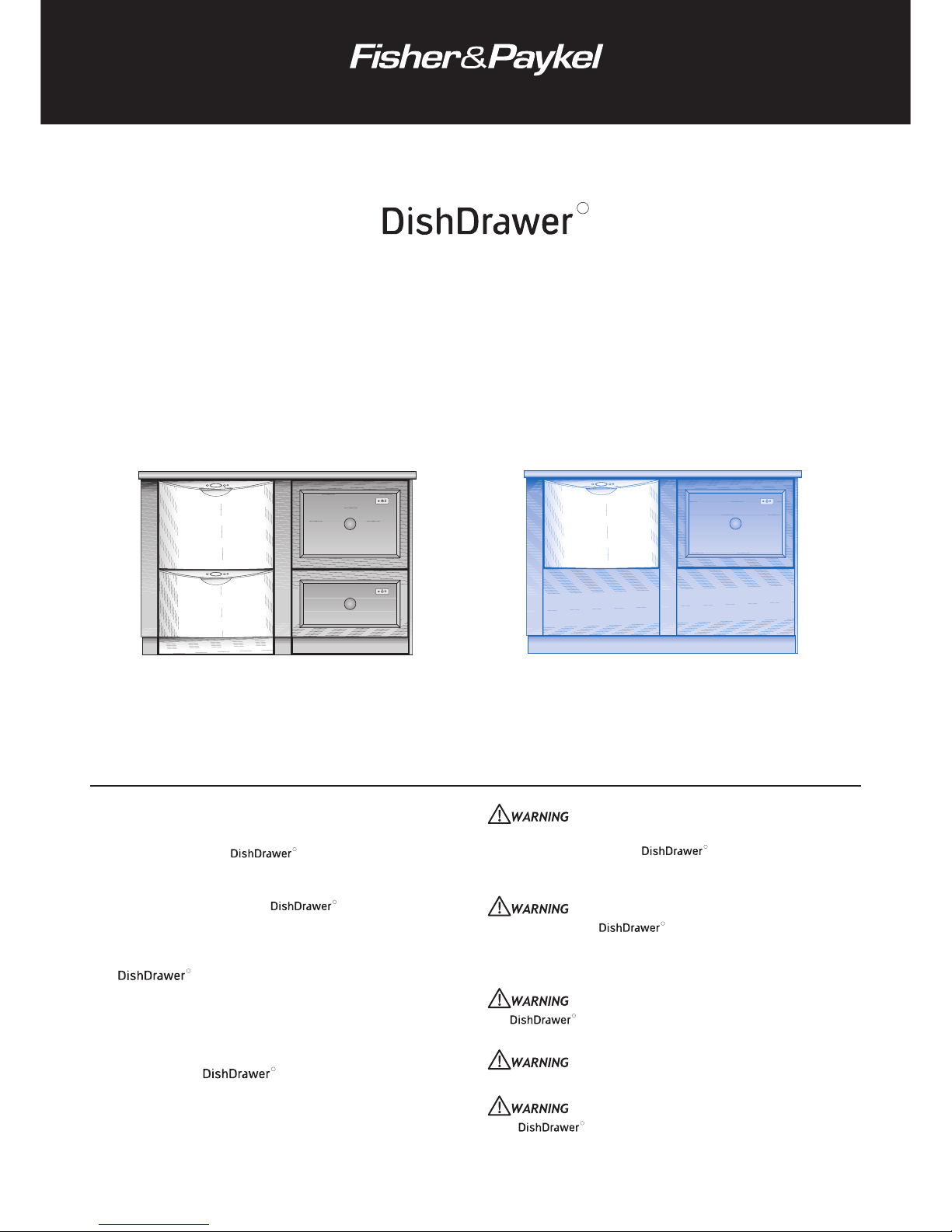
DOUBLE MODELS
MODELS DS603 Prefinished DS603I Integrated
MODELS DD603 Prefinished DD603I Integrated
SINGLE MODELS
GROUNDING INSTRUCTIONS
A) This appliance must be grounded. In the event of malfunction or
breakdown, grounding will reduce the risk of electric shock by
providing a path of least resistance for electric current.
Improper connection of the equipment-grounding conductor can result
in a risk of electric shock. Check with a qualified electrician or
service representative if you are in doubt as to whether the appliance
is properly grounded.
BEFORE YOU START - DOUBLE & SINGLE MODELS
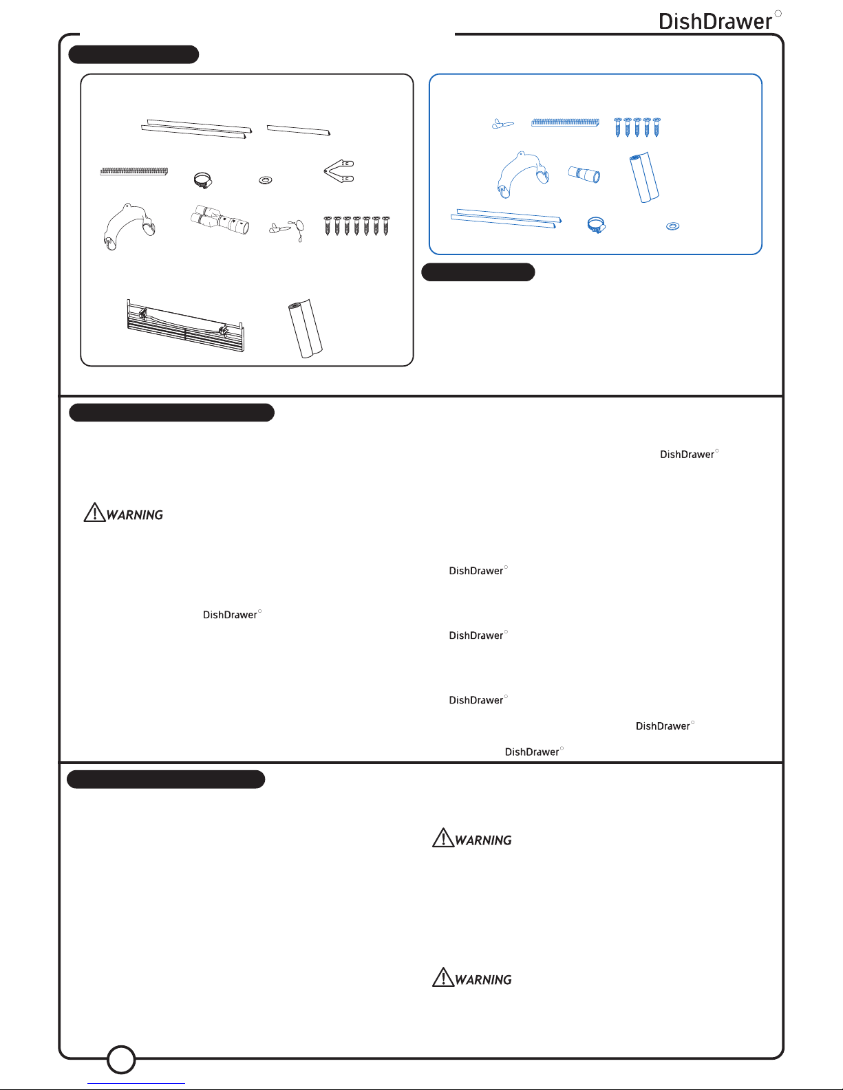
PARTS SUPPLIED
DOUBLE MODELS (INTEGRATED & PREFINISHED)
INSTALLATION KIT P/N 526676
Drain Hose
Support (1)
Drain Hose
Joiner (1)
Wire
Clips (2)
Installation
Tabs (2)
Phillips 16mm
Screws (7)
Prefinished
Toe Kick (1)
Moisture
Protection
Tape (1)
Drain Hose
Support (1)
Drain Hose
Joiner (1)
Wire
Clips (1)
Phillips 16mm
Screws (5)
Moisture
Protection
Tape (1)
SINGLE MODELS (INTEGRATED & PREFINISHED)
INSTALLATION KIT P/N 526676
TOOLS NEEDED
Wooden Chopping Board Drill & No.2 Phillips Bit
Tape Measure No.2 Phillips Screwdriver
Spirit Level Flat Screwdriver
Safety Glasses Adjustable Wrench or M5 Socket
Utility Knife Ø1
1
/2” (38mm) Hole Saw
Pencil Side Cutting Pliers
Sandpaper
INSTALLATION PREPARATION
ELECTRICAL PREPARATION
A) The switched power outlet for the appliance should be installed in a
cabinet or on a wall adjacent to the under bench space in which the
appliance is to be installed. Note: The power outlet must be
accessible after installation.
There should be an opening through the partition between the
compartments mentioned in A) that is large enough for the
attachement plug to fit through. The largest dimension of the opening
should not be more than 1
1
/2” (38mm).
B) The power outlet should be positioned between 6” (150mm) and
18” (450mm) from the cavity.
PLUMBING & DRAINAGE PREPARATION
A) A readily accessible valve must be installed in the water supply pipe.
B) If the supply pressure exceeds 145 psi (1000kPa), then a pressure
limiting valve must be used.
C) Review Plumbing Options on pages 4 & 6. Choose a method that best
suits your needs.
D) A Drain Hose extension Kit P/N 525798 will extend the drain hose(s)
by 141
3
/4” (3.6m). The kit is available from the nearest
Fisher & Paykel Authorized Service Agent.
R
CAVITY PREPARATION
A) It is required that all cabinetry surrounding the is sealed
with an oil based paint or moisture-proof polyurethane to prevent
possible steam damage. The air in the cavity can get very hot and
humid (saturated at 122
o
F/50oC)
B) The self-adhesive moisture protection tape must be applied to the
underside of the countertop to prevent moisture damage, (refer to
cavity diagram pg 3 or 5). Be sure surfaces are dry and dust-free
prior to application.
C) Be sure the cavity provides sufficient material to secure the
using the mounting tabs (refer to step 1, page 7). If
there is nothing to screw to, add something. See page 3 or 5 for
screw locations.
D) The services hole MUST be immediately adjacent to the rear lower
corner of the cabinetry. If not, the hoses will prevent the
being pushed back into the cavity all the way. The hole
can be located on either side depending on the location of the
services.
E) On corner installations, ensure that there is a gap between the
adjacent cabinetry (e.g. door knobs) and the sides of the open
. A
1
/2” (12.7mm) minimum gap is required.
F) If installing multiple products side by side a minimum
3
/32” (2.5mm)
clearance must be maintained around the s.
G) Be sure the cavity sides are plumb (vertical) as this will assist with
levelling the .
R
RRRRR
ELECTRICAL INFORMATION
POWER SUPPLY CORD
A) Care should be taken when the appliance is installed or
removed to reduce the likelihood of damage to the power
supply cord.
2
B) This appliance is equipped with a power supply cord having an
equipment-grounding conductor and an earthing plug. The power
supply plug must be plugged into an appropriate outlet that is installed
and earthed in accordance with all local Codes and Ordinances.
Do not modify the power supply plug provided with the appliance - if
it will not fit the outlet, have a proper outlet installed by a qualified
electrician. Do not use an extension cord, adaptor plug or multiple
outlet box.
B) If the power supply cord is damaged, it must be replaced by
the Manufacturer, Service Agent or a similarly qualified person
in order to avoid a hazard.
R
Washer
(1)
Clamp
(1)
Edge Protector (1)
Flexible Extrusion
for Sides (2)
Flexible Extrusion
for Top (1)
Edge
Protector (1)
Flexible Extrusion for Sides (2)
Clamp (1) Washer (1)
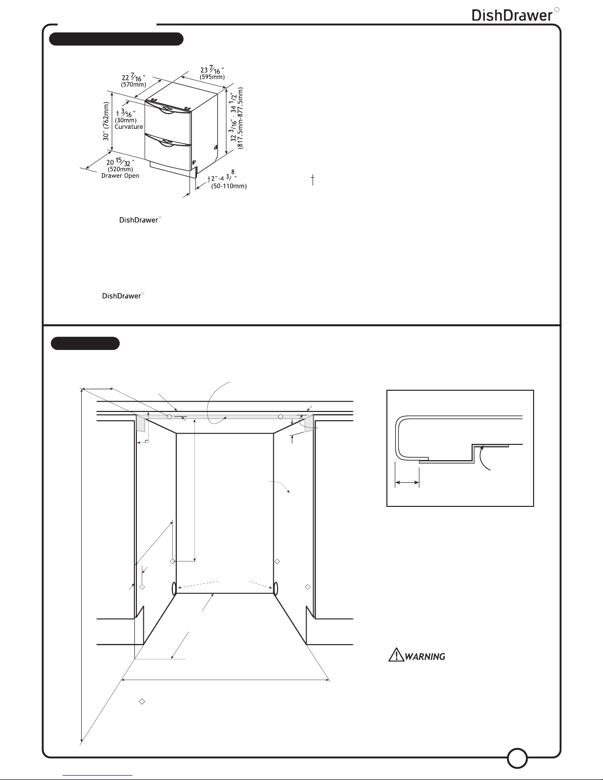
DOUBLE MODELS
SERVICES SPECIFICATIONS
WATER PRESSURE
DRAIN CONNECTION
Drain Hose Joiner to suit Ø3/4”± 5/64” and Ø5/8”± 5/64” waste tees.
ELECTRICAL CONNECTION
110-120 VAC power outlet, 9 Amps Minimum.
TOE KICK DEPTH
Prefinished 2”-43/8” (50-110mm); Integrated 5” (127mm) less the Toe Kick
Panel thickness. Minimum Panel thickness using the supplied screws is
3
/8” (9mm).
# DOOR FRONT HEIGHT
Prefinished 30” (762mm); Integrated 281/4” (717.5mm) minimum.
LENGTH OF SERVICES
Drain hose - 889/16” (2250mm)
Inlet hose - 68
7
/8” (1750mm)
Power supply cord - 44” (1965mm)
NOTE: Services approximately exit product 7
7
/16” (189mm) from left;
21
5
/8” (550mm) from front; 311/4” (793mm) from top.
Maximum Minimum
Water Softener Models 145 p.s.i. (1000kPa) 14.5 p.s.i. (100kPa)
Other Models 145 p.s.i. (1000kPa) 4.3 p.s.i. (30kPa)
THE CAVITY
+
+
+
+
Screw 9/16”
(14mm)
From front
of cabinetry
These marks indicate mounting tab
screw locations (refer to step 1 page 7)
+
+
90°
+
Moisture
Protection Tape
Min thickness
of cavity sides
is
5
/8” (16mm)
Ø 11/2” (38mm)
services hole
can be either
side, immediately
adjacent to
corner
23
5
/8” (600mm)
22
7
/8” (580mm)
throughout cavity
32
13
/
32
”-34
23
/
32
(822.5mm-882.5mm)
3 1/4”
(82.5mm)
3
13
/16”
(97mm)
19
7
/
8
”
(5
0
5
m
m
)
25
3
/
16
” (640.5mm)
tape
1
/2”
(10mm) from
front of
benchtop/
countertop
4”
(
100
m
m
)
NOTE: All depth measurements are taken
from the front face of the adjacent cabinetry.
Typical Installation
countertop
1
/2”
(10mm)
moisture
protection
tape
Be sure the edges of the services hole are
smooth or covered. If the services hole is
through a metal partition the hole must be
protected with the Edge Protector
provided.
*For an Integrated the product depth is specified with an
11
/16” (18mm) Integrated Door Panel thickness.
WATER CONNECTION
Recommended HOT (Maximum 140°F/60°C).
Supplied hose to suit
3
/8” male compression fitting.
WATER SOFTENER MODELS
Refer to your User Guide for how to set up your water
softener.
R
R
3
R
*
#
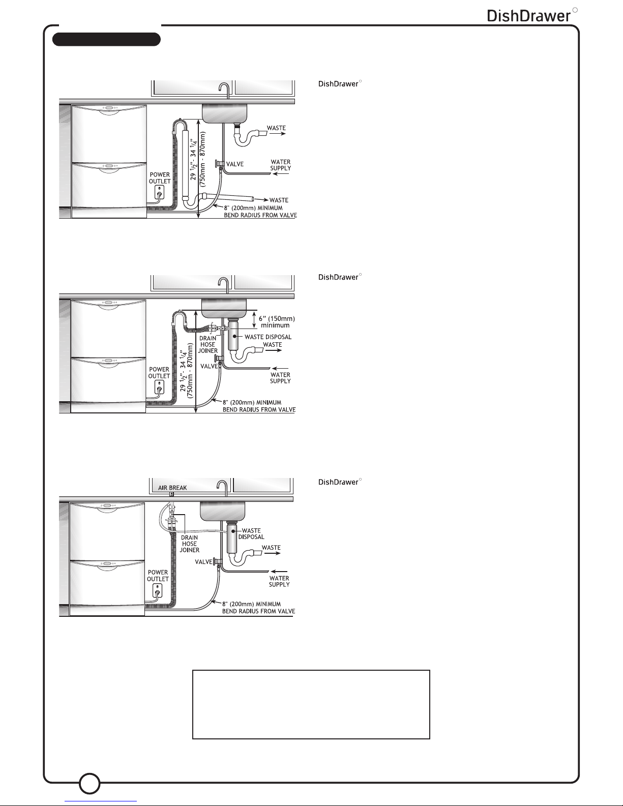
DOUBLE MODELS
PLUMBING OPTIONS
OPTION 1
and Standpipe Ø11/2” (38mm) with Air Gap.
R
OPTION 2
with Waste Disposal.
R
OPTION 3
using Air Break with Drain Hose Joiner.
R
4
R
NOTE: Prefinished Model is shown. There is no variation in plumbing
between Prefinished and Integrated models. Option 1 is the preferred
options. Options 1 & 2 or use of a Dual Inlet Airgap satisfy Kosher
requirements.
 Loading...