

Fisher & Paykel DishDrawer DD24S Installation Instructions Manual
DishDrawer®
Installation instructions
US CA
Important!
SAVE THESE INSTRUCTIONS
The models shown in this document may not be available in all markets and are subject to change at any time. For current details about model and specification availability in your country, please go to our
website www.fisherpaykel.com or contact your local Fisher & Paykel dealer.
SAFETY AND WARNINGS
1
Important safety instructions!
Installation of this DishDrawer® requires basic mechanical and electrical skills.
Be sure to leave these Instructions with the Customer.
Installation must comply with your local building and electricity regulations.
At the completion of the DishDrawer® installation, the Installer must perform
Final Check List.
Remove all packaging materials supplied with the DishDrawer®.
This DishDrawer® is manu factured for indoor use only.
Ensure all water connections are turned OFF. It is the responsibility of the plumber and
electrician to ensure that each installation complies wit h all Codes and Regulati ons.
The DishDrawer® M UST be installed to all ow for future removal from the enclosure if service is required.
The switched power outlet must be outside the DishDrawer® cavit y so that it is accessible after
installation.
Care should be taken when the appliance is installed or removed to reduce the likelihood of damage to
the power supply co rd.
If the DishDrawer® is to be relocated from one installation to another it must be kept upright to avoid
damage from water spillage.
Make sure only new hoses are used for co nnection (supplied with DishDrawer®). Old hoses should not
be reused.
Failure to install the DishDra wer® correctly could invalidate any warranty or liability claims.
If the product is installed in a motor vehicle, boat or similar mobile facility, you must bring the vehicle,
boat or mobile facilit y containing the product to the service shop at your expense or pay the service
technician’s travel to the location of the product.
DD24S models
WARNING!
Electrical hazard
Before installing the DishDrawer®, remove the house fuse or open the circuit
breaker.
If permanently co nnecting the DishDrawer®, be sure the power is isolated and
the DishDrawer® unplugged.
GROUNDING INSTRUCTIONS
This appliance must be grounded. In the event of a malfunction or breakdown,
grounding will reduce the risk of electric shock by providing a path of least
resistance for electric current. This appliance is equipped with a cord having
an equipment-grounding conduc tor and a grounding plug. The plug must be
plugged into an appropriate outlet that is installed and grounded in accordance
with all l ocal codes and ordinances. WARNING - Improper connection of the
equipment-grounding conductor can result
in a risk of electric shock. Check with
a qualied electrician or service representative if you are in doubt as to whether
the appliance is p roperly grounded.
If the DishDrawer is installed as a permanently connected appliance:
GROUNDING INSTRUCTIONS - This appliance must be connected to a grounded
metal, permanent wiring s ystem, or an equipment-groounding conductor must
be run with the circuit conductors and connected to the equipment-grounding
terminal or lead on the appliance.
Do not modif y the power supply plug provi ded with the appliance - if it will not
t the outlet, have a proper outlet insta lled by a qualied electrician. Do not use
an extension cord, adapter plug or multiple outlet box.
Failure to follow this advice may resul
t in electrical shock or death.
WARNING!
Cut hazard
Take care - panel edges are sharp.
Failure to use caution could result in injury or cuts.
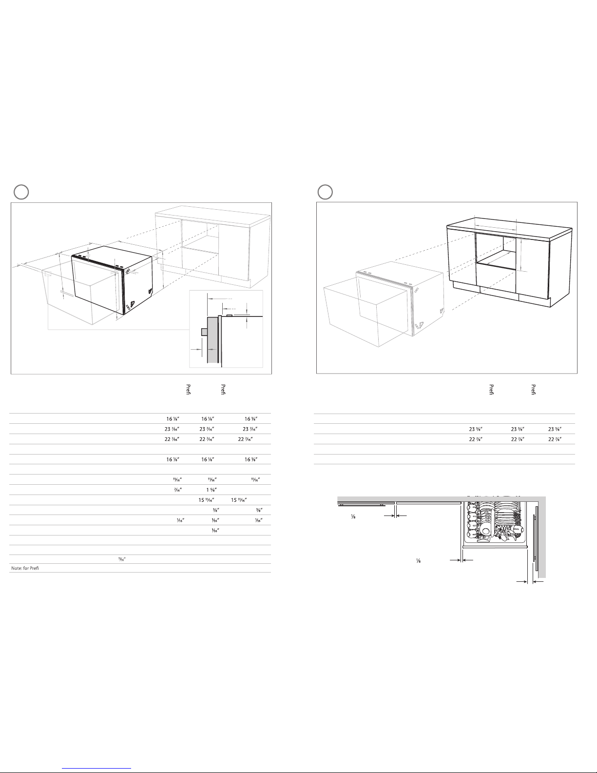
Minimum clearances (inches (mm))
” (2.5 mm)
” (2.5 mm)
½
” (13 mm)
32
SNOISNEMID YRTENIBACSNOISNEMID TCUDORP
A
B
C
E
D
F
G
H
J
K
L
Product dimensions (inches (mm))
nished
LCD
DD24S
nished
Flat door
DD24S
Integrated
DD24S
A
overall height* of product
(409) (409) (409)
B
overall width of product
(595) (595) (595)
C
overall depth of product (excl. curvature/handle)
(570) (570) (570)**
D
depth of drawer (open) (excl. curvature/handle)
20 ½ ” (520) 20 ½ ” (520) 20 ½ ” (520)
E
height* of chassis
(409) (409) (409)
F
depth of chassis
21 ¾ ” (552) 21 ¾ ” (552) 21 ¾ ” (552)
G
depth of drawer front panel (excl. curvature/handle)
(18) (18) (18)
H
depth of curvature or handle
(11) (41) n/a
I
height of drawer front
15 ½ ” (394) (398) (398) min
J
height of venting area at base of product
¼ ” (7) (9) (9)
K
height of installation bracket slots (on top of chassis)
(2) (2) (2)
L
height* of top of drawer to top of chassis
¼ ” (7) (2) n/a
*Chassis heights include bracket slots ** Panel thickness - (18 mm)
nished Flat door models, the height from the top of handle to the top of door - 2 ½ ” (64 mm)
I
Installation diagrams for ill ustration purposes only
A
B
C
Cabinetry dimensions (inches (mm))
nished
LCD
DD24S
nished
Flat door
DD24S
Integrated
DD24S
A
inside height of cavity
16 ¼ ” (412) 16 ¼ ” (412) 16 ¼ ” (412)
B
inside width of cavity
(600) (600) (600)
C
inside depth of cavity
(580) (580) (580)
K
F
C
H
Installation diagrams f or illustration purposes only
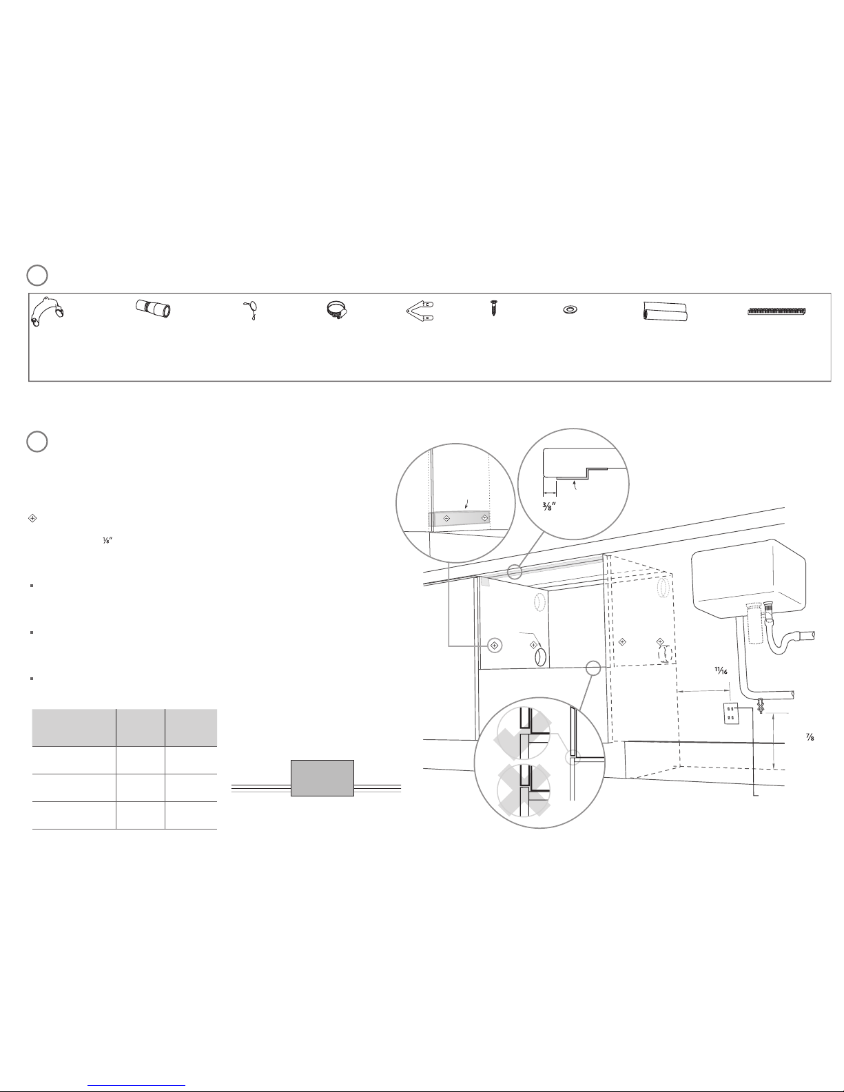
PARTS SUPPLIED
Clamp (1)
Wire clip (1)
Phillips
16 mm
screws (7)
Top mounting
brackets (2)
Drain hose
support (1)
Moisture protec tion
tape (1)
(to prevent m oisture
damage)
Drain hose
joiner (1)
Washer (1)
Edge Protector (1)
(if service hole
partition is metal)
4
2” x 4”
Note: Services can be located
either side of DishDrawer®.
Important!
Adjacent cabinetry must not
extend above cavity base
110-120 VAC
max. 15 A
min.
7 ”
(
200 mm)
(
10 mm)
max.
17 ”
(
450 mm)
Water supply
max. ø
1 ½ ” (
38 mm)
Moisture
protection
tape must
be applied.
If no side partition,
use a brace for
securing.
*
*
If the Drain hose(s) supplied are not long enough to reach your services, you must use a Drain Hose Extension Kit P/N 525798 which will extend the drain hose(s) by 11’ 10” (3.6m). The kit is available from the nearest Fisher & Paykel
Authorized Service Agent, or Toll free 1.888.936.7872 or www.fisherpaykel.com.
5
Important!
Be sure the edges of the services hole are smooth or covered. If the services hole is through a metal
partition the hole must be protected with the Edge protector supplied to prevent damage to the
power cord or hoses.
These marks indicate formed bracket screw locations.
Note: To align drawer front to adjacent cabinetry, the product to countertop clearance can
be increased to
(
3 mm).
Preferred position. If adequate clearance, services hole can be higher.
If hole is higher, ensure drain hose(s) are routed straight into the waste connection.
Water Connection
Recommended HOT (Maximum 140°F/60°C).
Supplied hose to suit 3/8” (9 mm) male compression tting.
*
CAVITY PREPARATION
Water Pressure Max Min
Water softener models 1 MPa (145 psi) 0.1 MPa (14.5 psi)
Other models 1 MPa (145 psi) 0.03 MPa (4.3 psi)
Drains will need to be separated to satisfy kosher requirements. We suggest you conrm
acceptability with your local rabbi in respect to kosher installations.
Max. distance of
hoses and cord from
chassis edge
Left hand
side
Right hand
side
Drain hose
79”
(2011 mm)
71”
(1794 mm)
Inlet hose
37”
(1561 mm)
53”
(1344 mm)
Power cord
61”
(936 mm)
28”
(719 mm)
Left hand
side
Right hand
side
 Loading...