

Fisher & Paykel DD60DHB7, DD60DCW7, DD60DHW7, DD60DCM7, DD60DDFX7 Installation Instructions Manual
...
NZ AU GB IE
590200D 04.13
DD60D 7 models
INSTALLATION INSTRUCTIONS
DishDrawer
TM
dishwasher
2
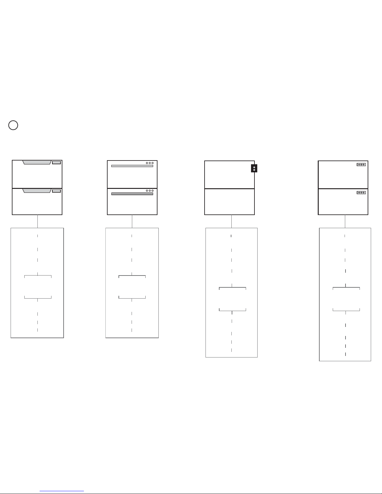
FOLLOW THE INSTALLATION SEQUENCE RELEVANT TO YOUR MODEL
1
PRODUCT & CABINETRY
DIMENSIONS
DD60DC(H)X7
DD60DC(H)W7
DD60DC(H)B7
DD60DCM7
PARTS SUPPLIED
CAVITY PREPARATION
MAXIMUM DISTANCE OF HOSES
& CORD FROM CHASSIS EDGE
SECURE WITHOUT
DRAWER REMOVAL
RECOMMENDED
METHOD (a)
ALTERNATIVE
METHOD (b)
SECURE BY
DRAWER REMOVAL
CHOOSE
DRAINAGE OPTION
FINAL CHECKLIST
CONNECT TO WATER & ELECTRICITY
TROUBLESHOOTING
Classic
PRODUCT & CABINETRY
DIMENSIONS
DD60DDF(H)X7
DD60DDFM7
CHOOSE
DRAINAGE OPTION
FINAL CHECKLIST
CONNECT TO WATER & ELECTRICITY
PARTS SUPPLIED
CAVITY PREPARATION
MAXIMUM DISTANCE OF HOSES
& CORD FROM CHASSIS EDGE
SECURE WITHOUT
DRAWER REMOVAL
RECOMMENDED
METHOD (a)
ALTERNATIVE
METHOD (b)
SECURE BY
DRAWER REMOVAL
TROUBLESHOOTING
Designer
DD60DI7
PRODUCT & CABINETRY
DIMENSIONS
CUSTOM PANEL CALCULATIONS
PARTS SUPPLIED
CHOOSE
DRAINAGE OPTION
FINAL CHECKLIST
CONNECT TO WATER & ELECTRICITY
CAVITY PREPARATION
MAXIMUM DISTANCE OF HOSES
& CORD FROM CHASSIS EDGE
INSTALL THE FRONT PANELS
TROUBLESHOOTING
SECURE WITHOUT
DRAWER REMOVAL
RECOMMENDED
METHOD (a)
ALTERNATIVE
METHOD (b)
SECURE BY
DRAWER REMOVAL
Integrated with remote control
CHOOSE
DRAINAGE OPTION
FINAL CHECKLIST
CONNECT TO WATER & ELECTRICITY
DD60DHI7
PRODUCT & CABINETRY
DIMENSIONS
CUSTOM PANEL CALCULATIONS
PARTS SUPPLIED
CAVITY PREPARATION
MAXIMUM DISTANCE OF HOSES
& CORD FROM CHASSIS EDGE
INSTALL THE FRONT PANELS
& BADGE CONTROLS
TROUBLESHOOTING
SECURE WITHOUT
DRAWER REMOVAL
RECOMMENDED
METHOD (a)
ALTERNATIVE
METHOD (b)
SECURE BY
DRAWER REMOVAL
Integrated with badge controls
ONLY AVAILABLE IN NZ AU ONLY AVAILABLE IN GB IE
3
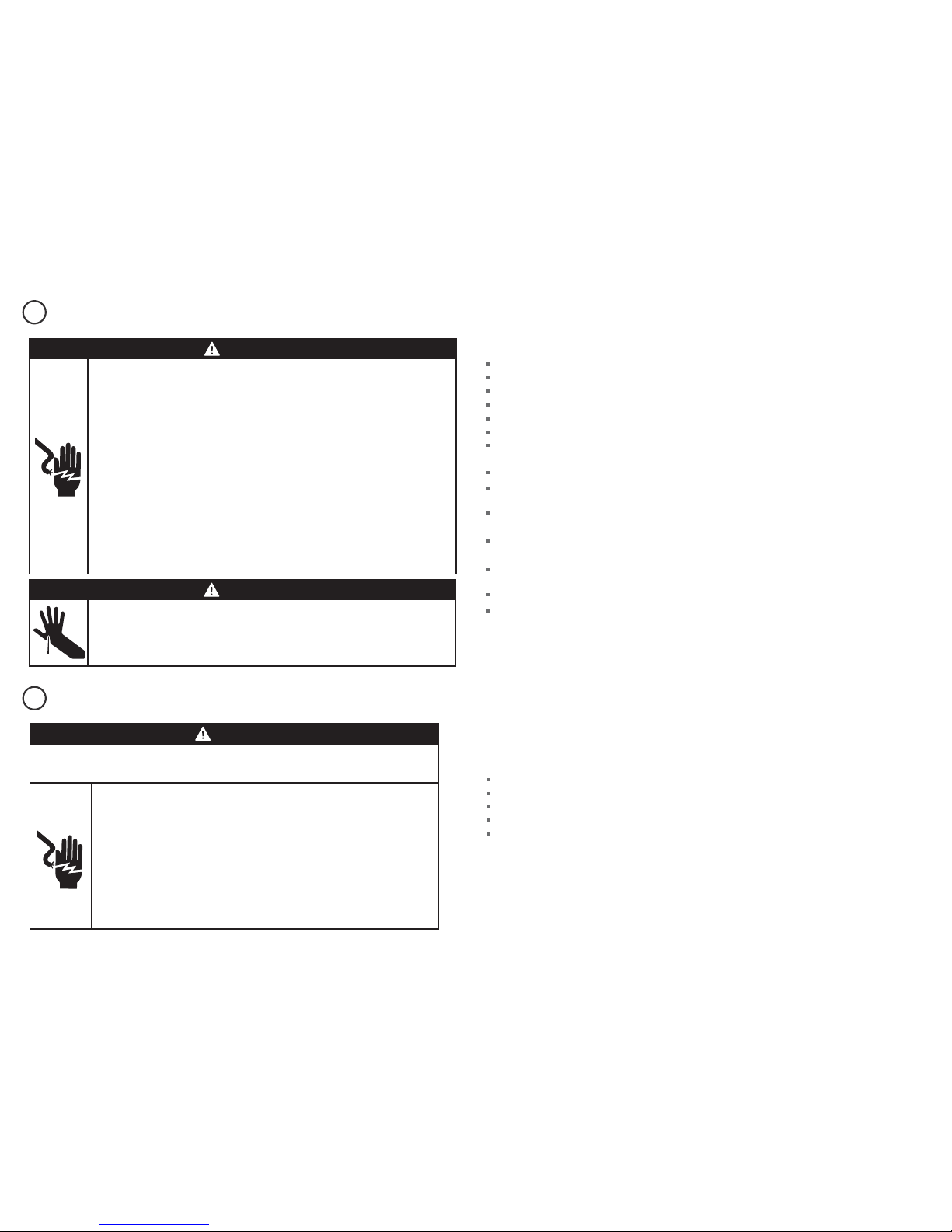
SAFETY AND WARNINGS - ALL MODELS
ADDITIONAL SAFETY AND WARNINGS - INTEGRATED MODELS ONLY
2a
2b
WARNING!
Electrical shock hazard
Before installing the dishwasher, remove the house fuse or open the circuit
breaker.
This appliance must be earthed. In the event of a malfunction or breakdown,
earthing will reduce the risk of electric shock by providing a path of least
resistance for electric current. This appliance is equipped with a cord having an
equipment-earthing conductor and an earthing plug. The plug must be plugged
into an appropriate outlet that is installed and earthed in accordance with all
local codes and ordinances. WARNING- Improper connection of the equipmentearthing conductor can result in a risk of electric shock. Check with a qualified
electrician or service representative if you are in doubt as to whether the
appliance is properly earthed.
Do not modify the power supply plug provided with the appliance - if it will not
fit the outlet, have a proper outlet installed by a qualified electrician. Do not use
an extension cord, adapter plug or multiple outlet box.
Failure to follow this advice may result in electrical shock or death.
WARNING!
Cut hazard
Take care - panel edges are sharp.
Failure to use caution could result in injury or cuts.
IMPORTANT SAFETY INSTRUCTIONS!
Installation of this dishwasher requires basic mechanical and electrical skills.
Be sure to leave these Instructions with the Customer.
Installation must comply with your local building and electricity regulations.
At the completion of the dishwasher installation, the Installer must perform the Final Checklist.
Remove all packaging materials supplied with the dishwasher.
This dishwasher is manufactured for indoor use only.
Ensure all water connections are turned OFF. It is the responsibility of the plumber and
electrician to ensure that each installation complies with all Codes and Regulations.
The dishwasher MUST be installed to allow for future removal from the enclosure if service is required.
The switched power outlet must be outside the dishwasher cavity, so that it is accessible after
installation.
Care should be taken when the appliance is installed or removed to reduce the likelihood of damage to
the power supply cord and hoses.
If the dishwasher is to be relocated from one installation to another it must be kept upright to avoid
damage from water spillage.
Make sure only new hoses are used for connection (supplied with the dishwasher). Old hoses should
not be reused.
Failure to install the dishwasher correctly could invalidate any warranty or liability claims.
If the product is installed in a motor vehicle, boat or similar mobile facility, you must bring the vehicle,
boat or mobile facility containing the product to the service shop at your expense or pay the service
technician’s travel to the location of the product.
SAVE THESE INSTRUCTIONS
IMPORTANT SAFETY INSTRUCTIONS!
Read these instructions completely and carefully.
Ensure the product is not plugged in.
Installation of custom panels requires basic mechanical and electrical skills.
Installation must comply with your local building and electricity regulations.
Failure to install the custom panels correctly could invalidate any warranty or liability claims.
SAVE THESE INSTRUCTIONS
Electrical Shock Hazard
WARNING: To reduce the risk of electrical shock, fire, or injury to persons, the
installer must ensure that the dishwasher is completely enclosed at the time
of installation.
Before fitting the front panels and connecting the integrated badges (where
present), the installer must ensure that the dishwasher is disconnected from
the power supply.
After installing the front panels, the installer must ensure that the following
components are electrically earthed: the panel bracket, the integrated badge
(where present) and any custom metal component (e.g. handle) that extends
past the rubber seal.
Failure to follow these warnings may result in electrical shock, injury or fire.
WARNING!
Fitting integrated front panels requires access to electrical service areas.
This work must be performed and certified by a qualified electrical service technician.
4
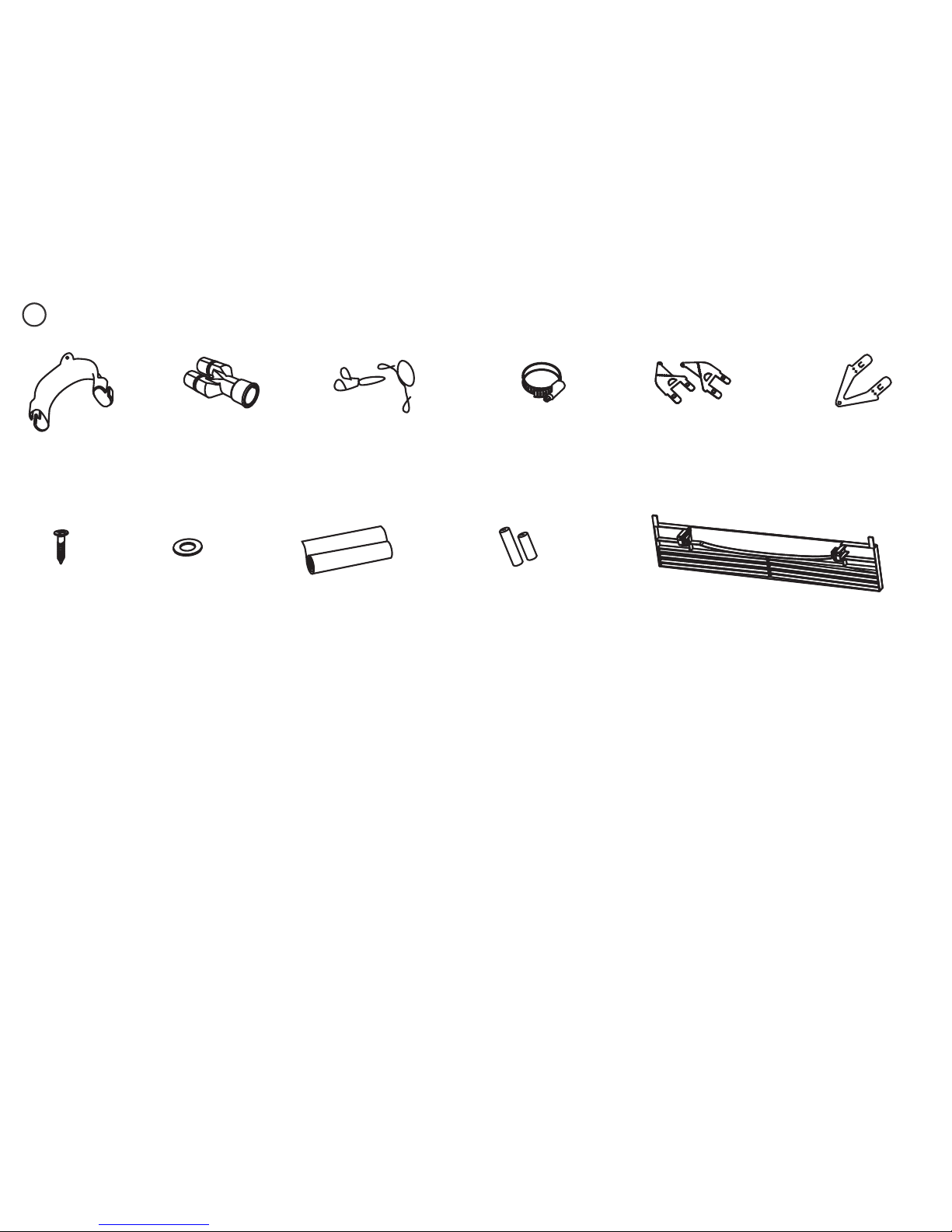
PARTS SUPPLIED - ALL MODELS
3a
If the Drain hoses supplied are not long enough to reach your services, you must use a Drain Hose Extension Kit P/N 525798 which will extend the drain hoses by 3.6 m.
The kit is available from the nearest Fisher & Paykel Authorised Service Centre or our local website listed at the end of this document.
Clamp (1)
(for securing
Drain hose joiner)
Wire clip (2)
(for securing
Drain hose joiner)
Phillips
16 mm
screws (9)
Drain hose
support (1)
Moisture protection
tape (1)
(to prevent moisture
damage)
Drain hose
joiner (1)
Top
mounting
brackets (2)
OPTIONAL
Prefinished toekick (1)Rubber
washer for
inlet hose (1)
(comes already
fitted)
Hexagonal
socket for feet
adjustment (2)
(long & short)
Side mounting
bracket kit
(A and B) (2)
OPTIONAL
5
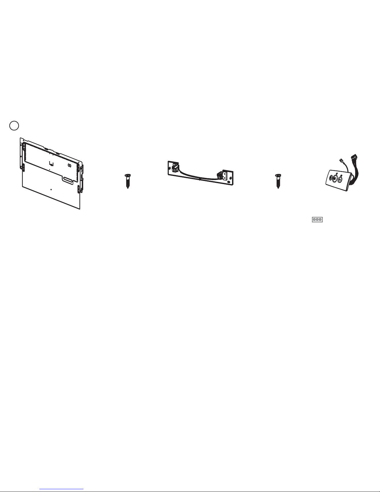
ADDITIONAL PARTS SUPPLIED WITH INTEGRATED MODELS
3b
Panel bracket (2)
(attached to product)
Panel mounting
screws (12)
Toekick
mounting
screws (5)
Toekick mounting bracket (1)
(A custom toekick panel of any
material with thickness
9 - 19 mm can be screwed to the
plastic toekick mounting bracket)
Integrated rectangular
badge (2)
(Satin chrome supplied)
supplied with Integrated
models with badge (GB IE)
only
6
H
K
M
NA
O
O
I
Side
Plan
G
F
J
L
B
CED
4
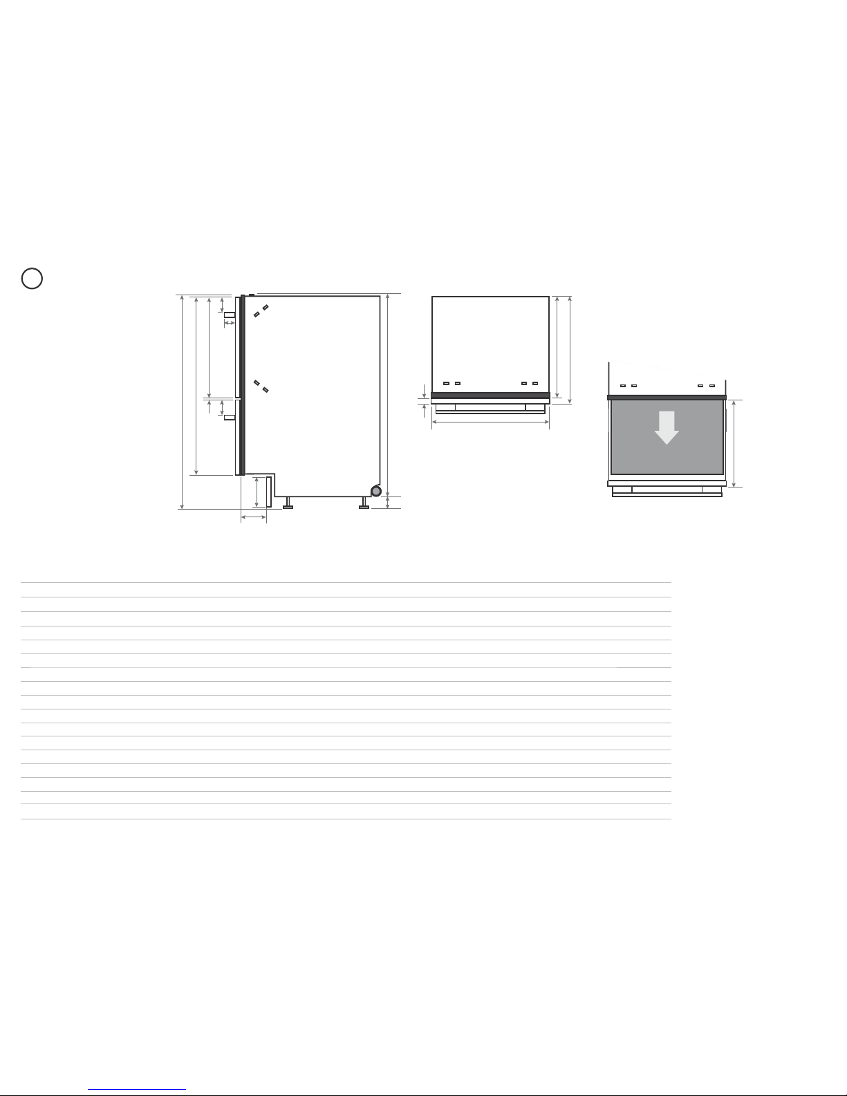
PRODUCT DIMENSIONS
Product dimensions (mm)
Classic
Designer
Integrated
Remote
control
Integrated
Badge
controls
A
overall height1 of product 820-880
2
820-880
2
820-880
2
820-880
2
B
overall width of product 599 599 599 599
C
overall depth of product (excl. handle) 582 571 571
3
571
3
D
depth of chassis (to back of front panel) 553 553 553 553
E
maximum extension of drawer (excl. handle) 556 545 545
3
545
3
F
depth of front panel (excl. handle) 29 18 16 -20 16 -20
G
height1 of chassis 811 811 811 811
H
height of levelling feet 9-69
2
9-69
2
9-69
2
9-69
2
I
depth of handle n/a 41 n/a n/a
J
depth of toekick recess (to back of front panel)
4
30-50 30-50 30-84
5
30-84
5
K
height of upper front panel 394 398 min. 398 min. 398
L
ventilation gap between front panels 5 8 min. 8 min. 8
M
height of toekick panel (adjustable) 70 - 120 70 - 120 70 - 120 70 - 120
N
height of drawer fronts 711 717 min. 717 min. 717
O
height from top of handle to top of front panel n/a 64 n/a n/a
1
includes 2mm high bracket slots 2depending on adjustment of levelling feet 3assuming front panel thickness of 18 mm 4adjustable to match toekick recess on adjoining cabinetry
5
assuming custom toekick panel thickness of 18 mm; if recess is between 50 and 84 mm deep, the panel will need to be cut out - see step ‘Custom panel calculations’
7
5
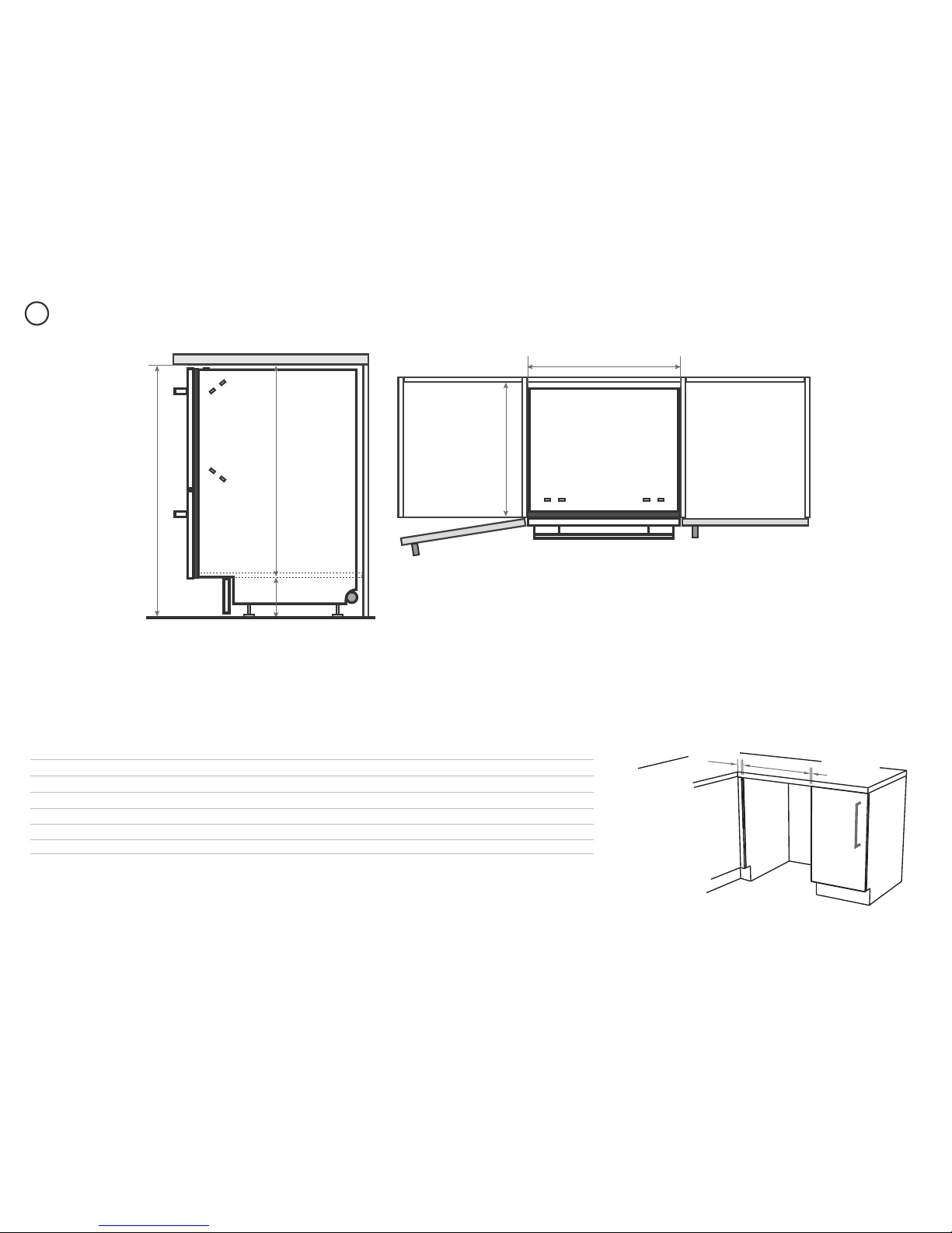
CABINETRY DIMENSIONS
Plan
Side
P
Q
R
S
T
Minimum clearances from adjacent cabinetry
min. 13 mm
clearance
from a corner
cupboard
min. 2 mm
clearance
to adjacent
cupboard door
Cabinetry dimensions (mm)
Classic
Designer
Integrated
Remote control
Integrated
Badge controls
P
inside height of cavity* min. 820 min. 820 min. 820 min. 820
Q
inside width of cavity 600 600 600 600
R
inside depth of cavity min. 560 min. 560 min. 560 min. 560
S
recommended height of adjacent cabinet space 720 720 min. 720 min. 720
T
height of toekick space* 100 - 160 100 - 160 100 - 160 100 - 160
*depending on adjustment of levelling feet
 Loading...