

Fisher Paykel CG305DNGX1N, CG365DLPX1N, CG305DLPX1N, CG244DNGX1N, CG244DLPX1N Installation Manual
Page 1

GAS COOKTOP
CG244D, CG05D & CG65D models
INSTALLATION GUIDE
US CA
590486G 08.17
Page 2

1 SAFETY AND WARNINGS
!
WARNING!
Electrical Shock Hazard
Disconnect product from the mains power supply before servicing. This
appliance is equipped with a three-prong grounding plug for your
protection against shock hazard and should be plugged directly into a
properly grounded power outlet. Do not under any circumstances cut or
remove the grounding prong from this plug.
Failure to follow this advice may result in electrical shock or death.
!
WARNING!
Cut Hazard
Take care - panel edges are sharp.
Failure to use caution could result in injury or cuts.
IMPORTANT SAFETY INSTRUCTIONS
●
This appliance shall be installed in accordance with the installation requirements of the
local gas authority or the appropriate installation code or in the absence of local codes
with the latest National Fuel Gas Code NFPA 54/ANSI Z223.1 or CAN/CSA B149.1,2
(Canada). Local building and electrical codes must be adhered to.
●
Electrical installation must be in accordance with the National Electrical Code, ANSI/
NFPA70 - latest edition or CSA C22.1 (Canada) and/or local codes.
●
Installation in manufactured (mobile) home: installation must conform with the
Manufactured Home Construction and Safety Standard, Title 24 CFR, Part 3280 [formerly
the Federal Standard for Mobile Home Construction and Safety, Title 24, HUD (Part
280)] or, when such standard is not applicable, the Standard for Manufactured Home
Installations, ANSI/NFPA 225, or with local codes where applicable.
●
Installation in Recreational Park Trailers: installation must conform with state or other
codes or, in the absence of such codes, with the Standard for Recreational Park Trailers,
ANSI A119.5.
●
Do not remove permanently affixed labels, warnings, or plates from the product. This
may void the warranty.
●
Flexible appliance connectors shall meet the requirements of ANSI Z21.24 and State
Boards. They shall not exceed 35 1/2 inches (900 mm) in length. In order to avoid hazard,
these appliances must be installed according to these instructions.
●
This appliance must be installed by an authorized person (Warning: this appliance must
be installed by a licensed plumber or gas fitter when within the Commonwealth of
Massachusetts).
●
Please make this information available to the person installing the appliance as it could
reduce your installation costs.
●
Please leave these instructions with the appliance. Inform the customer to retain for
future reference and for the local inspectors’ use.
●
Failure to install the appliance correctly could invalidate any warranty or liability claims.
●
Leak testing of the appliance shall be conducted according to the manufacturer’s
instructions.
Only genuine replacement parts may be used for servicing the appliance. These are
available from your nearest Fisher & Paykel Service Center.
Before you install the appliance, please make sure that
●
the local distribution conditions (nature of gas and pressure) and the adjustment of the
appliance are compatible. For adjustment conditions for this appliance, see ‘Gas rate
summary’ under step 3.
●
a suitable isolating switch is incorporated in the fixed wiring in an acceptable position.
●
the appliance is connected to a power outlet that is electrically grounded in accordance
with local codes or in the absence of local codes, with the National Electric Code ANSI/
NFPA 70 or CSA C22.2 (Canada).
●
there is a power outlet (110-120V 60Hz) within reach of the appliance cable (35 1/2” (900
mm) from the center rear of the appliance). This must be accessible after installation. The
mains power supply cable should not touch any metal parts.
●
the countertop is square and level and no structural members interfere with space
requirements
●
the countertop is made of heat-resistant material.
●
you take note of the following recommended non-combustible materials: 1/4” (6 mm) flame
retardant millboard covered with not less than No. 28 MSG sheet steel, 1/32” (0.4 mm)
stainless steel, 1/32” (0.6 mm) aluminum or 1/32” (0.5 mm) copper.
●
the gas shut-off valve is accessible after installation.
●
if the power supply cable is damaged, it is replaced only by the special cable: Part no.
531954 FLEX TERMINAL BLOCK ASSY US, obtainable from authorized Fisher & Paykel
Service Agents.
IMPORTANT!
SAVE THESE INSTRUCTIONS
The models shown in this installation guide may not be available in all markets and are subject to change at any time. For current details about model and specification availability in your country, please go to our
website www.fisherpaykel.com or contact your local Fisher & Paykel dealer.
1
Page 3

2 PARTS SUPPLIED
Wok stand (1)
SEMI-RAPID SEMI-RAPID
MINI WOK AUX
Small pan support
(1)
(CG305D & CG365D
models only)
SEMI-RAPID SEMI-RAPID
RAPID
CG305D & CG365DCG244D
Fibre washers (1)
DUAL WOK
Elbow 1/2“ NPT
external thread (1)
3 GAS RATE SUMMARY
AUX
Clamping
Regulator (1)
Foam tape (1)
brackets (4)
and screws (4)
High Altitude Installations - CG30D & CG365D models
For installations above 3000’ conversion kits are required:
3,000-6,000’ 534695 KIT HI ALT NG
534697 KIT HI ALT LP
6000’+ 534696 KIT HI ALT NG
534698 KIT HI ALT LP
High Altitude Installations - CG244D models
For installations above 3000’ conversion kits are required:
3,000-6,000’ 535432 KIT HI ALT 3000-6000 NG GOS244
535434 KIT HI ALT 3000-6000 LG GOS244
6000’+ 535433 KIT HI ALT 6000+ NG GOS244
535435 KIT HI ALT 6000+ LG GOS244
Contact your authorized dealer, customer care or refer to the website
listed at the back of this document.
US CA
INJECTOR ORIFICE (MM)
NG 4” H2O (0.15 psi)
LP 11” H2O (0.39 psi)
CG244D 0.9 3500 0.55 3500 1.40 8500 0.75 6700 na na na na 1.55 11100 0.94 11100 na na na na
CG305D 0.9 3500 0.55 3500 1.40 8500 0.75 6700 1.65 11500 0.98 11500 na na na na
CG365D 0.9 3500 0.55 3500 1.40 8500 0.75 6700 1.65 11500 0.98 11500 na na na na
NOMINAL RATING (BTU/HR)
NG LP NG LP NG LP NG LP NG LP
INJECTOR ORIFICE (MM)
AUX SEMI-RAPID RAPID MINI WOK DUAL WOK
NOMINAL RATING (BTU/HR)
INJECTOR ORIFICE (MM)
NOMINAL RATING (BTU/HR)
INJECTOR ORIFICE (MM)
NOMINAL RATING (BTU/HR)
INJECTOR ORIFICE (MM)
NOMINAL RATING (BTU/HR)
INJECTOR ORIFICE (MM)
NOMINAL RATING (BTU/HR)
INJECTOR ORIFICE (MM)
NOMINAL RATING (BTU/HR)
INJECTOR ORIFICE (MM)
NOMINAL RATING (BTU/HR)
INJECTOR ORIFICE (MM)
1.50
1.50
0.70
1.50
1.50
0.70
NOMINAL RATING (BTU/HR)
19000
19000
0.83
0.83
0.50
0.83
0.83
0.50
INJECTOR ORIFICE (MM)
19000
19000
NOMINAL RATING (BTU/HR)
2
Page 4
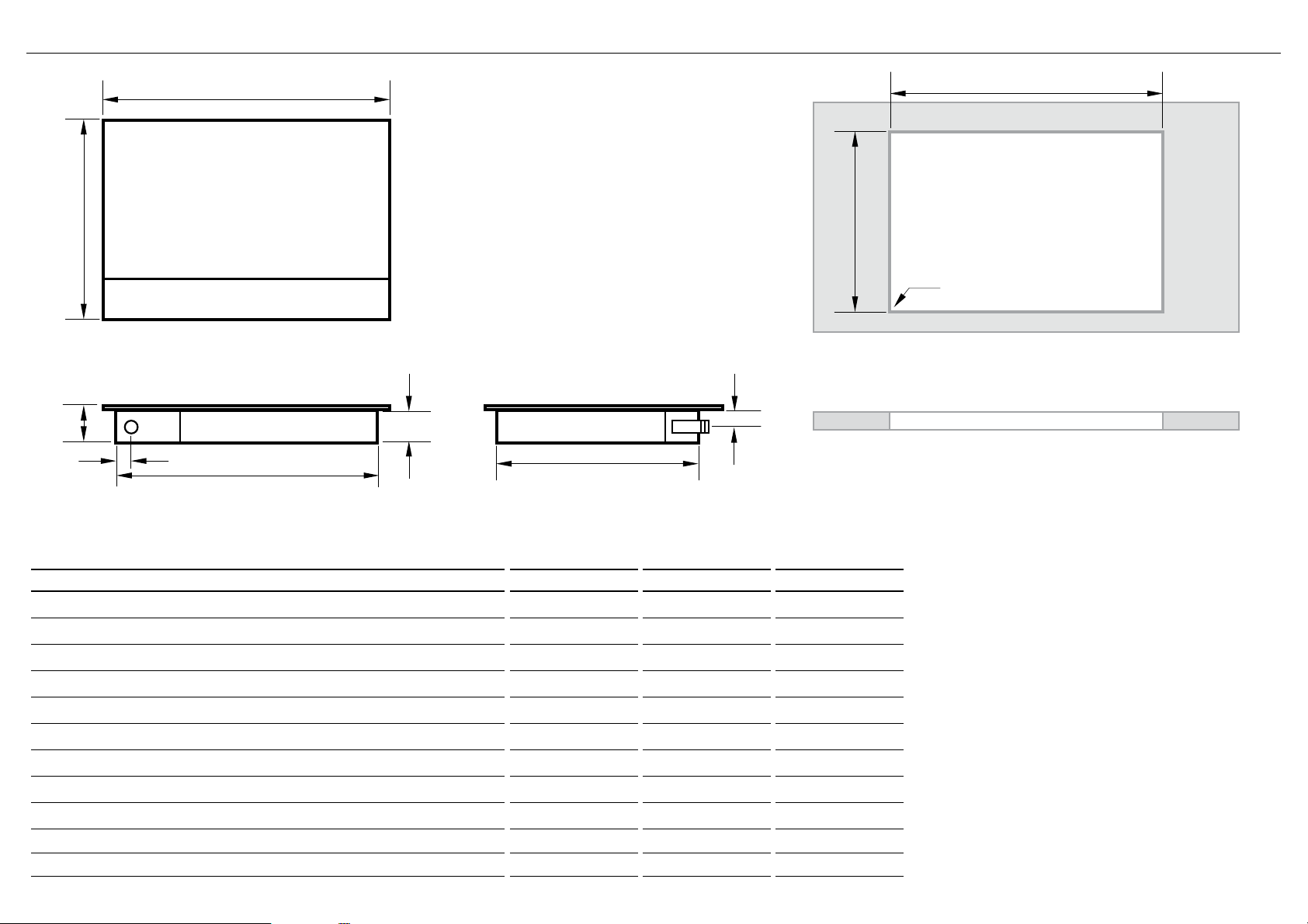
4 PRODUCT & CABINETRY DIMENSIONS
A
K
D
B
E
C
G
F
J
H
I
TOP
Note: Gas inlet connection is located in the
rear right corner.
REAR
PRODUCT DIMENSIONS inches (mm) inches (mm) inches (mm)
Overall height of product (excluding burners, dials and pan supports) 2 1/2” (64) 2 1/2” (64) 2 1/2” (64)
A
Overall width of product
B
Overall depth of product
C
Height of chassis (below top of counter)
D
Width of chassis
E
Depth of chassis
F
Overall width of cutout
G
Overall depth of cutout
H
Corner radius of cutout
I
Distance from top of counter to center of gas inlet on product
J
Distance from edge of chassis to gas inlet on product
K
3
SIDE
CG244D CG305D CG365D
23 5/8” (600) 29 1/2” (749)
20 7/8” (530) 20 7/8” (530)
2 5/16” (59) 2 5/16” (59)
21 7/8” (555) 27 1/2” (698)
19 1/8” (486) 19 5/16” (490)
22 1/16” (560) 27 3/4” (705)
19 5/16” (490) 19 1/2” (495)
max. 3/8” (10) max. 3/8” (10)
1 1/4” (32)
13/16” (21)
1 1/4” (32) 1 1/4” (32)
13/16” (21) 13/16” (21)
35 1/2” (900)
20 7/8” (530)
33 11/16” (856)
34 1/16” (865)
19 5/16” (490)
max. 3/8” (10)
TOP
FRONT
2 5/16” (59)
19 1/8” (486)
Page 5

5 CLEARANCE DIMENSIONS
F
E
H
G
C
I
A
CLEARANCE DIMENSIONS inches (mm) inches (mm) inches (mm)
Minimum clearance from left edge of product to nearest vertical surface 12” (294) 12” (294) 12” (294)
A
Minimum clearance from right edge of product to nearest vertical surface 12” (294) 12” (294) 12” (294)
B
Minimum clearance from rear edge of product to:
C
nearest combustible surface
nearest non-combustible surface*
Minimum clearance from front edge of counter to front edge of product 1 1/4” (32) 1 1/4” (32) 1 1/4” (32)
D
Minimum clearance from cooking surface to combustible surface centered above the cooking surface 30” (762) 30” (762) 30” (762)
E
Maximum overall depth of overhead cabinetry 13” (330) 13” (330) 13” (330)
F
Minimum distance between overhead cabinets installed to either side of product 24” (588) 30” (762) 36” (915)
G
Minimum vertical distance between counter and cabinet extending above the counter 18” (457) 18” (457) 18” (457)
H
Minimum clearance below top of countertop to:
I
nearest combustible surface
F&P oven or nearest non-combustible surface
Maximum distance from the center of the product to the nearest grounded power outlet.
J
The power supply cable must not touch any hot metal surfaces.
* Recommended non-combustible materials are: 1/4” (6 mm) flame retardant millboard covered with not less than No. 28 MSG sheet steel, 0.015” (0.4 mm) stainless steel,
0.024” (0.6 mm) aluminum or 0.020” (0.5 mm) copper.
ISO
D
B
J
FRONT
CG244D CG305D CG365D
3” (74)
1 1/2” (38)
2 3/4” (70)
2 9/16” (65)
35 1/2” (900) 35 1/2” (900) 35 1/2” (900)
7” (178)
1 1/2” (38)
2 3/4” (70)
2 9/16” (65)
7” (178)
1 1/2” (38)
2 3/4” (70)
2 9/16” (65)
4
Page 6

6 DISCARD PACKAGING
Model may vary from illustrations shown
7 FIT THE ELBOW AND WASHER
Recycle responsibly
8 APPLY ADHESIVE FOAM TAPE AROUND EDGE
Foam Tape
1 Turn the cooktop upside down and
Adhesive side
Ensure edge of tape
lines up with outer
edge of cooktop
place it on a soft surface.
2 Spread the seal around the edges,
with the adhesive side facing down
to form a continuous seal around the
cooktop.
3 Using a sharp cutter or trimmer
knife, trim the excess sealing material
around the edge of the cooktop. Take
care not to damage the countertop.
Floating nut Fibre washer
Elbow (1/2 “ NPT external thread)
9 LOWER GENTLY INTO THE CUTOUT
5
Page 7

on
x 4
!0 FIT CLAMPING BRACKETS BASED ON THE COUNTERTOP THICKNESS & SECURE TO COUNTERTOP
view from below
x 4
”- ¾” ¾”- 1 ”
(16-20mm) (20-30mm)
1
”- 1½”
(30-40mm)
½” +
1
(40mm+)
!1 GAS CONNECTION
●
Make sure the connection point will be accessible with the cooktop installed.
●
To enable the gas supply to be readily shut off by the customer, make sure the connection is fitted with an isolating valve
close to the cooktop.
●
The appliance must be isolated from the gas supply piping system by closing its individual shut-off valve during any pressure testing of the
gas supply piping system at test pressures at or less than 1/2 p.s.i. (3.5 kPa).
●
Maximum inlet gas supply pressure 20” W.C. (5 kPa). Minimum gas supply pressure for regulator testing 5” W.C. Natural Gas / 12” W.C LP
gas.
●
A manual shut-off valve must be installed in an accessible location in the gas line external to the appliance for the purpose of turning on or
shutting off gas to the appliance. (In Massachusetts, such shut-off devices should be approved by the Board of State Examiners of Plumbers
& Gas Fitters).
●
Gas connection to the product must use the nipple supplied with a 1/2” NPT external thread. The supplied gas pressure regulator must be
installed where it will be accessible for adjustment. The metal flexible hose used must be new, CSA or UL-approved, and must have a 1/2”
NPT external thread on one end and a 1/2” NPT one on the other
If connecting the gas with a flexible hose
●
Ensure the hose is long enough to allow for removal of cooktop for servicing.
●
Make sure the connector is located as shown in step 5 CLEARANCE DIMENSIONS.
●
The hose assembly must be with an Rp 1/2” (ISO 7-1) female thread connection.
●
The hose assembly must be as short as practicable and comply with the relevant requirements.
●
The hose must not be kinked, subjected to abrasion or permanently deformed.
●
The hose must not be near or in contact with any hot surfaces (e.g. base of metal hotlplate, flue, or chassis of undercounter oven etc.)
Repeat on all the other sides
6
Page 8

!2 CONNECT TO THE GAS SUPPLY
This appliance is factory set for use with Natural Gas at 4” W.C.P. or LP
Gas at 11” W.C.P. Check the label on the underside of the appliance.
Gas regulator
●
For use with a gas pressure regulator as shown.
Pressure
Regulator
shows
Direction of
Gas Flow
!3 LEAK TESTING
●
Leak testing of the appliance shall be conducted according to the manufacturer’s instructions.
●
The appliance and its individual shut-off valve must be disconnected from the gas supply piping system during
any pressure testing of that system in excess of 1/2 psi (3.5kPa).
●
The appliance must be isolated from the gas supply piping system by closing its individual manual shut-off valve
during any pressure testing of the gas supply piping system at test pressures at or less than 1/2 psi (3.5 kPa).
●
Maximum inlet gas supply pressure 20” W.C. (5 kPa)
●
Minimum gas supply pressure for regulator testing 5” W.C. Natural Gas, 12” W.C. LP Gas.
To Cooktop
Regulator
Solid or Flexible
Connector
Shut-Off
Valve
Pipe Stub from
House supply
Cooktop
ON
ON
GAS
GAS
After installing the gas supply and making all connections, check thoroughly for possible leaks:
1 Turn all control dials on unit to “OFF” position.
2 Open the valve on the gas supply.
3 Using a leak detection fluid (eg Rocol leak detection spray), check each gas connection one at a time by spraying
or brushing the solution over the connection. The presence of bubbles will indicate a leak.
4 If necessary, tighten the fitting and recheck for leaks.
5 Turn on burner valve and light each burner.
6 Check for a clear blue flame without yellow tipping. If burners show any abnormalities, check that they are
located properly and in line with the injector orifice.
7
Page 9

!4 AFFIX DUPLICATE DATA LABEL SOMEWHERE
INSTALLATION INSTRUCTIONS
ACCESSIBLE & PLUG COOKTOP IN
Duplicate data label
!6 LEAK TESTING
!5 FIT PAN SUPPORTS
Ensure the pan supports are located securely
and in the correct orientation (refer to User guide)
●
To check that the ignition system operates correctly, light each burner by itself, then all burners in combination.
●
Check for a well-defined blue flame without any yellow tipping.
●
If any abnormality is evident, check that the components of the burner assembly are located properly
●
If proper operation cannot be obtained, contact Customer Care or your nearest F&P Authorized Service Center.
●
The cooktop must not be used by the customer until proper operation has been achieved.
Lifting off
Yellow tip
Good flame
8
Page 10

!7 FINAL CHECKLIST
TO BE COMPLETED BY THE INSTALLER
Have you installed the clamping brackets?
Have you verified that the type of model (factory-set for NG or LP) matches the type of gas at the site of installation?
Have you sealed all connections with gas tape?
Have you used the fibre washer supplied?
Have you leak-tested all connections?
Is the cooktop set to the correct working pressure?
Have you affixed the supplied duplicate data plate label on an adjacent
surface accessible to the customer?
Is the cooktop grounded?
Check that the power supply cord is NOT touching the cooktop.
OPERATION:
Do all burners ignite both individually and in combination?
Are the flames consistent and appropriately sized?
Have you demonstrated the basic operation to the customer?
Complete and keep for safe reference:
Model
Serial No.
Purchase Date
Purchaser
Dealer Address
Installer’s Name
Installer’s Signature
Installation Company
Installation Date
9
Copyright © Fisher & Paykel Appliances 2016. All rights reserved.
The product specifications in this booklet apply to the specific products
and models described at the date of issue. Under our policy of continuous
product improvement, these specifications may change at any time. You
should therefore check with your Dealer to ensure this booklet correctly
describes the product currently available.
Page 11

101112
Page 12

Page 13

Page 14

SURFACE DE CUISSON AU GAZ
Modèles
CG244D, CG05D et CG65D
INSTRUCTIONS D’INSTALLATION
US CA
590486G 08.17
Page 15

1 CONSIGNES DE SÉCURITÉ ET MISES EN GARDE
!
MISE EN GARDE!
Risque de choc électrique
Débranchez l’appareil de l’alimentation électrique avant toute réparation.
Cet appareil est équipé d’une fiche à trois broches avec mise à la terre pour
protéger des chocs électriques. Branchez-la directement dans une prise
électrique avec mise à la terre adéquate. Vous ne devez en aucune circonstance
couper ou retirer la broche de mise à la terre de cette fiche.
Le non-respect de cette consigne peut entraîner un choc électrique ou la mort.
!
MISE EN GARDE!
Risque de coupure
Attention, les bords du panneau sont tranchants.
Des blessures ou des coupures peuvent se produire si vous ne faites pas
preuve de prudence.
CONSIGNES DE SÉCURITÉ IMPORTANTES!
●
Cet appareil devra être installé conformément aux exigences des réglementations
locales relatives augaz ou des codes d’installation appropriés, ou en l’absence de codes
locaux, de la norme NFPA 54/ANSI Z223.1 ou CAN/CSA B149.1,2 de la dernière édition
du National Fuel Gas Code du Canada. Les codes locaux du bâtiment et de l’électricité
doivent être respectés.
●
Toute installation électrique doit être conforme à la norme ANSI/NFPA70 de la dernière
édition du Codenational de l’électricité ou à la norme CSA C22.1 (Canada) et/ou aux
codes locaux.
●
Installation dans une maison préfabriquée (mobile): l’installation doit être effectuée
conformément à la norme Manufactured Home Construction and Safety Standard,
Titre24 CFR, Partie3280 [anciennement Federal Standard for Mobile Home Construction
and Safety, Titre24, HUD (Partie280)] ou, lorsqu’une telle norme est inapplicable, à
la norme Standard for Manufactured Home Installations, ANSI/NFPA 225, ou aux codes
locaux en vigueur.
●
Installation dans une caravane de parc: l’installation doit être effectuée conformément
aux codes de l’État et autres codes, ou en l’absence de tels codes, à la norme Standard
for Recreational Park Trailers, ANSI A119.5.
●
Ne retirez pas les étiquettes, mises en garde ou plaques signalétiques apposées sur
l’appareil. Cela pourrait entraîner l’annulation de la garantie.
●
Les raccords flexibles de l’appareil doivent être conformes à la norme ANSI Z21.24 et
aux règlements de commissions d’État. Leur longueur ne doit pas dépasser 351/2po
(900mm). Installez ces appareils conformément aux instructions afin d’éviter tout
danger.
●
●
Cet appareil doit être installé par un technicien autorisé (mise en garde: dans les limites
de l’ÉtatduMassachusetts, cet appareil doit être installé par un monteur d’installation au
gaz ou plombierautorisé).
●
Remettez ces instructions à la personne qui installera l’appareil. Cela pourrait réduire vos
coûts d’installation.
●
Laissez ces instructions avec l’appareil. Demandez au client de les conserver pour toute
référence ultérieure ou vérification des inspecteurs locaux.
●
Le fait de ne pas installer l’appareil de façon adéquate pourrait entraîner l’annulation de
toute garantieou réclamation.
●
La vérification des fuites doit être effectuée conformément aux instructions du fabricant.
●
Utilisez uniquement des pièces de remplacement authentiques pour effectuer l’entretien
ou lesréparations de l’appareil. Vous pouvez vous les procurer auprès d’un Centre de
service Fisher& Paykel de votre région.
Avant d’installer l’appareil, assurez-vous que:
●
les conditions de distribution locales (nature du gaz et pression) et le réglage de l’appareil
sont compatibles. Pour connaître les conditions de réglage de cet appareil, voir ‘Tableau de
débit des gaz’ àl’étape3.
●
le câblage fixe comporte un interrupteur de sectionnement approprié, installé dans une
position convenable.
●
l’appareil est branché à une prise électrique mise à la terre en conformité avec les codes
locaux ou, enl’absence de tels codes, avec la norme ANSI/NFPA70 ou CSA C22.2 du Code
national de l’électricité(Canada).
●
une prise électrique (110-120V 60Hz) se trouve à proximité du câble de l’appareil
(351/2po (900mm) à partir de la partie centrale à l’arrière de l’appareil). Cette prise doit
demeurer accessible après l’installation. Le câble d’alimentation ne doit toucher aucune
pièce métallique.
●
le comptoir est au niveau et bien droit, et aucune pièce de charpente ne nuit aux exigences
dedégagement.
●
le comptoir est fait d’un matériau résistant à la chaleur.
●
vous prenez note de ces matériaux incombustibles recommandés: panneau de celloderme
ignifuge de 1/4po (6mm) couvert d’une tôle d’acier n°28 MSG (minimum), d’acier
inoxydable de 1/32po (0,4mm),
●
d’aluminium de 1/32po (0,6mm) ou de cuivre de 1/32po (0,5mm).
●
le robinet d’arrêt du gaz est accessible après l’installation.
●
si le câble d’alimentation est endommagé, il doit être remplacé uniquement par un câble
spécial: Pièce n°531954 FLEX TERMINAL BLOCK ASSY US, disponible auprès des agents
de service autorisés deFisher&Paykel.
IMPORTANT!
CONSERVEZ CES INSTRUCTIONS
Les modèles illustrés dans ce document pourraient ne pas être offerts par tous les détaillants et sont sujets à modifications sans préavis. Pour les plus récentes informations sur la disponibilité des modèles et des
caractéristiques dans votre pays, veuillez visiter notre site Web local à l’adresse indiquée à la fin de ce document, ou contacter votre détaillant Fisher&Paykel local.
1
Page 16

2 PIÈCES FOURNIES
Support de wok (1)
Petite pièce d’appui (1)
Rondelle en fibre (1)
(Modèles CG305 et
CG365 seulement.)
3 TABLEAU DE DÉBIT DES GAZ
SEMI-RAPIDE SEMI-RAPIDE SEMI-RAPIDE SEMI-RAPIDE
DOUBLE POUR
WOK
MINI WOK AUXILIAIRE
RAPIDE
CG305D et CG365DCG244D
AUXILIAIRE
Coude avec filetage
NPT externe de
1/2po (12,5mm) (1)
Installations en haute altitude - Modèles CG30D & CG365D
Pour les installations au-dessus de 3000pi, des ensembles deconversion sont requis:
3000-6000pi 534695– ENSEMBLE HAUTE ALTITUDE POUR GN
534697– ENSEMBLE HAUTE ALTITUDE POUR GPL
6000pi+ 534696– ENSEMBLE HAUTE ALTITUDE POUR GN
534698– ENSEMBLE HAUTE ALTITUDE POUR GPL
Installations en haute altitude - Modèles CG244D
Pour les installations au-dessus de 3000pi, des ensembles deconversion sont requis:
3000-6000pi 535432 KIT HI ALT 3000-6000 NG GOS244
535434 KIT HI ALT 3000-6000 LG GOS244
6000pi+ 535433 KIT HI ALT 6000+ NG GOS244
535435 KIT HI ALT 6000+ LG GOS244
Communiquez avec votre détaillant autorisé ou l’assistance à laclientèle, ou consultez notre
site Web, à l’adresse indiquée à l’arrière de ce document.
Supports de
retenue (4)
et vis (4)
Régulateur (1)
Isolant adhésif (1)
US CA
ORIFICE D’INJECTION (MM)
VALEUR NOMINALE
(BTU/HEURE)
ORIFICE D’INJECTION (MM)
VALEUR NOMINALE
(BTU/HEURE)
GN 4po (102mm) H2O
(0,15psi)
GPL 11po (279mm) H2O
(0,39psi)
CG244D
CG305D
CG365D 0.9 3500 0.55 3500 1.40 8500 0.75 6700 1.65 11500 0.98 11500 na na na na
0.9 3500 0.55 3500 1.40 8500 0.75 6700 na na na na 1.55 11100 0.94 11100 na na na na
0.9 3500 0.55 3500 1.40 8500 0.75 6700 1.65 11500 0.98 11500 na na na na
AUXILIAIRE SEMI-RAPIDE RAPIDE MINI WOK DOUBLE POUR WOK
GN GPL GN GPL GN GPL GN GPL GN GPL
ORIFICE D’INJECTION (MM)
VALEUR NOMINALE
(BTU/HEURE)
ORIFICE D’INJECTION (MM)
VALEUR NOMINALE
(BTU/HEURE)
ORIFICE D’INJECTION (MM)
VALEUR NOMINALE
(BTU/HEURE)
ORIFICE D’INJECTION (MM)
VALEUR NOMINALE
(BTU/HEURE)
ORIFICE D’INJECTION (MM)
VALEUR NOMINALE
(BTU/HEURE)
ORIFICE D’INJECTION (MM)
VALEUR NOMINALE
(BTU/HEURE)
ORIFICE D’INJECTION (MM)
VALEUR NOMINALE
(BTU/HEURE)
ORIFICE D’INJECTION (MM)
1.50
1.50
0.70
1.50
1.50
0.70
19000
19000
0.83
0.83
0.50
0.83
0.83
0.50
VALEUR NOMINALE
19000
19000
(BTU/HEURE)
2
Page 17

4 PRODUCT & CABINETRY DIMENSIONS
A
K
D
B
E
C
G
F
J
H
I
3
DESSUS
Remarque: Le raccord d’admission de gaz
est situé dans le coin arrière droit.
ARRIÈRE
Dimensions du produit et des armoires
Hauteur hors tout du produit (excluant les brûleurs, les boutons et les pièces d’appui)
A
Largeur hors tout du produit
B
Profondeur hors tout du produit
C
Hauteur du châssis (sous la surface du comptoir)
D
Largeur du châssis
E
Profondeur du châssis
F
Largeur hors tout de l’ouverture
G
Profondeur hors tout de l’ouverture
H
Rayon du coin de l’ouverture
I
Distance entre la surface du comptoir et le centre de l’admission de gaz du produit
J
Distance entre le rebord du châssis et l’admission de gaz du produit
K
CÔTÉ
DESSUS
DEVANT
pouces (mm)
CG244D CG305D CG365D
2 1/2 po (64) 2 1/2 po (64) 2 1/2 po (64)
23 5/8 po (600) 29 1/2 po (749) 35 1/2 po (900)
20 7/8 po (530) 20 7/8 po (530) 20 7/8 po (530)
2 5/16 po (59) 2 5/16 po (59) 2 5/16 po (59)
21 7/8 po (555) 27 1/2 po (698) 33 11/16 po (856)
19 1/8 po (486) 19 5/16 po (490) 19 1/8 po (486)
22 1/16 po (560) 27 3/4 po (705) 34 1/16 po (865)
19 5/16 po (490) 19 1/2 po (495) 19 5/16 po (490)
max. 3/8 po (10) max. 3/8 po (10) max. 3/8 po (10)
1 1/4 po (32) 1 1/4 po (32) 1 1/4 po (32)
13/16 po (21) 13/16 po (21) 13/16 po (21)
Page 18

5 DIMENSIONS DE DÉGAGEMENT
F
G
E
A
C
I
D
H
J
B
ISO
DEVANT
CG244D CG305D CG365D
Dimensions de dégagement pouces (mm) pouces (mm) pouces (mm)
Dégagement minimal entre le côté gauche du produit et la surface verticale la plus proche
A
Dégagement minimal entre le côté droit du produit et la surface verticale la plus proche
B
Dégagement minimal entre l’arrière du produit et:
C
La surface combustible la plus proche
La surface incombustible la plus proche*
Dégagement minimal entre le devant du comptoir et le devant du produit
D
Dégagement minimal entre la surface de cuisson et une surface combustible centrée au-dessus de la surface de cuisson
E
Profondeur hors tout maximale des armoires suspendues
F
Distance minimale entre les armoires suspendues installées des deux côtés du produit
G
Distance verticale minimale entre le comptoir et une armoire au-dessus du comptoir
H
Dégagement minimal entre le dessous du comptoir et:
I
La surface combustible la plus proche
Une cuisinière f&p ou la surface incombustible la plus proche
Distance maximale entre la partie centrale du produit et la prise électrique avec mise à la terre la plus proche.
J
Le câble d’alimentation ne doit toucher aucune surface métallique chaude.
* Recommended non-combustible materials are: 1/4” (6 mm) flame retardant millboard covered with not less than No. 28 MSG sheet steel, 0.015” (0.4 mm) stainless steel,
0.024” (0.6 mm) aluminum or 0.020” (0.5 mm) copper.
12” (294) 12” (294) 12” (294)
12” (294) 12” (294) 12” (294)
3” (74)
1 1/2” (38)
1 1/4” (32) 1 1/4” (32) 1 1/4” (32)
30” (762) 30” (762) 30” (762)
13” (330) 13” (330) 13” (330)
24” (588) 30” (762) 36” (915)
18” (457) 18” (457) 18” (457)
2 3/4” (70)
2 9/16” (65)
35 1/2” (900) 35 1/2” (900) 35 1/2” (900)
7” (178)
1 1/2” (38)
2 3/4” (70)
2 9/16” (65)
7” (178)
1 1/2” (38)
2 3/4” (70)
2 9/16” (65)
4
Page 19

6 METTEZ L’EMBALLAGE AU REBUT
Le modèle peut être différent des
illustrations présentées
7 INSTALLEZ LE COUDE ET LA RONDELLE
Recyclez de façon responsable
8 APPLIQUEZ L’ISOLANT ADHÉSIF AUTOUR DUREBORD
Isolant adhésif
1 Retournez la surface de cuisson à
l’envers sur unesurface douce.
Côté adhésif
Assurez-vous que
le rebord de l’isolant s’aligne
avec le rebord extérieur de
la surface de cuisson
5
2 Appliquez le joint autour des rebords
en plaçant le côté adhésif vers le bas,
pour obtenir un joint continu autour de
la surface de cuisson.
3 Utilisez un outil de coupe tranchant
ou des ciseaux pour couper l’excédent
de matériel de scellement autour du
rebord de la surface de cuisson. Veillez
à ne pas endommager le comptoir.
Écrou flottant
Rondelle en fibre
Coude (avec filetage NPT externe
de 1/2po (12,5mm))
9 DÉPOSEZ L’APPAREIL DOUCEMENT DANS L’OUVERTURE
Page 20

!0 INSTALLEZ LES SUPPORTS DE RETENUE EN LES AJUSTANT À L’ÉPAISSEUR DU COMPTOIR ET FIXEZ L’APPAREIL AU COMPTOIR
on
x 4
view from below
vue du dessous
⁄ po - ¾ po ¾ po - 1 ⁄ po
(16 - 20 mm) (20 - 30 mm)
1 ⁄ po -
1 ½ po
(30 - 40 mm)
1 ½ po +
(40 mm+)
!1 RACCORDEMENT DU GAZ
●
Assurez-vous que le point de raccordement demeure accessible après l’installation de lasurface de cuisson.
●
Pour que le client soit en mesure de couper facilement l’alimentation en gaz, assurez-vousque le raccordement soit muni d’un robinet d’isolement situé
à proximité de la surface de cuisson.
●
Fermez le robinet d’arrêt individuel de l’appareil pour l’isoler de la tuyauterie d’alimentation engaz pendant toute vérification de pression de la tuyauterie
d’alimentation alors que lapression d’essai est égale ou inférieure à 1/2psi(3,5kPa).
●
Pression d’admission maximale de l’alimentation en gaz: 20po (508mm) de colonne d’eau (5kPa). Pression minimale de l’alimentation en gaz pour la
vérification du régulateur de gaz: 5po (127 mm) de colonne d’eau pour le gaz naturel, 12po (305mm) de colonne d’eau pour legaz de pétrole liquéfié.
●
Vous devez installer un robinet d’arrêt manuel dans un endroit accessible de la canalisation externe de l’appareil pour pouvoir ouvrir ou couper
l’alimentation en gaz à l’appareil (au Massachusetts, de tels dispositifs doivent être approuvés par le Board of State Examiners ofPlumbers & Gas Fitters).
●
Le raccordement en gaz à ce produit doit utiliser le coude fourni avec filetage NPT externe de 3/8po (9,5mm). Le régulateur de pression du gaz fourni
doit être installé dans un endroit accessible permettant de le régler. Le tuyau en métal flexible utilisé doit être à l’état neuf, homologué CSA ou UL, et
muni de filetage NPT externe de 3/8po (9,5mm) à l’une des extrémités, et de filetage NPT de 1/2po (12,7mm) à l’autre extrémité.
Pour le raccordement du gaz à l’aide d’un tuyau flexible
●
Assurez-vous que le tuyau soit suffisamment long pour permettre le retrait de la surface decuisson pour l’entretien.
●
Assurez-vous que le connecteur soit positionné de la manière indiquée à l’étape5 «DIMENSIONS DE DÉGAGEMENT».
●
L’assemblage du tuyau doit être effectué à l’aide d’un raccord à filetage femelle de type Rp 1/2po (ISO7-1).
●
L’assemblage du tuyau doit être aussi court que possible et conforme aux exigencesapplicables.
●
Le tuyau ne doit pas être entortillé, soumis à l’abrasion ou déformé de manière permanente.
●
Le tuyau ne doit pas être installé à proximité ou placé en contact avec des surfaces chaudes (p.ex. la base de la plaque chauffante métallique, le conduit
de fumée ou le châssis d’une cuisinière sous le comptoir).
x 4
Répétez sur tous les autres côtés
6
Page 21

!2 RACCORDEZ À L’ALIMENTATION EN GAZ
Cet appareil est réglé en usine pour utiliser une pression de gaz naturel de
4po (102mm) de colonne d’eau ou une pression de gaz de pétrole liquéfié
de 11po (279mm) de colonne d’eau.
Vérifiez l’étiquette apposée sous l’appareil.
Régulateur de gaz
●
Pour l’utilisation avec un régulateur de pression de gaz, tel qu’illustré.
Le régulateur
de pression
indique le sens
de circulation
du gaz
!3 VÉRIFICATION DES FUITES
●
La vérification des fuites doit être effectuée conformément aux instructions du fabricant.
●
L’appareil et son robinet d’arrêt individuel doivent être débranchés de la tuyauterie d’alimentation en gaz lorsque la
vérification de pression donne une valeur supérieure à 1/2psi (3,5kPa).
●
Fermez manuellement le robinet d’arrêt individuel de l’appareil pour l’isoler de la tuyauterie d’alimentation en gaz
pendant toute vérification de pression de la tuyauterie d’alimentation alors que la pression d’essai est égale ou
inférieure à 1/2psi (3,5kPa).
●
Pression d’admission maximale de l’alimentation en gaz: 20po (508mm) de colonne d’eau (5kPa)
●
Pression minimale de l’alimentation en gaz pour la vérification du régulateur de gaz: 5po (127mm) de colonne d’eau
pour le gaz naturel, 12po (305mm) de colonne d’eau pour le gaz depétrole liquéfié.
Surface de cuisson
Vers la surface de cuisson
Régulateur
Connecteur
solide ou flexible
Robinet
d’arrêt
Tuyau de
l’alimentation de la
maison
GAZ
OUVERT
Une fois l’installation de l’alimentation en gaz et tous les raccordements effectués,
vérifiez soigneusement l’installation pour déceler toute fuite:
1 Tournez tous les boutons de réglage de l’appareil à la position «OFF».
2 Ouvrez le robinet de l’alimentation en gaz.
3 À l’aide d’un fluide de détection de fuite (p.ex. un vaporisateur de détection de fuite Rocol), vérifiez tous les raccords
de gaz un à un en vaporisant ou appliquant la solution sur le raccord. Laprésence de bulles indique une fuite.
4 Si nécessaire, serrez le raccord et vérifiez de nouveau s’il y a des fuites.
5 Ouvrez la valve de brûleur et allumez chaque brûleur.
6 Vérifiez si l’appareil produit une flamme bleu clair sans pointe jaune. Si les brûleurs fonctionnent anormalement,
vérifiez s’ils sont installés adéquatement, en ligne droite avec l’orifice d’injection.
7
Page 22

!4 APPOSEZ LE DOUBLE DE L’ÉTIQUETTE SIGNALÉTIQUE À UN
INSTALLATION INSTRUCTIONS
ENDROIT ACCESSIBLE ET BRANCHEZ LA SURFACE DE CUISSON
Double de l’étiquette
signalétique
!6 FAITES UN ESSAI
!5 INSTALLEZ LES PIÈCES D’APPUI
Assurez-vous que les pièces d’appui soient positionnées correctement et dans
le bon sens (reportez-vous au Guide de l’utilisateur).
●
Pour vous assurer que le système d’allumage fonctionne correctement, allumez chaque brûleur individuellement, puis tous les brûleurs simultanément.
●
Vérifiez si l’appareil produit une flamme bleu clair bien définie, sans pointe jaune.
●
Si vous constatez un fonctionnement anormal, vérifiez si les composantes de l’assemblage de brûleur sont installées correctement.
●
S’il est impossible d’obtenir un fonctionnement adéquat, communiquez avec le service à la clientèle ou un centre de service F&P autorisé de votre région.
●
Le client ne doit pas utiliser la surface de cuisson avant qu’elle ne fonctionne correctement.
pointe jauneéloignement
amme
adéquate
8
Page 23

!7 LISTE DE VÉRIFICATION FINALE
À ÊTRE REMPLIE PAR L’INSTALLATEUR
Avez-vous installé les supports de retenue?
Avez-vous vérifié si le type de modèle (réglé en usine pour le gaz naturel (GN) ou le gaz de pétrole liquéfié (GPL))
correspond au type de gaz disponible sur le site d’installation?
Avez-vous utilisé la rondelle en fibre fournie?
Avez-vous vérifié tous les raccords pour déceler d’éventuelles fuites?
La surface de cuisson est-elle réglée à la pression adéquate?
Avez-vous apposé le double de l’étiquette signalétique fourni sur une
surface adjacente accessible au client?
La surface de cuisson est-elle mise à la terre?
Assurez-vous que le câble d’alimentation électrique ne touche PAS à
la surface de cuisson.
FONCTIONNEMENT:
Est-ce que tous les brûleurs peuvent s’allumer individuellement et simultanément?
Les flammes sont-elles uniformes et de la bonne taille?
Avez-vous expliqué le fonctionnement de base au client?
Compléter et conserver pour référence sûre:
Modèle
N ° De Série
Purchase Date
Date D’achat
Adresse Du Revendeur
Nom De L’installateur
Signature De L’installateur
Société D’installation
Date D’installation
9
Page 24

10
 Loading...