

Page 1
DATUM :
4"
5 15/16"
36"
21"
1 15/16"
2 1/4"
34 7/16"
19 3/8"
2 3/4"
1 5/16"
7/ 8 "
13/16"
34 3/4"
19 3/4"
TOP OF COUNTERTOP
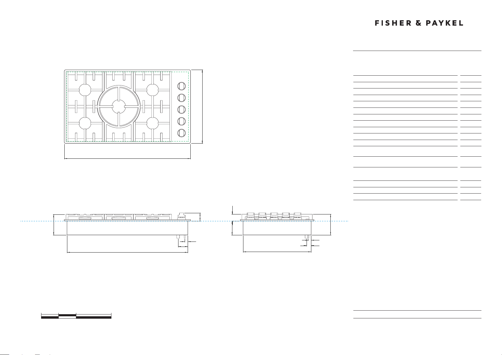
6" Professional Drop In Gas Cooktop
DATA SHEET
Model no:
CDV2-365
(refer page 3 for metric measurements)
Product Dimensions in
A Height of chassis (below top of counter)
B Overall height of product (bottom of chassis to top of grates)
D
21"
36"
C
C Overall width of cooktop
D Overall depth of cooktop
E Height from countertop datum to top of cooking surface
F Height from countertop datum to top of dials
G Width of chassis
H Depth of chassis
I Distance from right edge of chassis to center line of gas inlet
J Distance from rear edge of chassis to center line of gas inlet
K Distance from right edge of chassis to center line of
powercord
L Distance from rear edge of chassis to center line of
powercord
PLAN VIEW
Cutout Dimensions
Overall width of cutout *
Overall depth of cutout *
E
* Note cutout position is centred to the cooktop width and depth.
f
B
A
4"
B
in
k
i
g
FRONT VIEW
0 5 10 20
inches
PROFILE VIEW
h
l
j
INDICATES PRODUCT DATUM -------------------------------------------
INDICATES CUTOUT -------------------------------------------------------
DATE: 24.04.2018
IMPORTANT: Throughout this guide, dimensions may vary by ±2mm (1/16'').
Read the installation guide for detailed information on installing the product.
For full installation instructions and specifications visit fisherpaykel.com
Page 2
MINIMUM CLEARANCE:
36"
18"
12"
7"
36"
30"
13"
120 VAC, 60Hz
15 amp circuit
1/2” NPT Minimum 5/8” dia. flex line
Supply Pressure: 6” to 9” W.C.
1/2” NPT Minimum 5/8” dia. flex line
11” to 14” W.C.
5"
18"
C
NEAREST VERTICAL
COMBUSTIBLE SURFACE
DATUM :
TOP OF COUNTERTOP
MINIMUM CLEARANCE:
D
REAR VERTICAL
COMBUSTIBLE SURFACE
PLAN VIEW
MINIMUM CLEARANCE:
C
NEAREST VERTICAL
COMBUSTIBLE SURFACE
MINIMUM CLEARANCE:
E
COMBUSTIBLE SURFACE
MINIMUM CLEARANCE:
E
NON-COMBUSTIBLE SURFACE
MAXIMUM OVERALL DEPTH
F
OF OVERHEAD CABINETRY
MINIMUM CLEARANCE:
B
ADJACENT OVERHEAD CABINET
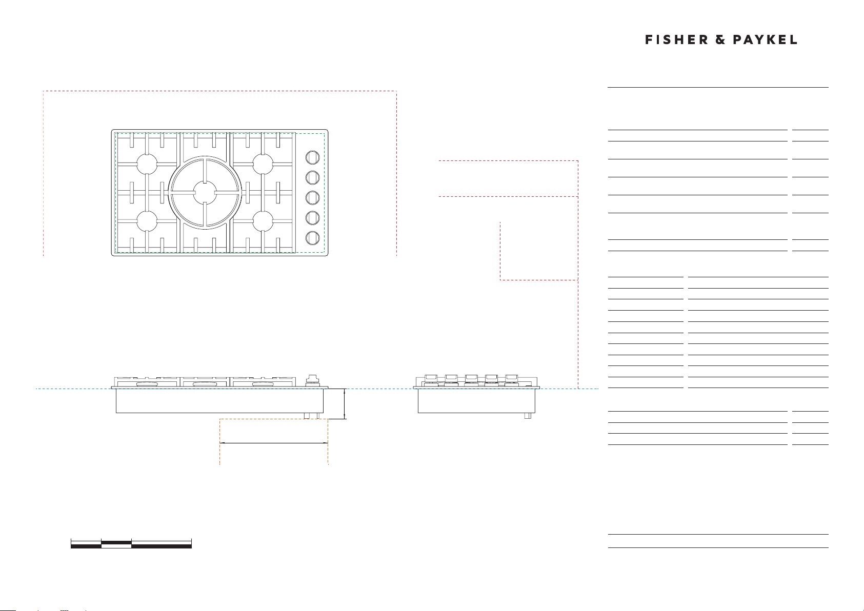
6" Professional Drop In Gas Cooktop
DATA SHEET
Model no:
CDV2-365
(refer page 4 for metric measurements)
Clearance Dimensions in
A Minimum width of ventilation hood installed above cooktop
– not shown*
B Minimum vertical distance between countertop and cabinet
extending above counter
C Minimum clearance from left and right edge of cutout to
nearest vertical combustible surface
D Minimum clearance from rear edge of cutout to nearest
combustible surface
E Minimum clearance from cooking surface to:
– combustible surface centered above the cooking surface
– non-combustible surface centered above the cooking surface
F Maximum overall depth of overhead cabinetry
Specifications
Electrical
Supply
Service
Gas – Natural
Connection
Supply Pressure
Gas – LP
Connection
Supply Pressure
0 5 10 20
FRONT VIEW
inches
f
Location of Electrical and Gas Supply in
f Distance from benchtop to electrical and gas supply area
G Width of electrical and gas supply area
g
PROFILE VIEW
INDICATES PRODUCT DATUM -------------------------------------------
INDICATES CUTOUT -------------------------------------------------------
INDICATES CLEARANCES ------------------------------------------------
INDICATES GAS AND ELCTRICAL SUPPLY AREA --------------------
DATE: 24.04.2018
IMPORTANT: Throughout this guide, dimensions may vary by ±2mm (1/16'').
Read the installation guide for detailed information on installing the product.
For full installation instructions and specifications visit fisherpaykel.com
Page 3

DATUM :
102
150
915
534
49
58
874
493
70
33
22
21
883
502
TOP OF COUNTERTOP
6" Professional Drop In Gas Cooktop
DATA SHEET
Model no:
CDV2-365
(refer page 1 for imperial measurements)
Product Dimensions mm
A Height of chassis (below top of counter)
B Overall height of product (bottom of chassis to top of grates)
D
534
915
C
C Overall width of cooktop
D Overall depth of cooktop
E Height from countertop datum to top of cooking surface
F Height from countertop datum to top of dials
G Width of chassis
H Depth of chassis
I Distance from right edge of chassis to centre line of gas inlet
J Distance from rear edge of chassis to centre line of gas inlet
K Distance from right edge of chassis to centre line of
powercord
L Distance from rear edge of chassis to centre line of
powercord
PLAN VIEW
Cutout Dimensions
Overall width of cutout *
Overall depth of cutout *
E
* Note cutout position is centred to the cooktop width and depth.
f
B
A
102
B
mm
k
i
g
FRONT VIEW
0 100 200 400
millimetres
PROFILE VIEW
h
l
j
INDICATES PRODUCT DATUM -------------------------------------------
INDICATES CUTOUT -------------------------------------------------------
DATE: 24.04.2018
IMPORTANT: Throughout this guide, dimensions may vary by ±2mm (1/16'').
Read the installation guide for detailed information on installing the product.
For full installation instructions and specifications visit fisherpaykel.com
Page 4

MINIMUM CLEARANCE:
915
457
305
178
915
762
330
120 VAC, 60Hz
15 amp circuit
1/2” NPT Minimum 5/8” dia. flex line
Supply Pressure: 6” to 9” W.C.
1/2” NPT Minimum 5/8” dia. flex line
11” to 14” W.C.
127
457
C
NEAREST VERTICAL
COMBUSTIBLE SURFACE
DATUM :
TOP OF COUNTERTOP
MINIMUM CLEARANCE:
D
REAR VERTICAL
COMBUSTIBLE SURFACE
PLAN VIEW
MINIMUM CLEARANCE:
C
NEAREST VERTICAL
COMBUSTIBLE SURFACE
MINIMUM CLEARANCE:
E
COMBUSTIBLE SURFACE
MINIMUM CLEARANCE:
E
NON-COMBUSTIBLE SURFACE
MAXIMUM OVERALL DEPTH
F
OF OVERHEAD CABINETRY
MINIMUM CLEARANCE:
B
ADJACENT OVERHEAD CABINET
6" Professional Drop In Gas Cooktop
DATA SHEET
Model no:
CDV2-365
(refer page 2 for imperial measurements)
Clearance Dimensions mm
A Minimum width of ventilation hood installed above cooktop
– not shown*
B Minimum vertical distance between countertop and cabinet
extending above counter
C Minimum clearance from left and right edge of cutout to
nearest vertical combustible surface
D Minimum clearance from rear edge of cutout to nearest
combustible surface
E Minimum clearance from cooking surface to:
– combustible surface centered above the cooking surface
– non-combustible surface centered above the cooking surface
F Maximum overall depth of overhead cabinetry
Specifications
Electrical
Supply
Service
Gas – Natural
Connection
Supply Pressure
Gas – LP
Connection
Supply Pressure
0 100 200 400
FRONT VIEW
millimetres
f
Location of Electrical and Gas Supply mm
f Distance from benchtop to electrical and gas supply area
G Width of electrical and gas supply area
g
PROFILE VIEW
INDICATES PRODUCT DATUM -------------------------------------------
INDICATES CUTOUT -------------------------------------------------------
INDICATES CLEARANCES ------------------------------------------------
INDICATES GAS AND ELCTRICAL SUPPLY AREA --------------------
DATE: 24.04.2018
IMPORTANT: Throughout this guide, dimensions may vary by ±2mm (1/16'').
Read the installation guide for detailed information on installing the product.
For full installation instructions and specifications visit fisherpaykel.com
 Loading...