

Fisher & Paykel BGCV21248, BGRV21236, BGRV23030HC, BGCV21230, BGCV21236 Installation manual
...Page 1

INSTALLATION INSTRUCTIONS
Backguard for
Professional Ranges
BGRV2 models
US CA
www.dcsappliances.com
591091A 04.16
Page 2

1 SAFETY AND WARNINGS
!
WARNING!
Cut Hazard
Take care - panel edges are sharp.
Failure to use caution could result in injury or cuts.
IMPORTANT SAFETY INSTRUCTIONS!
●
Save these instructions for the local inspectors use.
●
To avoid hazard, follow these instructions carefully before installing or using this
product.
●
Please make this information available to the person installing the product - doing so
could reduce your installation costs.
●
If the installation requires alterations to the domestic electrical system, call a qualified
electrician. The electrician should also check that the socket cable section is suitable
for the electricity drawn by the range.
2 UNPACKING AND PARTS SUPPLIED
●
Service should only be done by authorized technicians. Technicians must disconnect the
power supply before servicing this appliance.
●
Installation must comply with your local building and electricity regulations.
●
Improper installation, adjustment alteration, service or maintenance can cause property
damage, injury or death. Read the installation, operating and maintenance instructions
thoroughly.
●
DO NOT obstruct the flow of combustion or ventilation air to the accompanying appliance.
Be sure a fresh air supply is available.
●
California Proposition 65 - The burning of gas cooking fuel generates some by-products which
are known by the State of California to cause cancer or reproductive harm. California law
requires businesses to warn customers of potential exposure to such substances. To minimize
exposure to these substances, always operate this unit according to the manufacturer’s
instructions and provide good ventilation to the room when cooking with gas.
●
Check local building codes for the proper method of installation. Local codes vary.
Installation, electrical connections, and grounding must comply with all applicable codes. In
the absence of local codes, the range should be installed in accordance with the latest edition
of National Fuel Gas Code ANSI Z223.1 and National Electrical Code ANSI / NFPA 70.
●
Do not place items of interest to children on racks or appliance. Children could be seriously
injured if they should climb onto or into the appliance to reach these items.
●
Do not place combustible material (paper, cloth, plastic, etc.) on the rack.
WALL MOUNT HIGH BACKGUARD
LOW SHELF Models
Low Shelf Rack & Handle Kit
30” & 36” Models (x2 Racks)
48” Models (x3 Racks)
Unpacking and handling
●
Inspect the backguard and racks to verify that there is no shipping
damage. If any damage is detected, call the shipper and initiate a
damage claim. DCS by Fisher & Paykel is not responsible for shipping
damage.
●
DO NOT discard any packing material (box, pallet, straps) until the
unit has been inspected.
●
Range Backguard
(model specific) (1)
WALL MOUNT HIGH BACKGUARD
HIGH SHELF Models
Remove the outer carton and any packing material and dispose
responsibly.
High Shelf Rack & Handle Kit
30” & 36” Models (x2 Racks)
48” Models (x3 Racks)
Angled Trim
IMPORTANT!
SAVE THESE INSTRUCTIONS
The models shown in this installation guide may not be available in all markets and are subject to change at any time. For current details about model and specification availability in your country, please go to our
website www.dcsappliances.com or contact your local DCS by Fisher & Paykel dealer.
2
Page 3
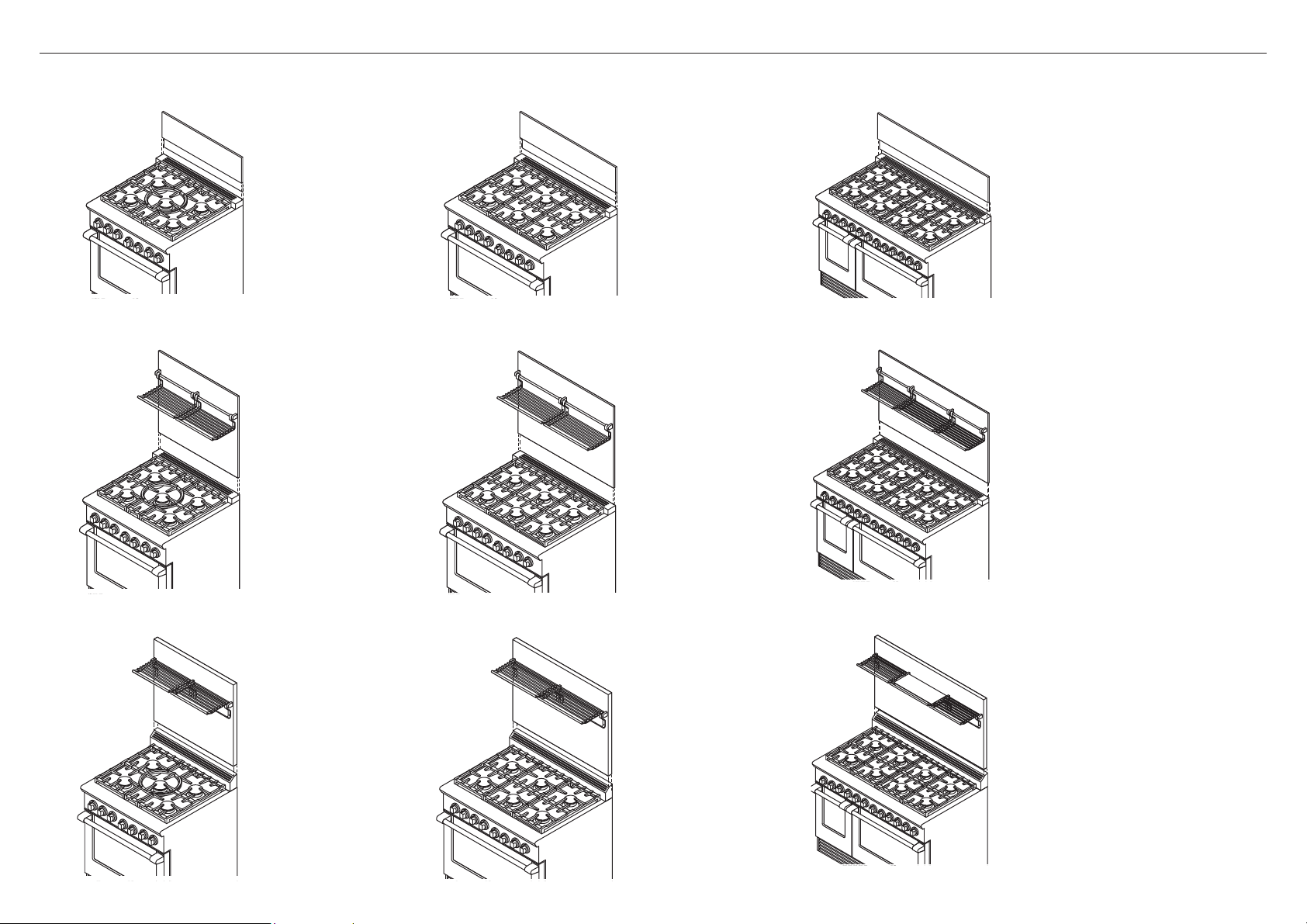
RANGE MOUNT LOW BACKGUARD
BGRV2-1230 BGRV2-1236 BGRV2-1248
WALL MOUNT HIGH BACKGUARD LOW SHELF
3 MODEL IDENTIFICATION
BGRV2-3030
WALL MOUNT HIGH BACKGUARD HIGH SHELF AND ANGLED VENT TRIM
BGRV2-3030H
BGRV2-3036
BGRV2-3036H
BGRV2-3048
BGRV2-3048H
3
Page 4
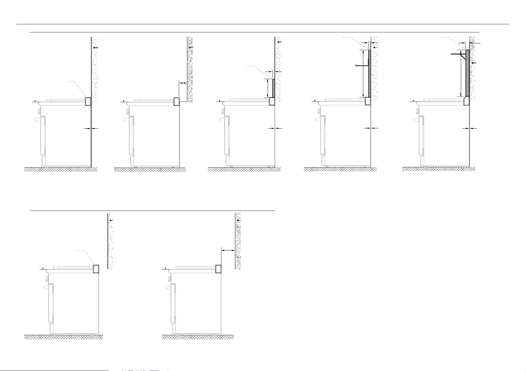
4 INSTALLATION SCENARIOS AND USE OF BACKGUARDS
WALL INSTALLATION
Vent Trim
cooking
surface
0” Clearance
scenario 1
NO BACKGUARD USED
Integral Flat Vent Trim or
Angled Flat Vent Trim (
(supplied with range)
ISLAND INSTALLATION
RGCV2-305 models only)
Non-combustible
surface*
(required)
cooking
surface
scenario 2
NO BACKGUARD USED
Integral Flat Vent Trim or
Angled Flat Vent Trim (
(supplied with range)
Min. 6” (152mm)
Clearance
RGCV2-305 models only)
Combustible
Surface
Range Mount
Low Backguard
cooking
surface
10 3/8”
(263mm)
1/2”
(13mm)
0” Clearance
scenario 3 scenario 4
RANGE MOUNT LOW BACKGUARD
(purchased separately)
Wall Mount
cooking
surface
High Backguard
Low Shelf
(720mm)
28 3/8”
Non-combustible
surface*
(required)
0” Clearance
WALL MOUNT HIGH BACKGUARD LOW SHELF
(purchased separately)
1/2”
(13mm)
Non-combustible
surface*
(required)
Wall Mount
High Backguard
High Shelf
26 1/2”
(673mm)
cooking
surface
Angled Vent Trim
(required)
0” Clearance
scenario 5
WALL MOUNT HIGH BACKGUARD
HIGH SHELF AND ANGLED VENT TRIM KIT
(purchased separately)
1 5/16”
(33mm)
Non-combustible
surface*
or
Combustible
surface
Non-Combustible
Surface*
Vent Trim
cooking
surface
scenario 6 scenario 7
NO BACKGUARD USED
Integral Flat Vent Trim or Angled Flat Vent Trim (RGCV2-305 models only)
(supplied with range)
4
Combustible
Surface
Min. 6” (152mm)
Clearance
cooking
surface
NO BACKGUARD USED
Integral Flat Vent Trim or Angled Flat Vent Trim (RGCV2-305 models only)
(supplied with range)
Page 5

4 INSTALLATION SCENARIOS AND USE OF BACKGUARDS
Important notes
●
All ranges come fitted standard with with either an Integral Flat Vent Trim or an Angled Vent Trim (RGCV2-305 models only)
●
There are three different backguards available for purchase:
●
Range Mount Low Backguard
●
Wall Mount High Backguard with Low Shelf
●
Wall Mount High Backguard with High Shelf, also supplied with an Angled Vent Trim.
●
For installations against non-combustible* surfaces only, you may install the range without a backguard or choose any of the three backguards.
●
For installations close to combustible surfaces (above the cooking surface), without a backguard, there must be a minimum 6” (152mm) clearance
(see Scenario 2 or 7 opposite)
●
For installations immediately against combustible surfaces (above the cooking surface), you must purchase and fit the Wall Mount High Backguard
High Shelf and Angled Vent Trim (see Scenario 5 opposite)
●
The cooking surface must sit flush or above the adjacent countertop level.
* Non-combustible surfaces:
as defined in ‘National Fuel Gas Code’ (ANSI Z223.1, Current Edition). Clearances from non-combustible materials
are not part of the ANSI Z21.1 scope and are not certified by UL. Clearances of less than 6” (152mm) must be
approved by the local codes and/or by the local authority having jurisdiction.
BACKGUARD MODEL NUMBERS
WALL
MOUNT HIGH
BACKGUARD
LOW SHELF
RANGE
RANGE
MOUNT LOW
BACKGUARD
30” models BGRV2-1230 BGRV2-3030 BGRV2-3030H 29 7/8” (759mm)
36” models BGRV2-1236 BGRV2-3036 BGRV2-3036H 35 7/8” (911mm)
48” models BGRV2-1248 BGRV2-3048 BGRV2-3048H 47 7/8” (1216mm)
WALL
MOUNT HIGH
BACKGUARD
HIGH SHELF
BACKGUARD
WIDTH
Note: For more information on Backguard installation, refer to the separate instructions provided with your backguard.
Backguard Installation Instructions can also be downloaded from our website, www.dcsappliances.com
5
Page 6
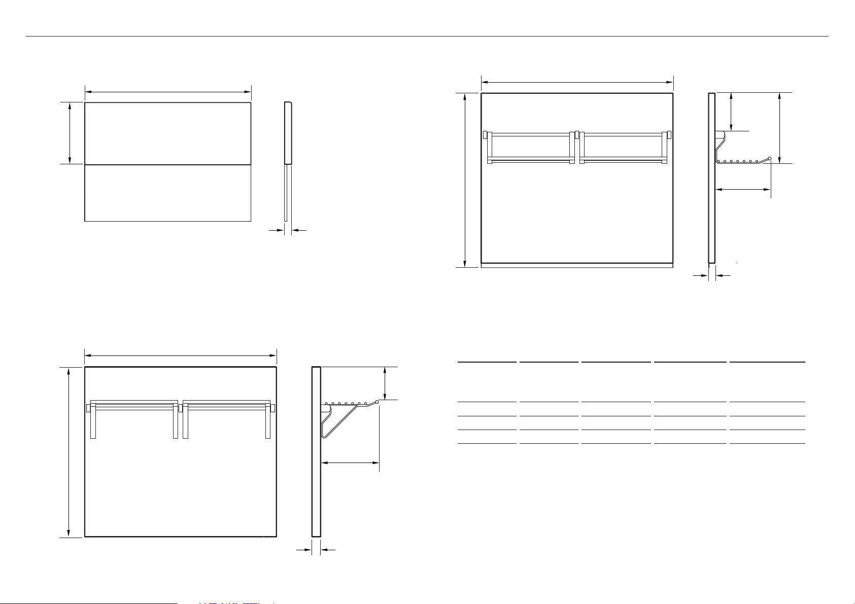
5 PRODUCT DIMENSIONS
29 1/8”
(740mm)
5 7/8”
(150mm)
8 13/16”
(224mm)
WIDTH
1/2”
(13mm)
10 15/16”
(278mm)
26 1/2”
(673mm)
WIDTH
1 5/16”
(33mm)
5 3/8”
(136mm)
9 1/16”
(230mm)
10 3/8”
(263mm)
WIDTH
1/2”
(13mm)
RANGE MOUNT LOW BACKGUARD
FRONT
PROFILE
WALL MOUNT HIGH BACKGUARD HIGH SHELF
WALL MOUNT HIGH BACKGUARD LOW SHELF
FRONT
PROFILE
6
FRONT
PROFILE
SUITABLE
RANGE
30” models BGRV2-1230 BGRV2-3030 BGRV2-3030H 29 7/8” (759mm)
36” models BGRV2-1236 BGRV2-3036 BGRV2-3036H 35 7/8” (911mm)
48” models BGRV2-1248 BGRV2-3048 BGRV2-3048H 47 7/8” (1216mm)
RANGE
MOUNT LOW
BACKGUARD
WALL
MOUNT HIGH
BACKGUARD
LOW SHELF
WALL
MOUNT HIGH
BACKGUARD
HIGH SHELF
BACKGUARD
WIDTH
Page 7
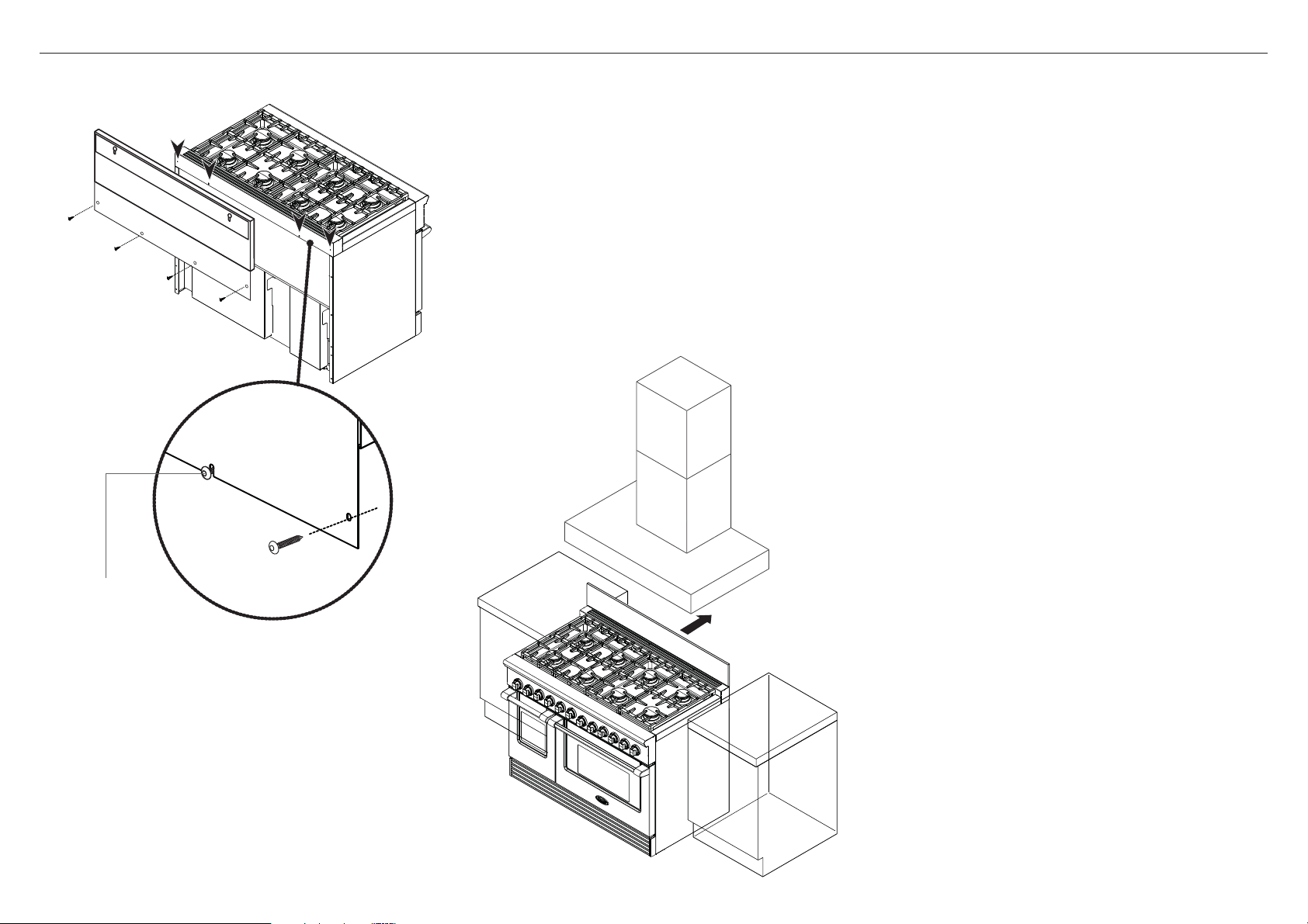
6-A RANGE MOUNT LOW BACKGUARD - ASSEMBLY
1
Attach low backguard to the rear of the range
1 Align the backguard with the range, so that it
rests on the vent trim.
2 Fasten the bottom of the backguard to the rear
of the range using all the screws provided, as
shown.
The two center screws come already attached to
the range for your convenience.
Finally position range
3 Push the range into position.
Follow the rest of the instructions shown in the
range installation instructions.
2
Center screw
These screws
come pre-attached to
rear of range
3
7
Page 8

6-B WALL MOUNT HIGH BACKGUARD WITH LOW SHELF - ASSEMBLY
1
VENT HOOD
BACKGUARD
RANGE
2
End
cap
3
Center
stanchion
#10 machine
Rod
screws
End
cap
1 Recommended installation order:
1] VENT HOOD
2] BACKGUARD
3] RANGE
Locate and Mark the two mounting screw locations
2 Use the diagram below depending on your
particular model.
Attach rod etc
3 Attach rod, end caps and center stanchion to
backguard with #10 machine screws supplied.
continued over...
B
C
Top of Vent Trim
Mounting screw locations
A
B
C
30” MODELS 36” MODELS 48” MODELS
inches (mm) inches (mm) inches (mm)
6 15/16” (176) 1 15/16” (50) 7 15/16” (202)
16” (406) 32” (813) 32” (813)
26 9/16” (675) 26 9/16” (675) 26 9/16” (675)
Mounting
Hole
location
Mounting
Hole
location
A
8
Page 9

4
Upper
mounting
screws
6-B WALL MOUNT HIGH BACKGUARD WITH LOW SHELF - ASSEMBLY
1/16”
(2mm)
6
5
Ensure backguard is
snug tight with the
bottom of the vent
hood and wall
Rear mounting slots
4 Use the marked holes to locate the upper
5 Place the backguard onto the screws by lining
6 Push backguard up and adjust until it sits flush
Ensure the backguard is tight on the wall and is
7 Once the backguard is in position, mark, drill and
8 Attach the racks to rod (racks may vary).
9 Push the range into position so that the
Follow the rest of the instructions shown in the
Mount Backguard to wall
mounting screw locations on the wall.
Pre-drill and install flange head screws (not
supplied), leaving 1/16” (1mm) between the
screw head and wall.
up the screw heads with the rear mounting slots.
with the bottom of the vent hood.
not loose. You may need to adjust the depth of
the mounting screws to achieve this.
install the lower mounting screws at the bottom
of the backguard.
Attach racks
Finally position range
backguard sits flush with the top of the range
vent trim.
range installation instructions.
8
Racks
Lower
mounting
screws
IMPORTANT!
The back section must be securely fastened to
the wall. Failure to do so could cause damage
or personal injury if the Backguard was to pull
free from wall when racks are loaded. The
maximum weight placed on each rack should
be 10lbs.
7
9
9
Page 10

6-C WALL MOUNT HIGH BACKGUARD WITH HIGH SHELF - REPLACE THE VENT TRIM
Flat Vent Trim
1
4
2
Remove the flat vent trim
1 If using the high backguard with high shelf, you must
install the angle trim (supplied) first.
First, remove the two screws at the back of the trim
as shown.
2 Carefully lift off the flat vent trim and also the pan
supports/griddle/grill frame etc.
IMPORTANT!
Be careful not to touch any exposed electrical
wiring or internals at this stage.
Install the angle vent trim
3 Paying particular attention to the metal tabs around
the opening of the range, carefully place the angle
trim down over the rear trim of the range.
4 The angle trim must fit properly over the spill guards
and hob edge.
5 Refit the two screws into the rear trim as shown.
10
3
5
Page 11

6-C WALL MOUNT HIGH BACKGUARD WITH HIGH SHELF - ASSEMBLY
End
cap
1
Ta b
Front section
3
Center
stanchion
Hole
Rod
End
cap
VENT HOOD
BACKGUARD
RANGE
Bend down
approx.
3/16” (5mm)
4
#10 machine
screws
Back section
Choose slots
Racks
6
2
30” MODELS = 16” (406mm)
36/48” MODELS = 32” (813mm)
7
1/4”
(6mm)
1 Recommended installation order:
1] VENT HOOD
2] BACKGUARD
3] RANGE
Locate and Mark the mounting screw locations for
backguard back section
2 After unpacking all backguard parts, position the
back section so that it’s 1/4” (6mm) and centered
above the Vent Trim attached to the range. Secure
back section to wall with the appropriate fasteners
(not supplied) to anchors or wood stud. The slots
in the back section may be used to adjust spacing
between range vent trim and backguard for a flush
fit.
Attach rod etc to front section
3 Attach rod, end caps and center stanchion to front
section of backguard with #10 machine screws
supplied.
Secure front section to back section
4 Bend wedge-shaped tabs down on top of the front
section approximately 3/16” (5mm).
5 Secure front section of backguard to back section
with #8 self-tapping sheet metal screws supplied.
When mounting the front section, ensure that these
tabs engage the mating holes in the top of the rear
section.
Attach racks
6 Attach the racks to rod (racks may vary).
Finally position range
7 Push the range into position so that the backguard
sits flush with the top of the range vent trim.
Follow the rest of the instructions shown in the range
installation instructions.
5
Front section
Ta b
Hole
#8
Selftapping
sheet metal
screws
Back section
IMPORTANT!
The back section must be securely fastened to
the wall. Failure to do so could cause damage or
personal injury if the Backguard was to pull free
from wall when racks are loaded. The maximum
weight placed on each rack should be 10lbs.
11
Page 12

7 FINAL CHECKLIST
TO BE COMPLETED BY THE INSTALLER
GENERAL
Correct and suitable placement of the appliance and backguard.
Specified clearances maintained to cabinet surfaces.
Specified clearances maintained to either combustible or non-combustible surfaces.
Backguard centered under hood and level - front to back, side to side and is securely fastened to the appliance
(Range Mount Low Backguard only) or to the wall.
All packaging material and tie straps removed.
Angle trim (Wall Mount High Backguard High Shelf only) is correctly placed over the rear trim of the trim and
fits properly over the spill guards and hob edge.
Ensure all racks are fitted and securely in place
Complete and keep for safe reference:
Model
Serial No.
Purchase Date
Purchaser
Dealer Address
Installer’s Name
Installer’s Signature
Installation Company
Installation Date
12
Copyright © Fisher & Paykel Appliances 2016. All rights reserved.
The product specifications in this booklet apply to the specific products
and models described at the date of issue. Under our policy of continuous
product improvement, these specifications may change at any time. You
should therefore check with your Dealer to ensure this booklet correctly
describes the product currently available.
Page 13

13
Page 14

INSTALLATION INSTRUCTIONS
Backguard for
Professional Cooktops
BGCV2 models
US CA
www.dcsappliances.com
591091A 04.16
Page 15

1 SAFETY AND WARNINGS
!
WARNING!
Cut Hazard
Take care - panel edges are sharp.
Failure to use caution could result in injury or cuts.
IMPORTANT SAFETY INSTRUCTIONS!
●
Save these instructions for the local inspectors use.
●
To avoid hazard, follow these instructions carefully before installing or using this
product.
●
Please make this information available to the person installing the product - doing so
could reduce your installation costs.
●
If the installation requires alterations to the domestic electrical system, call a qualified
electrician. The electrician should also check that the socket cable section is suitable
for the electricity drawn by the cooktop.
2 UNPACKING AND PARTS SUPPLIED
●
Service should only be done by authorized technicians. Technicians must disconnect the
power supply before servicing this appliance.
●
Installation must comply with your local building and electricity regulations.
●
Improper installation, adjustment alteration, service or maintenance can cause property
damage, injury or death. Read the installation, operating and maintenance instructions
thoroughly.
●
DO NOT obstruct the flow of combustion or ventilation air to the accompanying appliance.
Be sure a fresh air supply is available.
●
California Proposition 65 - The burning of gas cooking fuel generates some by-products which
are known by the State of California to cause cancer or reproductive harm. California law
requires businesses to warn customers of potential exposure to such substances. To minimize
exposure to these substances, always operate this unit according to the manufacturer’s
instructions and provide good ventilation to the room when cooking with gas.
●
Check local building codes for the proper method of installation. Local codes vary.
Installation, electrical connections, and grounding must comply with all applicable codes. In
the absence of local codes, the range should be installed in accordance with the latest edition
of National Fuel Gas Code ANSI Z223.1 and National Electrical Code ANSI / NFPA 70.
●
Do not place items of interest to children on racks or appliance. Children could be seriously
injured if they should climb onto or into the appliance to reach these items.
●
Do not place combustible material (paper, cloth, plastic, etc.) on the rack.
WALL MOUNT HIGH BACKGUARD
LOW SHELF Models
Low Shelf Rack & Handle Kit
30” & 36” Models (x2 Racks)
48” Models (x3 Racks)
Unpacking and handling
●
Inspect the backguard and racks to verify that there is no shipping
damage. If any damage is detected, call the shipper and initiate a
damage claim. DCS by Fisher & Paykel is not responsible for shipping
damage.
●
DO NOT discard any packing material (box, pallet, straps) until the
unit has been inspected.
●
Cooktop Backguard
(model specific) (1)
WALL MOUNT HIGH BACKGUARD
HIGH SHELF Models
High Shelf Rack & Handle Kit
Remove the outer carton and any packing material and dispose
responsibly.
30” & 36” Models (x2 Racks)
48” Models (x3 Racks)
IMPORTANT!
SAVE THESE INSTRUCTIONS
The models shown in this installation guide may not be available in all markets and are subject to change at any time. For current details about model and specification availability in your country, please go to our
website www.dcsappliances.com or contact your local DCS by Fisher & Paykel dealer.
2
Page 16

WALL MOUNT LOW BACKGUARD
BGCV2-1230 BGCV2-1236 BGCV2-1248
WALL MOUNT HIGH BACKGUARD LOW SHELF
3 MODEL IDENTIFICATION
BGCV2-3030
WALL MOUNT HIGH BACKGUARD HIGH SHELF
BGCV2-3030H
BGCV2-3036
BGCV2-3036H
BGCV2-3048
BGCV2-3048H
3
Page 17

WALL INSTALLATION
cooking
surface
Non-combustible
surface*
(required)
cooking
surface
4 COOKTOP INSTALLATION SCENARIOS AND USE OF BACKGUARDS
15/16”
(23mm)
Non-combustible
surface*
(required)
Min. 6” (152mm)
Clearance
Combustible
Surface
cooking
surface
Wall Mount
Low Backguard
12”
(305mm)
Non-combustible
surface*
(required)
15/16”
(23mm)
cooking
surface
Wall Mount
High Backguard
Low Shelf
(762mm)
30”
Wall Mount
High Backguard
High Shelf
cooking
surface
30”
(762mm)
15/16”
(23mm)
Non-combustible
surface*
or
Combustible
surface
Min. 0” Clearance
Cabinetry Cabinetry Cabinetry Cabinetry Cabinetry
scenario 1
NO BACKGUARD USED
ISLAND INSTALLATION
cooking
surface
scenario 2
NO BACKGUARD USED
Non-Combustible
Surface*
cooking
surface
scenario 3 scenario 4
WALL MOUNT LOW BACKGUARD
(purchased separately)
Combustible
Surface
Min. 6” (152mm)
Clearance
Min. 0” Clearance
Min. 0” Clearance
WALL MOUNT HIGH BACKGUARD LOW SHELF
(purchased separately)
0” Clearance
scenario 5
WALL MOUNT HIGH BACKGUARD HIGH SHELF
(purchased separately)
Cabinetry
scenario 6 scenario 7
NO BACKGUARD USED
4
Cabinetry
NO BACKGUARD USED
Page 18

4 COOKTOP INSTALLATION SCENARIOS AND USE OF BACKGUARDS
Important notes
●
There are three different backguards available for purchase:
●
Wall Mount Low Backguard
●
Wall Mount High Backguard with Low Shelf
●
Wall Mount High Backguard with High Shelf.
●
For installations against non-combustible* surfaces only, you may install the cooktop without a backguard or choose any of the three backguards.
●
For installations close to combustible surfaces (above the cooking surface), without a backguard, there must be a minimum 6” (152mm) clearance (see Scenario 2 or 7 opposite)
●
For installations immediately against combustible surfaces (above the cooking surface), you must purchase the Wall Mount High Backguard High Shelf (scenario 5 opposite).
●
The cooking surface must sit flush or above the adjacent countertop level.
* Non-combustible surfaces:
as defined in ‘National Fuel Gas Code’ (ANSI Z223.1, Current Edition). Clearances from non-combustible materials
are not part of the ANSI Z21.1 scope and are not certified by UL. Clearances of less than 6” (152mm) must be
approved by the local codes and/or by the local authority having jurisdiction.
BACKGUARD MODEL NUMBERS
COOKTOP
WALL
MOUNT LOW
BACKGUARD
WALL
MOUNT HIGH
BACKGUARD
LOW SHELF
WALL
MOUNT HIGH
BACKGUARD
HIGH SHELF
BACKGUARD
WIDTH
30” models BGCV2-1230 BGCV2-3030 BGCV2-3030H 29 7/8” (759mm)
36” models BGCV2-1236 BGCV2-3036 BGCV2-3036H 35 7/8” (911mm)
48” models BGCV2-1248 BGCV2-3048 BGCV2-3048H 47 7/8” (1216mm)
Note: Backguard Installation Instructions can also be downloaded from our website, www.dcsappliances.com
5
Page 19

5 PRODUCT DIMENSIONS
30”
(762mm)
5 7/8”
(150mm)
8 13/16”
(224mm)
WIDTH
15/16”
(23mm)
10 15/16”
(278mm)
30”
(762mm)
WIDTH
15/16”
(23mm)
5 3/8”
(136mm)
9 1/16”
(230mm)
12"
(305mm)
WIDTH
15/16"
(23mm)
WALL MOUNT LOW BACKGUARD
FRONT
WALL MOUNT HIGH BACKGUARD HIGH SHELF
WALL MOUNT HIGH BACKGUARD LOW SHELF
PROFILE
FRONT
PROFILE
6
FRONT
PROFILE
SUITABLE
RANGE
30” models BGCV2-1230 BGCV2-3030 BGCV2-3030H 29 7/8” (759mm)
36” models BGCV2-1236 BGCV2-3036 BGCV2-3036H 35 7/8” (911mm)
48” models BGCV2-1248 BGCV2-3048 BGCV2-3048H 47 7/8” (1216mm)
WALL
MOUNT LOW
BACKGUARD
WALL
MOUNT HIGH
BACKGUARD
LOW SHELF
WALL
MOUNT HIGH
BACKGUARD
HIGH SHELF
BACKGUARD
WIDTH
Page 20

1
VENT HOOD
BACKGUARD
COOKTOP
6-A WALL MOUNT LOW BACKGUARD - ASSEMBLY
30” MODELS = 16” (406mm)
36/48” MODELS = 32” (813mm)
Use slots to
correctly position
Back section
2
Cooktop
Trim
1/4”
(6mm)
1 Recommended installation order:
1] VENT HOOD
2] BACKGUARD
3] COOKTOP
Locate and Mark the mounting screw locations for
back section
2 After unpacking all backguard parts, position the
back section so that it’s 1/4” (6mm) and centered
above the cooktop trim. Secure back section to wall
with the appropriate fasteners (not supplied) to
anchors or wood stud. The slots in the back section
may be used to adjust spacing between cooktop trim
and backguard for a flush fit.
Secure front section to back section
3 Secure front section of backguard to back section
with #8 self-tapping sheet metal screws supplied.
Finally position cooktop
7 Place the cooktop into position so that the backguard
sits flush with the top of the cooktop trim.
Follow the rest of the instructions shown in the
cooktop installation instructions.
Front section
Back section
34
#8
Selftapping
sheet metal
screws
IMPORTANT!
The back section must be securely fastened to
the wall. Failure to do so could cause damage or
personal injury if the Backguard was to pull free
from wall.
7
Page 21

6-B WALL MOUNT HIGH BACKGUARD WITH LOW SHELF/HIGH SHELF - ASSEMBLY
Use slots to
correctly position
1
End
cap
Ta b
Front section
3
Center
stanchion
Hole
Rod
VENT HOOD
BACKGUARD
COOKTOP
4
End
cap
Back section
Bend down
approx.
3/16” (5mm)
#10 machine
screws
6
Racks
2
30” MODELS = 16” (406mm)
36/48” MODELS = 32” (813mm)
Cooktop
Trim
7
1/4”
(6mm)
1 Recommended installation order:
1] VENT HOOD
2] BACKGUARD
3] COOKTOP
Locate and Mark the mounting screw locations for
back section
2 After unpacking all backguard parts, position the
back section so that it’s 1/4” (6mm) and centered
above the cooktop trim. Secure back section to wall
with the appropriate fasteners (not supplied) to
anchors or wood stud. The slots in the back section
may be used to adjust spacing between cooktop trim
and backguard for a flush fit.
Attach rod etc to front section
3 Attach rod, end caps and center stanchion to front
section of backguard with #10 machine screws
supplied.
Secure front section to back section
4 Bend wedge-shaped tabs down on top of the front
section approximately 3/16” (5mm).
5 Secure front section of backguard to back section
with #8 self-tapping sheet metal screws supplied.
When mounting the front section, ensure that these
tabs engage the mating holes in the top of the rear
section.
Attach racks
6 Attach the racks to rod (racks may vary).
Finally position cooktop
7 Place the cooktop into position so that the backguard
sits flush with the top of the cooktop trim.
Follow the rest of the instructions shown in the
cooktop installation instructions.
Hole
IMPORTANT!
The back section must be securely fastened to
the wall. Failure to do so could cause damage or
personal injury if the Backguard was to pull free
from wall when racks are loaded. The maximum
weight placed on each rack should be 10lbs.
5
Front section
Ta b
#8
Selftapping
sheet metal
screws
7
Back section
8
Page 22

7 FINAL CHECKLIST
TO BE COMPLETED BY THE INSTALLER
GENERAL
Correct and suitable placement of the appliance and backguard.
Specified clearances maintained to cabinet surfaces.
Specified clearances maintained to either combustible or non-combustible surfaces.
Backguard centered under hood and level - front to back, side to side and sits flush with the top of the cooktop trim.
All packaging material and tie straps removed.
Front section of backguard is securely attached to the back section.
Wedge-shaped tabs on top of front section (Wall Mount High Backguard only) are properly engaged with corresponding
holes in top of rear section.
Ensure all racks are fitted and securely in place
Complete and keep for safe reference:
Model
Serial No.
Purchase Date
Purchaser
Dealer Address
Installer’s Name
Installer’s Signature
Installation Company
Installation Date
Copyright © Fisher & Paykel Appliances 2016. All rights reserved.
The product specifications in this booklet apply to the specific products
and models described at the date of issue. Under our policy of continuous
product improvement, these specifications may change at any time. You
should therefore check with your Dealer to ensure this booklet correctly
describes the product currently available.
9
Page 23

10
Page 24

11
 Loading...