

Page 1
Technical Documentation
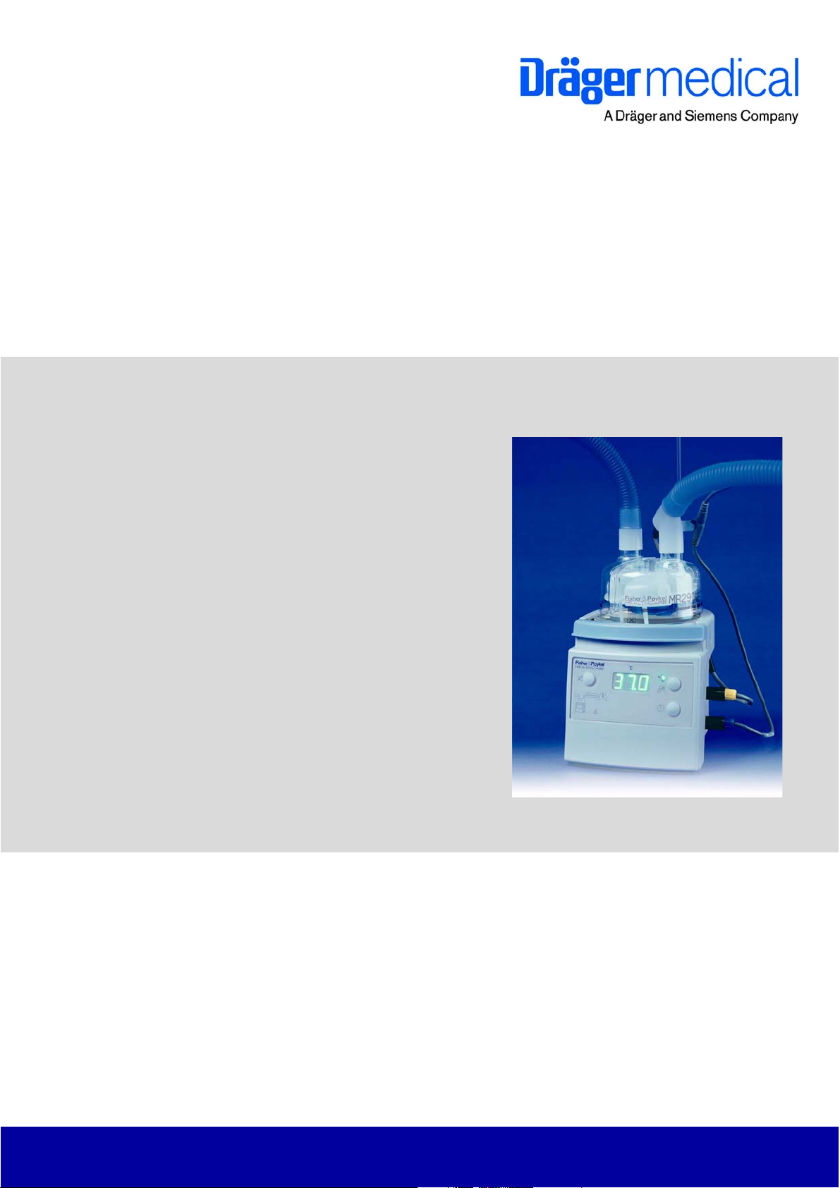
Fisher & Paykel® MR 850
Respiratory Humidifier
Revision 5.0
5697.500
9036209
Because you care
Page 2

Page 3

Contents
General
1 Symbols and Definitions 3
2 Notes 3
Function Description
1 MR 850 Respiratory Humidifier 7
1.1 Humidifier Operation .............................................................................................................. 7
1.2 Operating Modes .................................................................................................................... 8
1.2.1 Stand-by mode ......................................................................................................... 8
1.2.2 Intubated mode ........................................................................................................ 8
1.2.3 Mask mode ............................................................................................................... 8
1.3 Controls .................................................................................................................................. 9
1.3.1 On/off button ............................................................................................................. 9
1.3.2 Mode button ............................................................................................................. 9
1.3.3 Mute button .............................................................................................................. 9
1.4 Optical Indicators .................................................................................................................. 10
1.4.1 Display .................................................................................................................... 10
1.4.2 Humidity alarm (lung symbol) ................................................................................. 10
1.4.3 Warning triangle alarm ........................................................................................... 10
1.5 Setup Indicators (LEDs) ....................................................................................................... 10
1.5.1 Temperature probes ............................................................................................... 10
1.5.2 Heater wire adapter ................................................................................................ 10
K5697500IECIVZ.fm 10.05.06
1.5.3 Temperature probe connectors .............................................................................. 11
1.5.4 Humidification chamber temperature probe alarm with probe connector alarm ..... 11
1.5.5 Airway temperature probe alarm with probe connector alarm ................................ 11
1.5.6 Water out LED ........................................................................................................ 11
1.6 Operational Alarms ............................................................................................................... 11
1.6.1 Humidity alarm (lung symbol) ................................................................................. 11
All rights reserved. Copyright reserved.
I
Page 4

Contents
Annex
Parts catalog
Test List
K5697500IECIVZ.fm 10.05.06
All rights reserved. Copyright reserved.
II
Page 5

General
1
Page 6

2
Page 7

Fisher & Paykel MR 850 General
1 Symbols and Defini-
tions
WARNING
A WARNING statement provides important information about a potentially hazardous situation which, if not avoided, could result in death
or serious injury.
CAUTION
A CAUTION statement provides important information about a potentially
hazardous situation which, if not avoided, may result in minor or moderate
injury to the user or patient or in damage to the equipment or other property.
NOTE
A NOTE provides additional information intended to avoid inconvenience
during operation.
Definitions according to German standard DIN 31051:
Inspection = examination of actual condition
Maintenance = measures to maintain specified condition
Repair = measures to restore specified condition
Servicing = inspection, maintenance, and repair
2Notes
This Technical Documentation conforms to the IEC 60601-1 standard.
Read each step in every procedure thoroughly before beginning any test.
Always use the proper tools and specified test equipment. If you deviate from
the instructions and/or recommendations in this Technical Documentation,
the equipment may operate improperly or unsafely, or the equipment could be
damaged.
It is our recommendation to use only Dräger parts and supplies.
The maintenance procedures described in this Technical Documentation may
be performed by qualified service personnel only. These maintenance procedures do not replace inspections and servicing by the manufacturer.
The information in this Technical Documentation is confidential and may not
be disclosed to third parties without the prior written consent of the manufacturer.
This Technical Documentation is for the purpose of information only. Product
descriptions found in this Technical Documentation are in no way a substitute
for reading and studying the Instructions for Use/Operating Manual enclosed
with the product at the time of delivery.
All rights reserved. Copyright reserved.
Version 3.0_ Released_Printed on_10.05.06_General_Technical_Documentation.fm
5697.500
3
Page 8

General Fisher & Paykel MR 850
Know-how contained in this Technical Documentation is subject to ongoing
change through research and development and Dräger Medical reserves the
right to make changes to this Technical Documentation without notice.
NOTE
Unless otherwise stated, reference is made to laws, regulations or standards (as amended) applicable in the Federal Republic of Germany for
equipment used or serviced in Germany. Users or technicians in all other
countries must verify compliance with local laws or applicable international
standards.
Version 3.0_ Released_Printed on_10.05.06_General_Technical_Documentation.fm
All rights reserved. Copyright reserved.
4
5697.500
Page 9

Function Description
5
Page 10

6
Page 11
Fisher & Paykel MR 850 Function Description
1 MR 850 Respiratory
Humidifier
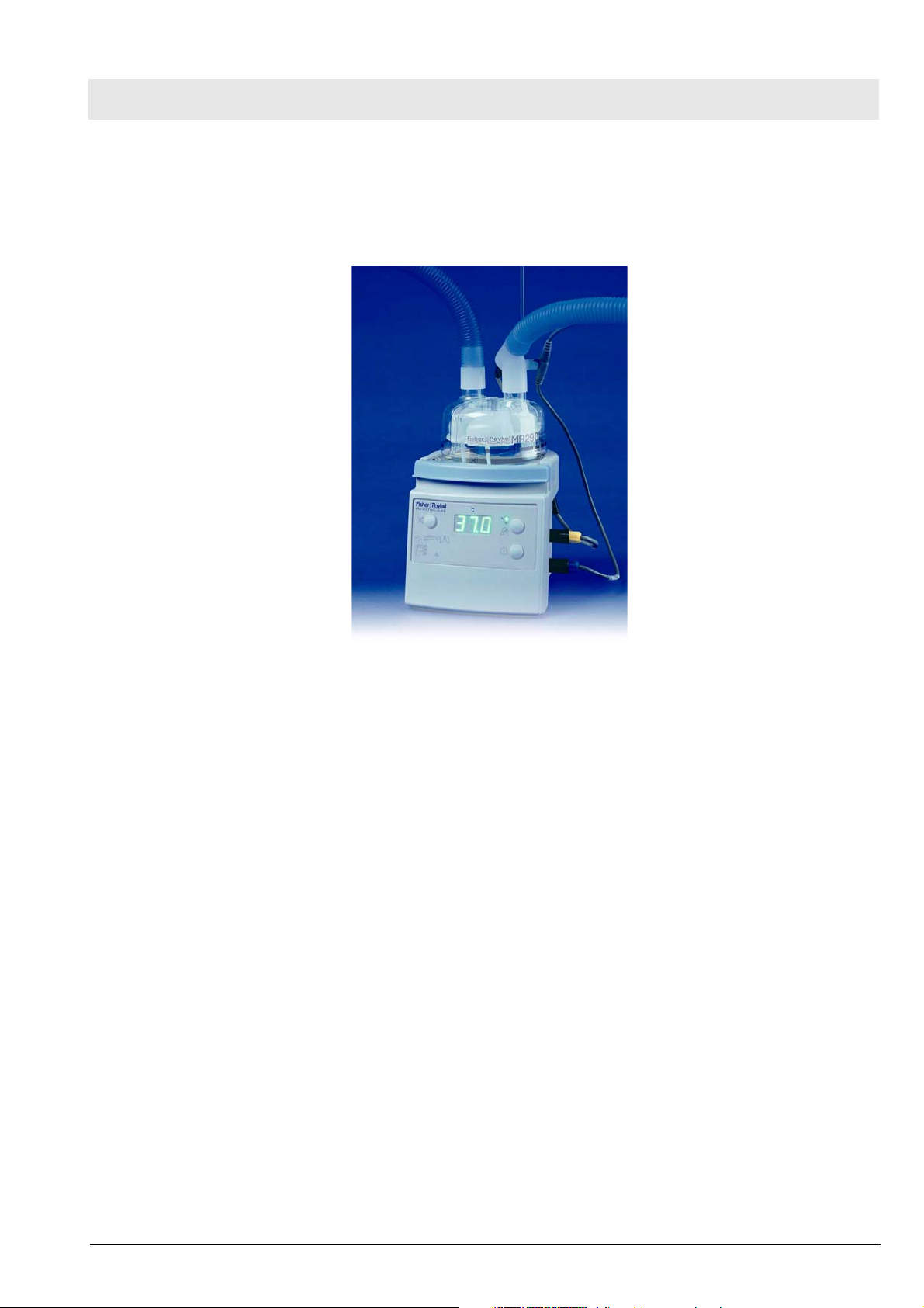
The MR 850 Respiratory humidifier is designed to add heat and moisture to
the respiratory gas delivered to the patient. The humidifier can be connected
to various ventilators. It supports CPAP ventilation, delivery of other medical
gases, intubation and mask ventilation.
Figure 1 MR 850 Respiratory Humidifier
1.1 Humidifier Operation The respiratory gas flows into the humidification chamber. A heater plate
heats the sterile, pyrogen-free water contained in the humidification chamber.
The heater plate is located below the humidification chamber. The heated
water humidifies the respiratory gas. A temperature probe at the humidification chamber outlet measures the respiratory gas temperature. The measurement signal is transmitted to a control circuitry. This control circuitry controls
the amount of power delivered to the heater plate in order to maintain the respiratory gas temperature at a constant level.
The heated and humidified respiratory gas travels through the inspiratory
limb. The inspiratory limb has a heater wire inside. A temperature probe measures the patient’s respiratory gas temperature. The opening of this temperature probe is located at the end of the inspiratory limb near the patient. The
measurement signal from the temperature probe is transmitted to a control
circuitry. This control circuitry controls the power delivered to the heater wire
in order to maintain the respiratory gas temperature at the inlet and outlet of
the inspiratory limb at a constant level. This prevents the humidity contained
in the respiratory gas from condensing in the inspiratory limb.
An expiratory limb heater wire must also be used in order to stop the patient’s
expired humidity from condensing into the expiratory limb of the breathing circuit.
For internal use only. Copyright reserved.
Version 1.2_ Released_Printed on_10.05.06_F5697500T01.fm
5697.500
7
Page 12

Function Description Fisher & Paykel MR 850
1.2 Operating Modes
1.2.1 Stand-by mode Depending on the severity of the alarm condition, the humidifier will either
enter stand-by mode or remove all power from the heating systems (heater
plate, heater wire(s)).
The humidifier will generate an audible alarm and always enter stand-by
mode if the following occurs:
– Malfunction/error during operation
– Incorrect settings
– Gas flow in breathing circuit stops
In stand-by mode the following occurs:
– Heater wire power is set to 30 %
– Heater plate temperature is limited to 60 °C
– Heater plate power is limited to 20 %
1.2.2 Intubated mode ”Intubated” is the default mode on power on of the humidifier. This mode is for
use with patients who need to be ventilated mechanically. The humidifier
delivers an optimally humidified respiratory gas of 44 mg/L to the patient. The
respiratory gas temperature is almost the same as the patient’s core temperature (37 °C).
If ambient conditions change, e.g. due to cold or drafts, the temperature can
be reduced in steps to 35 °C in order to prevent condensate buildup in the
inspiratory limb.
1.2.3 Mask mode ”Mask” mode is suitable for patients who are receiving gas via a face mask
(O2 therapy, CPAP). In this mode the patients receive respiratory gas that
has an adequate humidity level (to compensate for the unphysiologically high
gas flow rate).
Version 1.2_ Released_Printed on_10.05.06_F5697500T01.fm
For internal use only. Copyright reserved.
8
5697.500
Page 13

Fisher & Paykel MR 850 Function Description
1.3 Controls
1.3.1 On/off button If the on/off button is held down briefly, the humidifier will toggle on or off.
After power-on the humidifier starts an internal diagnostic routine (self test).
An audible signals tells the user when the self test is completed.
1.3.2 Mode button When held down for one second, the mode button toggles the humidifier
between mask mode and intubated mode.
1.3.3 Mute button The mute button silences the humidifier’s audible alarm. The muted time
depends on the alarm condition and the type of alarm.
Both the chamber temperature and then the airway temperature can be displayed by pushing and holding the mute button for 1 second. The display will
return to airway temperature after a few seconds.
For internal use only. Copyright reserved.
Version 1.2_ Released_Printed on_10.05.06_F5697500T01.fm
5697.500
9
Page 14

Function Description Fisher & Paykel MR 850
1.4 Optical Indicators
1.4.1 Display The display shows the saturation temperature of the delivered respiratory gas
in °C. Normally, it is the temperature of the humidification chamber (in intubated mode approx. 37 °C, in mask mode approx. 30 °C)
1.4.2 Humidity alarm (lung
symbol)
1.4.3 Warning triangle alarm The warning triangle indicates a serious hardware fault.
1.5 Setup Indicators
(LEDs)
1.5.1 Temperature probes These LEDs will light if the temperature probes (humidification chamber, air-
The humidifier will generate an audible and visual alarm if the temperature in
the humidification chamber is above 41 °C or the respiratory gas temperature
is above 43 °C.
The humidifier generates a visual and audible alarm if in intubated mode a
low level of humidity is being delivered to the patient for too long.
The humidity alarm may be caused by ambient conditions (cold, drafts) or
can result from too high or too low gas flow rates.
WARNING
If the warning triangle on the MR 850 Respiratory Humidifier comes
on, immediately take the humidification chamber and the breathing
circuit out of service.
The setup indicators (LEDs), placed on the lower left of the front panel, light
when the humidifier and its accessories are not set up correctly.
way) are not correctly plugged into the breathing circuit or the humidifier.
After power-on or fast changing of temperature values, the humidifier checks
whether the temperature probes are plugged in or not by first cooling down
then heating up the respiratory gas.
If the humidifier finds that either probe is not inserted into the breathing circuit, an alarm will be generated and the humidifier will enter stand-by mode.
During this alarm the humidifier will initiate a probe out test periodically, or a
test will be initiated immediately after mute has been pressed.
During periods of low or zero gas flow, the airway probe out alarm is disabled.
As soon as flow is detected however, an airway probe test is initiated.
1.5.2 Heater wire adapter The heater wired adapter indicator will light under the following conditions:
– Heater wire adapter not connected correctly
– Breathing circuit is faulty or not connected correctly
– There is an intermittent connection
– Excessive current in the heater wires (total current in all limbs greater
than 3.5 A)
The humidifier will remove power from the heating system if the heater wire
adapter alarm is active.
10
5697.500
Version 1.2_ Released_Printed on_10.05.06_F5697500T01.fm
For internal use only. Copyright reserved.
Page 15

Fisher & Paykel MR 850 Function Description
1.5.3 Temperature probe connectors
1.5.4 Humidification chamber
temperature probe alarm
with probe connector
alarm
1.5.5 Airway temperature
probe alarm with probe
connector alarm
The temperature probe LEDs will light under the following conditions:
– Temperature probes are not connected correctly to the humidifier
– Temperature probes are faulty
The humidifier checks whether the temperature probes are open or short circuited.
The humidifier checks to see if the humidification chamber temperature probe
is faulty by testing for the following conditions:
– Humidification chamber temperature is greater than 80 °C.
– Humidification chamber temperature has been greater than 50 °C for 20
minutes.
If an apparent fault is found, the humidifier will give a probe connector alarm
and the LED of the humidification chamber temperature probe will light. The
humidifier will stay in stand-by mode until the temperature at the humidification chamber temperature probe drops below 50 °C.
The humidifier checks to see if the airway temperature probe is faulty by testing for the following conditions:
– Airway temperature is greater than 80 °C.
– Airway temperature has been greater than 50 °C for 5 minutes.
If an apparent fault is found, the humidifier will give a probe connector alarm
and the LED of the airway temperature probe will light. The humidifier will
stay in stand-by mode until the temperature at the airway temperature probe
drops below 50 °C.
1.5.6 Water out LED The water out LED indicates that there is insufficient water in the humidifica-
tion chamber.
The humidifier controls the amount of power required to maintain the set
chamber temperature at a constant level.
If a lower than expected amount of power is required, the humidifier will generate a visual and audible water out alarm.
With greater changes in flow it may take 15 minutes or longer to generate a
water out alarm.
The water out alarm can be cancelled for 1 minute by pressing the mute button. If however the water out condition remains, the humidifier will re-alarm.
1.6 Operational Alarms These alarms are generated if problems occur with the operation of the
humidifier.
1.6.1 Humidity alarm (lung
symbol)
A humidity alarm will occur if the displayed temperature is too high, or if the
delivered humidity (intubated mode only) has been low for a period of time.
The humidifier will generate a visual and audible alarm if the humidification
chamber temperature exceeds 41 °C or the airway chamber exceeds 43 °C.
If these high temperature alarms occur, the humidifier will immediately shut
down the heater wire and the heater plate.
For internal use only. Copyright reserved.
Version 1.2_ Released_Printed on_10.05.06_F5697500T01.fm
5697.500
11
Page 16
Function Description Fisher & Paykel MR 850
Low humidity warning and alarm
The low humidity warning and alarm are disabled during warm-up and no flow
conditions.
The lung symbol lights when a low level of humidity is being delivered to the
patient. The audible alarm alerts the user that a low level of humidity has
been delivered to the patient for too long.
The humidification chamber temperature probe controls the humidity low
warning or alarm.
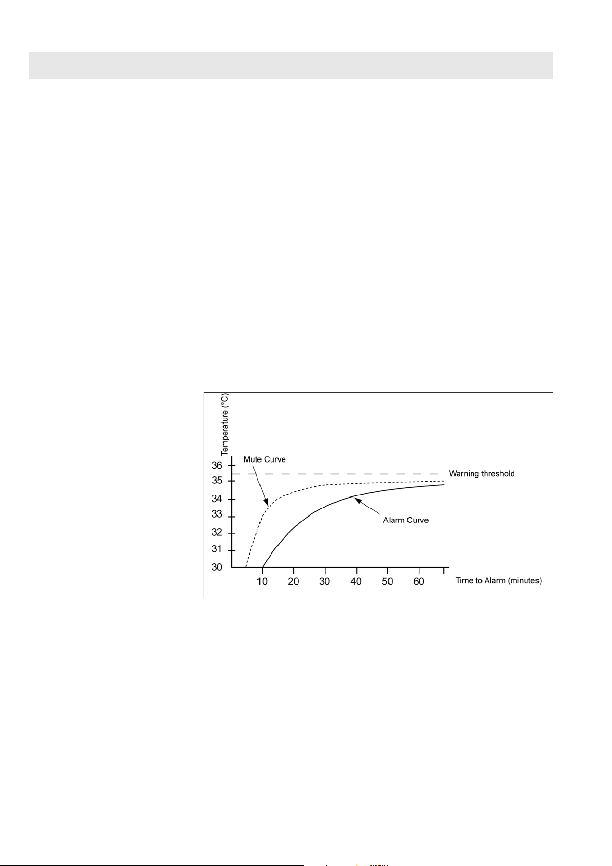
If the humidification chamber temperature is below 35.5 °C for 25 seconds,
the lung symbol will light. If the temperature remains below this level for too
long, then a low humidity alarm is activated.
The time taken for the humidifier to alarm is dependent on how far below the
35.5 °C threshold the temperature is.
The following Figure shows the relationship between temperature and the
time before a warning or alarm is generated:
12
Figure 2 Temperature vs time to alarm
Pressing the mute button silences the audible low humidity alarm for 1 minute
if the same temperature of the humidification chamber temperature probe is
maintained.
The low humidity warning and alarm can occur under the following conditions:
–Cold
– Drafts
– Gas flow rates outside specification of breathing circuit
– Gas flow rates outside specification of humidification chamber
– Gas flow rates outside specification of humidifier.
5697.500
Version 1.2_ Released_Printed on_10.05.06_F5697500T01.fm
For internal use only. Copyright reserved.
Page 17

Annex
Parts catalog
Test List
Page 18

Page 19

Parts catalog
Fisher&Paykel MR 850
Emergency Care - Perioperative Care - Critical Care - Perinatal Care - Home Care
Revision: 2006-03-20 08:50:13
5697.500
Because you care
Because you care
Page 20

2
Page 21
Temp.Sensoradapter
Parts catalog
Item
Part No. Description Qty.
No.
8411044 PROBE-THERMOMETER HOUSING DRAE 1.000 St
Qty.
unit
Remark
5697.500
Items that are shown in the illustration but are not listed below the illustration are not available as spare parts
Revision: 2006-03-20 08:50:13
3
Page 22

Hose heater 1,1m
Parts catalog
Item
Part No. Description Qty.
No.
8411045 HOSE HEATER 1,10 M 1.000 St
Qty.
unit
Remark
5697.500
Items that are shown in the illustration but are not listed below the illustration are not available as spare parts
Revision: 2006-03-20 08:50:13
4
Page 23

Humidifier chamber MR 340(e)
Parts catalog
Item
Part No. Description Qty.
No.
8411047 HUMIDIFIER CHAMBER MR 340 1.000 St
Qty.
unit
Remark
5697.500
Items that are shown in the illustration but are not listed below the illustration are not available as spare parts
Revision: 2006-03-20 08:50:13
5
Page 24

Draw Wire 1,5m
Parts catalog
Item
Part No. Description Qty.
No.
8411050 DRAW WIRE 1,50 M 900 MR 070 1.000 St
Qty.
unit
Remark
5697.500
Items that are shown in the illustration but are not listed below the illustration are not available as spare parts
Revision: 2006-03-20 08:50:13
6
Page 25

Absorbent Paper
A
Parts catalog
Item
Part No. Description Qty.
No.
8411073
BSORBENT PAPER REFILL PACK 1.000 St
Qty.
unit
Remark
Items that are shown in the illustration but are not listed below the illustration are not available as spare parts
5697.500
Revision: 2006-03-20 08:50:13
7
Page 26

Rail Bracket (900MR088)
Parts catalog
Item
Part No. Description Qty.
No.
8411074 MOUNTING KIT F&P 1.000 St
Qty.
unit
Remark
5697.500
Items that are shown in the illustration but are not listed below the illustration are not available as spare parts
Revision: 2006-03-20 08:50:13
8
Page 27

Hose Heater 0,7m
Parts catalog
Item
Part No. Description Qty.
No.
8411154 HEATER WIRE 0,70M HFV-F&P 1.000 St
Qty.
unit
Remark
5697.500
Items that are shown in the illustration but are not listed below the illustration are not available as spare parts
Revision: 2006-03-20 08:50:13
9
Page 28

Humidifier Chamber MR370
Parts catalog
Item
Part No. Description Qty.
No.
8412217 HUMIDIFIER CHAMBER MR 370 (A) 1.000 St
Qty.
unit
Remark
5697.500
Items that are shown in the illustration but are not listed below the illustration are not available as spare parts
Revision: 2006-03-20 08:50:13
10
Page 29

Absorbent Paper Set
A
Parts catalog
Item
Part No. Description Qty.
No.
8412218
BSORBENT PAPER 1.000 St
Qty.
unit
Remark
Items that are shown in the illustration but are not listed below the illustration are not available as spare parts
5697.500
Revision: 2006-03-20 08:50:13
11
Page 30

Y
-Piece F&P
Parts catalog
Item
Part No. Description Qty.
No.
8412220 Y-PIECE F+P 1.000 St
Qty.
unit
Remark
5697.500
Items that are shown in the illustration but are not listed below the illustration are not available as spare parts
Revision: 2006-03-20 08:50:13
12
Page 31

Y
-piece
Parts catalog
Item
Part No. Description Qty.
No.
8412888 Y-PIECE 1.000 St
Qty.
unit
Remark
5697.500
Items that are shown in the illustration but are not listed below the illustration are not available as spare parts
Revision: 2006-03-20 08:50:13
13
Page 32

Temperature probe 1,5m
Parts catalog
Item
Part No. Description Qty.
No.
8414966 Temperature probe 900 MR 869 1.000 St
Qty.
unit
Remark
5697.500
Items that are shown in the illustration but are not listed below the illustration are not available as spare parts
Revision: 2006-03-20 08:50:13
14
Page 33

Adapter Hose heater MR850
A
Parts catalog
Item
Part No. Description Qty.
No.
8414968
dapter hose heater MR850 reus 1.000 St
Qty.
unit
Remark
Items that are shown in the illustration but are not listed below the illustration are not available as spare parts
5697.500
Revision: 2006-03-20 08:50:13
15
Page 34

Hose heater 900MR751
Parts catalog
Item
Part No. Description Qty.
No.
8414969 Hose heater 900 MR 751 1.000 St
Qty.
unit
Remark
5697.500
Items that are shown in the illustration but are not listed below the illustration are not available as spare parts
Revision: 2006-03-20 08:50:13
16
Page 35

Temp./Flow probe 900MR868 1,1m
Parts catalog
Item
Part No. Description Qty.
No.
8414989 Temp./flowsensor 900 MR 868 1.000 St
Qty.
unit
Remark
5697.500
Items that are shown in the illustration but are not listed below the illustration are not available as spare parts
Revision: 2006-03-20 08:50:13
17
Page 36

Hose Set MR850 RT212
Parts catalog
Item
Part No. Description Qty.
No.
8414991 Hose kit for MR 850, RT 212 (10pcs) 1.000 St
Qty.
unit
Remark
5697.500
Items that are shown in the illustration but are not listed below the illustration are not available as spare parts
Revision: 2006-03-20 08:50:13
18
Page 37

Hose Heater Adapter MR801
Parts catalog
Item
Part No. Description Qty.
No.
8414992 Hose heater adapter 900 MR 801 1.000 St
Qty.
unit
Remark
5697.500
Items that are shown in the illustration but are not listed below the illustration are not available as spare parts
Revision: 2006-03-20 08:50:13
19
Page 38

Hose Heater 900MR754
Parts catalog
Item
Part No. Description Qty.
No.
8414993 Hose heater 900 MR 754 1.000 St
Qty.
unit
Remark
5697.500
Items that are shown in the illustration but are not listed below the illustration are not available as spare parts
Revision: 2006-03-20 08:50:13
20
Page 39

Hose SetMR850 RT225
Parts catalog
Item
Part No. Description Qty.
No.
8414994 Hose kit for MR 850, RT 225 (10pcs) 1.000 St
Qty.
unit
Remark
5697.500
Items that are shown in the illustration but are not listed below the illustration are not available as spare parts
Revision: 2006-03-20 08:50:13
21
Page 40

Hose Set E
Parts catalog
Item
Part No. Description Qty.
No.
8414986 Hose kit adult 1.000 St
Qty.
unit
Remark
5697.500
Items that are shown in the illustration but are not listed below the illustration are not available as spare parts
Revision: 2006-03-20 08:50:13
22
Page 41

Hose Set K
Parts catalog
Item
Part No. Description Qty.
No.
8414987 Hose kit paediatric 1.000 St
Qty.
unit
Remark
5697.500
Items that are shown in the illustration but are not listed below the illustration are not available as spare parts
Revision: 2006-03-20 08:50:13
23
Page 42

Adapt. Hoseheater MR850 disp.
A
Parts catalog
Item
Part No. Description Qty.
No.
8414967
dapter hose heater MR850 disp 1.000 St
Qty.
unit
Remark
Items that are shown in the illustration but are not listed below the illustration are not available as spare parts
5697.500
Revision: 2006-03-20 08:50:13
24
Page 43

F&P MR290 Chamber disp.(10pcs)
Parts catalog
Item
Part No. Description Qty.
No.
8418282 F&P MR290 disp.chamber (10p.) 1.000 St
Qty.
unit
Remark
5697.500
Items that are shown in the illustration but are not listed below the illustration are not available as spare parts
Revision: 2006-03-20 08:50:13
25
Page 44

F&F MR290 Chamber (40pcs)
Parts catalog
Item
Part No. Description Qty.
No.
8418283 F&P MR290 Disp.Chamber (40pcs) 1.000 St
Qty.
unit
Remark
5697.500
Items that are shown in the illustration but are not listed below the illustration are not available as spare parts
Revision: 2006-03-20 08:50:13
26
Page 45

F&P MR 340 Chamber (d)
Parts catalog
Item
Part No. Description Qty.
No.
8418286 F&P MR 340 Kammer (d) 1.000 St
Qty.
unit
Remark
5697.500
Items that are shown in the illustration but are not listed below the illustration are not available as spare parts
Revision: 2006-03-20 08:50:13
27
Page 46

F&P Adapter 22f/22m+15f
Parts catalog
Item
Part No. Description Qty.
No.
8418289 F&P adapter 22f/22m+15f 1.000 St
Qty.
unit
Remark
5697.500
Items that are shown in the illustration but are not listed below the illustration are not available as spare parts
Revision: 2006-03-20 08:50:13
28
Page 47

Temp. Probe Adapter D15/D10
Parts catalog
Item
Part No. Description Qty.
No.
8418405 Temperature sensor housing D15/D10 1.000 St
Qty.
unit
Remark
5697.500
Items that are shown in the illustration but are not listed below the illustration are not available as spare parts
Revision: 2006-03-20 08:50:13
29
Page 48

Adapter 900MR533
A
Parts catalog
Item
Part No. Description Qty.
No.
8418407
dapter 900 MR 533 1.000 St
Qty.
unit
Remark
Items that are shown in the illustration but are not listed below the illustration are not available as spare parts
5697.500
Revision: 2006-03-20 08:50:13
30
Page 49

Adapter 900MR830
A
Parts catalog
Item
Part No. Description Qty.
No.
8418455
dapter 900 MR 830 1.000 St
Qty.
unit
Remark
Items that are shown in the illustration but are not listed below the illustration are not available as spare parts
5697.500
Revision: 2006-03-20 08:50:13
31
Page 50

Adapter Hose Heater
Parts catalog
Item
Part No. Description Qty.
No.
MP01001 Heater Wire Adapter (Molex) 1.000 St
Qty.
unit
Remark
5697.500
Items that are shown in the illustration but are not listed below the illustration are not available as spare parts
Revision: 2006-03-20 08:50:13
32
Page 51

U-Shaped mounting bracket
Parts catalog
Item
Part No. Description Qty.
No.
MP01002 Mounting bracket F&P 1.000 St
Qty.
unit
Remark
5697.500
Items that are shown in the illustration but are not listed below the illustration are not available as spare parts
Revision: 2006-03-20 08:50:13
33
Page 52

Humidifier Chamber MR340(F)
Parts catalog
Item
Part No. Description Qty.
No.
8418526 Humidifier chamber MR 340 (fr) 1.000 St
Qty.
unit
Remark
5697.500
Items that are shown in the illustration but are not listed below the illustration are not available as spare parts
Revision: 2006-03-20 08:50:13
34
Page 53

Humidifier Chamber MR340(S)
Parts catalog
Item
Part No. Description Qty.
No.
8418527 Humidifier chamber MR 340 (es) 1.000 St
Qty.
unit
Remark
5697.500
Items that are shown in the illustration but are not listed below the illustration are not available as spare parts
Revision: 2006-03-20 08:50:13
35
Page 54

Basic Unit
Parts catalog
Item
Part No. Description Qty.
No.
Qty.
unit
Remark
5697.500
Items that are shown in the illustration but are not listed below the illustration are not available as spare parts
Revision: 2006-03-20 08:50:13
36
Page 55

Humidifier Basic Unit
Parts catalog
Item
Part No. Description Qty.
No.
1 8418518 Resp. humidifier MR850ALU 1.000 St
1 8418515 Resp. humidifier MR850AEA
1 8418519 Resp. humidifier MR850ANU
1 8418522 Resp. humidifier MR850JHU
1 8418517 Resp. humidifier MR850AFU
1 8418521 Resp. humidifier MR850GJU
1 8418523 Resp. humidifier MR850JSU
1 8418520 Resp. humidifier MR850ARU
1 8418516 Resp. humidifier MR850AEK
1 8418514 Resp. humidifier MR850ADU
1 8414719 Resp. humidifier MR850 AEU
1 8418488 Resp. humidifier MR850AEU (ZH)
1 8414720 Resp. humidifier MR850AGU
1.000 St
1.000
1.000 St
1.000 St
1.000
1.000 St
1.000 St
1.000 St
1.000
1.000 St
1.000 St
1.000
Qty.
unit
St
St
St
St
Remark
5697.500
Items that are shown in the illustration but are not listed below the illustration are not available as spare parts
Revision: 2006-03-20 08:50:13
37
Page 56

Fisher&Paykel MR 850
Assembly Description Part No.
Parts catalog
Absorbent Paper
ABSORBENT PAPER REFILL PACK 8411073
Absorbent Paper Set
ABSORBENT PAPER 8412218
Adapt. Hoseheater MR850 disp.
Adapter hose heater MR850 disp 8414967
Adapter 900MR533
Adapter 900 MR 533 8418407
Adapter 900MR830
Adapter 900 MR 830 8418455
Adapter Hose Heater
Heater Wire Adapter (Molex) MP01001
Adapter Hose heater MR850
Adapter hose heater MR850 reus 8414968
Draw Wire 1,5m
DRAW WIRE 1,50 M 900 MR 070 8411050
F&F MR290 Chamber (40pcs)
F&P MR290 Disp.Chamber (40pcs) 8418283
F&P Adapter 22f/22m+15f
F&P adapter 22f/22m+15f 8418289
F&P MR 340 Chamber (d)
F&P MR 340 Kammer (d) 8418286
F&P MR290 Chamber disp.(10pcs)
F&P MR290 disp.chamber (10p.) 8418282
Hose Heater 0,7m
HEATER WIRE 0,70M HFV-F&P 8411154
Hose heater 1,1m
HOSE HEATER 1,10 M 8411045
Hose heater 900MR751
Hose heater 900 MR 751 8414969
Hose Heater 900MR754
Hose heater 900 MR 754 8414993
5697.500
Revision: 2006-03
38
Page 57

Fisher&Paykel MR 850
Assembly Description Part No.
Parts catalog
Hose Heater Adapter MR801
Hose heater adapter 900 MR 801 8414992
Hose Set E
Hose kit adult 8414986
Hose Set K
Hose kit paediatric 8414987
Hose Set MR850 RT212
Hose kit for MR 850, RT 212 (10pcs) 8414991
Hose SetMR850 RT225
Hose kit for MR 850, RT 225 (10pcs) 8414994
Humidifier Basic Unit
Resp. humidifier MR850 AEU 8414719
Resp. humidifier MR850ADU 8418514
Resp. humidifier MR850AEA 8418515
Resp. humidifier MR850AEK 8418516
Resp. humidifier MR850AEU (ZH) 8418488
Resp. humidifier MR850AFU 8418517
Resp. humidifier MR850AGU 8414720
Resp. humidifier MR850ALU 8418518
Resp. humidifier MR850ANU 8418519
Resp. humidifier MR850ARU 8418520
Resp. humidifier MR850GJU 8418521
Resp. humidifier MR850JHU 8418522
Resp. humidifier MR850JSU 8418523
Humidifier chamber MR 340(e)
HUMIDIFIER CHAMBER MR 340 8411047
Humidifier Chamber MR340(F)
Humidifier chamber MR 340 (fr) 8418526
Humidifier Chamber MR340(S)
Humidifier chamber MR 340 (es) 8418527
Humidifier Chamber MR370
HUMIDIFIER CHAMBER MR 370 (A) 8412217
5697.500
Revision: 2006-03
39
Page 58

Fisher&Paykel MR 850
Assembly Description Part No.
Parts catalog
Products concerned
Resp. humidifier MR850 AEU 8414719
Resp. humidifier MR850ADU 8418514
Resp. humidifier MR850AEA 8418515
Resp. humidifier MR850AEK 8418516
Resp. humidifier MR850AFU 8418517
Resp. humidifier MR850AGU 8414720
Resp. humidifier MR850ALU 8418518
Resp. humidifier MR850ANU 8418519
Resp. humidifier MR850ARU 8418520
Resp. humidifier MR850GJU 8418521
Resp. humidifier MR850JHU 8418522
Rail Bracket (900MR088)
MOUNTING KIT F&P 8411074
Temp. Probe Adapter D15/D10
Temperature sensor housing D15/D10 8418405
Temp./Flow probe 900MR868 1,1m
Temp./flowsensor 900 MR 868 8414989
Temp.Sensoradapter
PROBE-THERMOMETER HOUSING DRAE 8411044
Temperature probe 1,5m
Temperature probe 900 MR 869 8414966
U-Shaped mounting bracket
Mounting bracket F&P MP01002
Y-piece
Y-PIECE 8412888
Y-Piece F&P
Y-PIECE F+P 8412220
5697.500
Revision: 2006-03
40
Page 59

Test List (TL)
Fisher & Paykel MR 850
Notes on field of application:
This test list can be processed with standard commercially available test aids and tools, but
does not replace the inspections and maintenance work carried out by the manufacturer.
Tests marked with the symbol " " are listed in the "Test List Report" and can be
documented there.
Observe protection mark DIN 34. Copyright reserved.
K5697500TL1(Deckblatt).fm 21.03.06
5697.500 Fisher & Paykel MR 850 Released 2001-12-07
Page 60

Contents
1 Unit configuration ......................................................................................................................... 1
1.1 Serial number (SN) ....................................................................................................... 1
2 Maintenance parts ....................................................................................................................... 1
3 Electrical safety ............................................................................................................................ 2
3.1 Electrical safety check as perIEC 60-601 ..................................................................... 2
3.2 Electrical safety check as per VDE 0751 ...................................................................... 3
4 Function and condition test .......................................................................................................... 4
4.1 Power-on test ............................................................................................................... 4
4.2 Heating and control ...................................................................................................... 5
5 Test equipment ............................................................................................................................ 6
5.1 Test equipment subject to calibration ........................................................................... 6
5.2 Test equipment not subject to mandatory calibration ................................................... 6
6 Encs ............................................................................................................................................. 7
I
5697.500 Fisher & Paykel MR 850 Released 2001-12-07
Observe protection mark DIN 34. Copyright reserved.
K5697500TL1IVZ.fm 21.03.06
Page 61

1 Unit configuration
The following equipment and accessories are additionally required for the
following tests on the Fisher & Paykel MR850.
Hose system
Hose adapter
Temperature probes
Ventilator (flow 10 L/min to 30 L/min)
1.1 Serial number (SN)
1.1.1 Fisher & Paykel MR 850 [ __________ ]
1.1.2 Software version [ __________ ]
2 Maintenance parts
- Not applicable -
Observe protection mark DIN 34. Copyright reserved.
K5697500TL1.fm 21.03.06
5697.500 Fisher & Paykel MR 850 Released 2001-12-07
1
Page 62

3 Electrical safety
The following steps describe the electrical safety checks according to
IEC 60-601, see section 3.1, and VDE 0751, see section 3.2. Any
decision about performing safety checks according to VDE 0751 or IEC
60601 must be made under consideration of applicable national
regulations. Electrical safety checks should be carried out either
according to IEC 60-601 or VDE 0751.
3.1 Electrical safety check as perIEC 60-601
3.1.1 Condition test
The Fisher & Paykel MR 850 Respiratory Humidifier and its power cable
are not damaged, dirty, or corroded.
3.1.2 Protective earth conductor test
[OK]
Mains voltage tester
6 V
ohms
L
N
PE
PS
Test specimen
Test probe
Fig.1 Protective earth conductor test
Description of Fig.1:
A test a.c. voltage of approx. 6 V is applied to the protective earth
conductor of the test specimen (Fisher & Paykel MR 850) through a
current limiter. Scan conductive humidification chamber heater plate using
the test probe. The protective earth conductor resistance is calculated
from the flowing current and the voltage present at the test specimen. The
PE current is min. 10 A.
CAUTION
The heater plate has a non-conductive coating. Therefore measure the
protective earth conductor resistance at the bottom edge of the heater
plate.
3.1.2.1 Heater plate [ _____ohms]
The test value should be less than/equal to 0.2 ohms.
2
5697.500 Fisher & Paykel MR 850 Released 2001-12-07
Observe protection mark DIN 34. Copyright reserved.
K5697500TL1.fm 21.03.06
Page 63

3.2 Electrical safety check as per VDE 0751
3.2.1 Condition test
The Fisher & Paykel MR 850 Respiratory Humidifier and its power cable
are not damaged, dirty, or corroded.
3.2.2 Protective earth conductor test
[OK]
Mains voltage tester
6 V
ohms
L
N
PE
PS
Test specimen
Test probe
Fig.2 Protective earth conductor test
Description of Fig.2:
A test a.c. voltage of approx. 6 V is applied to the protective earth
conductor of the test specimen (Fisher & Paykel MR 850) through a
current limiter. Scan conductive humidification chamber heater plate using
the test probe. The protective earth conductor resistance is calculated
from the flowing current and the voltage present at the test specimen. The
PE current is min. 10 A.
CAUTION
The heater plate has a non-conductive coating. Therefore measure the
protective earth conductor resistance at the bottom edge of the heater
plate.
Observe protection mark DIN 34. Copyright reserved.
K5697500TL1.fm 21.03.06
3.2.2.1 Heater plate [ _____ohms]
The test value should be less than/equal to 0.2 ohms.
5697.500 Fisher & Paykel MR 850 Released 2001-12-07
3
Page 64

4 Function and condition test
4.1 Power-on test
Test equipment: Respiratory humidifier MR 850 with hose adapter and
temperature probes.
Fig.3 Power-on test set-up
1. Connect the respiratory humidifier MR 850 to the power supply.
2. Turn on the respiratory humidifier MR 850 using the ON/OFF switch.
The unit completes its self-test. All LEDs and the 7-segment displays
come on briefly. The audible alarm sounds. The device then enters
normal operating mode without any error messages.
3. Turn off the respiratory humidifier MR 850 using the ON/OFF switch.
4. Disconnect the respiratory humidifier MR 850 from the power supply.
[OK]
4
5697.500 Fisher & Paykel MR 850 Released 2001-12-07
Observe protection mark DIN 34. Copyright reserved.
K5697500TL1.fm 21.03.06
Page 65

4.2 Heating and control
Test equipment: Set up Fisher & Paykel MR 850 respiratory humidifier
with breathing circuit, hose adapters, temperature probes, and filled
humidification chamber ready for operation. Ventilator delivering a flow
rate of 10 L/min to 30 L/min, for example Evita.
Fig.4 Heating and control test set-up
1. Connect the Fisher & Paykel MR 850 respiratory humidifier to the
ventilator.
2. Connect ventilator to power supply.
3. Switch on the ventilator.
4. Connect the Fisher & Paykel MR 850 Respiratory Humidifier to the
power supply.
5. Press the power switch on the Fisher & Paykel MR 850 respiratory
humidifier.
The warm-up phase is complete after approx. 30 minutes and
temperatures have stabilized.
6. Press the “alarm silence” key for 1 second.
The chamber temperature is displayed for approx. 2 seconds, and the
chamber LED comes on. Then the airway temperature is displayed for
approx. 2 seconds, and the airway temperature LED comes on.
The humidification chamber temperature is in the range 35.2 °C to
37.3 °C.
[OK]
The patient temperature is in the range 38.2 °C to 40.3 °C.
No alarms occur.
7. Switch off the ventilator.
8. Disconnect the ventilator from power supply.
9. Turn off the Fisher & Paykel MR 850 respiratory humidifier using the
ON/OFF switch.
10.Disconnect the Fisher & Paykel MR 850 Respiratory Humidifier from
the power supply.
Observe protection mark DIN 34. Copyright reserved.
K5697500TL1.fm 21.03.06
5697.500 Fisher & Paykel MR 850 Released 2001-12-07
5
Page 66

5 Test equipment
5.1 Test equipment subject to calibration
Subject to
Designation Characteristics/Info
calibration
Mains voltage tester 1.6
5.2 Test equipment not subject to mandatory calibration
Designation Characteristics/Info Class
Ventilator Flow 10 to 30 L/min 1.6
Water container 2 L volume
Thermometer +0.5 °C/-0.5 °C
6
5697.500 Fisher & Paykel MR 850 Released 2001-12-07
Observe protection mark DIN 34. Copyright reserved.
K5697500TL1.fm 21.03.06
Page 67

6Encs
- Not applicable -
Observe protection mark DIN 34. Copyright reserved.
K5697500TL1.fm 21.03.06
5697.500 Fisher & Paykel MR 850 Released 2001-12-07
7
Page 68

Test List Report Fisher & Paykel MR 850
Test List Edition: 2001-12-07
Installation site: __________
OK Result
( ) 1.1 Serial number (SN)
( ) 1.1.1 Fisher & Paykel MR850 [ __________ ]
( ) 1.1.2 Software version [ __________ ]
( ) 3.1 Electrical safety check as perIEC 60-601
( ) 3.1.1 Condition test
( ) 3.1.2 Protective earth conductor test
( ) 3.1.2.1 Heater plate [ _____ohms]
( ) 3.2 Electrical safety check as per VDE 0751
( ) 3.2.1 Condition test
( ) 3.2.2 Protective earth conductor test
( ) 3.2.2.1 Heater plate [ _____ohms]
4 Function and condition test
( ) 4.1 Power-on test
( ) 4.2 Heating and control
OK Result
Supply tested and fully functional device to owner/user.
Date: Name/Signature: 8
Observe protection mark DIN 34. Copyright reserved.
K5697500TL1EAL.fm 21.03.06
Page 69

Page 70

Manufacturer: Support:
Fisher & Paykel Healthcare Limited Dräger Medical AG & Co. KG
15 Maurice Paykel Place, East Tamaki Moislinger Allee 53 – 55
PO Box 14 348 Panmure Auckland 6 D-23542 Lübeck
New Zealand Germany
Phone: (+64) 9 574 0100 Phone: (+49) (0) 1805-3723437
Fax: (+64) 49 574 0158 Fax: (+49) 451/882 - 3779
Subject to change without notice
Will not be replaced in the event of modifications.
© Copyright by Dräger Medical AG & Co. KG, Lübeck, Germany.
The warranty and liability conditions of the general terms and conditions for business transactions of
Dräger Medical AG & Co. KG are not extended by this Technical Documentation.
 Loading...