

Fisher Mechanical Setting of Disk/Stem Taper Pins Installation Instructions Manuals & Guides
Page 1

Installation Instructions
D103982X012
Mechanical Setting of Disk/Stem Taper Pins
Mechanical Setting of Disk/Stem Taper Pins
Purpose
September 2019
The purpose of this document is to provide instructions on how to mechanically set the taper pins used in some
disk/stem assemblies, including but not limited to: Fisher
valves. Note these instructions do not apply to constructions that use straight pins (or grooved straight pins).
™
7600, 7700, 7800, 9100, 9200, and 9500 series butterfly
Inspection
If either the disk or shaft is being reused, it is recommended that they are inspected for defects to ensure they will
perform as desired.
If the shaft is not in likenew condition, it is a candidate for repair or replacement.
D The shaft surface that mates with packing should be absolutely straight, smooth, and free of nicks, scratches, or
pitting. Check for straightness by placing the shaft in a lathe, in Vblocks, or on a granite table. Make sure the splines
are straight by looking down the end of the shaft. Examine the bearing contact surfaces for any signs of wear or
galling. Also make sure that the holes the taper pins go through are not worn or egg-shaped.
Note
If taper pin holes have been widened by loosening of taper pins or otherwise damaged, install a new disk/shaft assembly.
D Also inspect the edge of the disk to ensure it is in fairly good condition (depending on the valve’s intended shutoff
rating). If the disk is bent, eroded, or corroded, consider replacement.
Installation
1. Install the disk and shaft into the valve body.
2. Insert the pins into the larger end of the pin holes. Without driving the pins in with a hammer, mark the match-line
between the pins and the disk on the surface of the pins.
3. Remove the pins and grind the top of the pins down to the marked match-line.
4. Reinsert the pins into the larger end of the pin holes. Drive with a hammer to seat the pins. Drive with a hammer to
seat the pins. The surface of the pin should be approximately 1/8” below the surface of the disk. Additionally, the
smaller end of the pins should extend past the surface of the disk on the smaller end of the pin holes.
5. To stake the pins, deform the metal at the outer perimeter of the pinholes in three locations to secure the pins
inside the disk. Ensure that disk material has been deposited over the pins in order to prevent them from slipping
out. Additionally, ensure that the disk material is deformed deep enough to contact the top surface of the pins.
6. For elastomer-lined valves, consult the appropriate product literature for instructions on coating the taper pin with
sealant. The pins should be coated with a thin, uniform film of sealant prior to installation.
www.Fisher.com
Page 2
Installation Instructions
Mechanical Setting of Disk/Stem Taper Pins
D103982X012
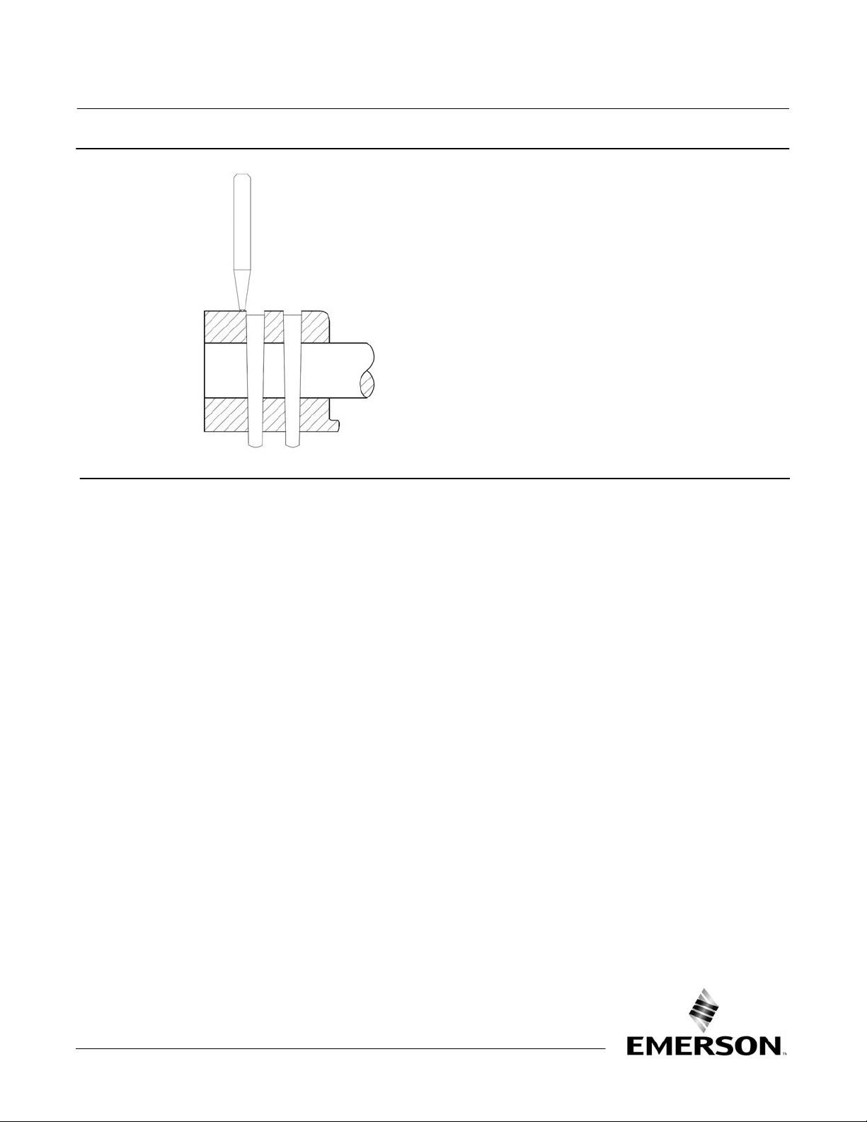
Figure 1. Mechanical Setting of Disk/Stem Taper Pins
NOTE:
STAKE THE PINS BY DEFORMING DISK MATERIAL IN THREE LOCATIONS FROM THE CIRCUMFERENCE OF EACH PINHOLE OVER THE PINS.
September 2019
Neither Emerson, Emerson Automation Solutions, nor any of their affiliated entities assumes responsibility for the selection, use or maintenance
of any product. Responsibility for proper selection, use, and maintenance of any product remains solely with the purchaser and end user.
Fisher is a mark owned by one of the companies in the Emerson Automation Solutions business unit of Emerson Electric Co. Emerson Automation Solutions,
Emerson, and the Emerson logo are trademarks and service marks of Emerson Electric Co. All other marks are the property of their respective owners.
The contents of this publication are presented for informational purposes only, and while every effort has been made to ensure their accuracy, they are not
to be construed as warranties or guarantees, express or implied, regarding the products or services described herein or their use or applicability. All sales are
governed by our terms and conditions, which are available upon request. We reserve the right to modify or improve the designs or specifications of such
products at any time without notice.
Emerson Automation Solutions
Marshalltown, Iowa 50158 USA
Sorocaba, 18087 Brazil
Cernay, 68700 France
Dubai, United Arab Emirates
Singapore 128461 Singapore
www.Fisher.com
2
E 2014, 2019 Fisher Controls International LLC. All rights reserved.
 Loading...